© 2017, IRJET | Impact Factor value: 5.181 | ISO 9001:2008 Certified Journal | Page 2340
Harmonic Mitigation using Modified Synchronous Reference
Frame Theory
Mr. Bhushan S. Rakhonde
1, Astt.Prof. C. M. Bobade
21
M.E. student, Electrical Power System Engineering, G.H.R.C.E.M. Amravati, Maharashtra, India
2
Assistant Professor, Electrical Engineering Department, G.H.R.C.E.M. Amravati, Maharashtra, India
---***---Abstract -
Use of nonlinear load increasing day by daybecause it consumes less power as compared to linear load. Although this power electronics equipment make our life convenient, they inject harmonic into power system. These harmonics affects amplitude and nature of source current and hence performance of system. Therefore power quality became very serious issue. Conventionally, passive filters have been used to eliminate harmonics from power system but it has some limitations. So, new solution to eliminate harmonics is developed which is shunt active power filter.
This paper presents a new three-phase shunt active power filter to compensate harmonics is implemented in MATLAB. Main part of shunt active power filter is reference current generation control algorithm. This Paper includes simulation of three reference current generation techniques viz. Modified synchronous reference frame (MSRF) theory,
Key Words: Instantaneous Reactive Power Theory, Total Harmonic Distortion (THD), Reference current generation, filter, power quality, Shunt Active Power Filter.
1.INTRODUCTION
As we know that the harmonics generated by nonlinear loads affects on amplitude and nature of source current hence the performance of system. Nonlinear loads cause high disturbances on power system. harmonics cause many problems like heat, losses, failure of electrical equipment and interference with communication system. So, elimination of harmonics is important issue and to solve this problem shunt active power filter (SAPF) came into action[1].
The most popular solution to eliminate these harmonics is Shunt Active Power Filter (SAPF) because SAPF can eliminate harmonics easily, overcome voltage sag and improves power factor[6].
Significance of SAPF can be understood as follows. Assume that load connected to system is drawing unbalanced harmonic current. In addition, the load power factor is poor. This will obviously lead to unbalance and distortion in other system quantities which is undesirable.
Therefore, it important to install some corrective measures in system to solve above problem. It is well known that shunt capacitor is good solution for correcting poor power factor. Similarly tuned filter are also used with power electronic loads to bypass harmonic currents. The problem of load balancing also has to solve by some method. However, all these problems can be solved by single device which is called shunt active power factor (SAPF). Principle of SAPF is to inject current in the system which is equal and opposite in polarity to harmonic current. It has many advantages over passive filter like reactive power compensation, voltage regulation also SAPF is smaller, more versatile, more selective, better damped and less prone to failure. They are studied widely and great developments have taken place in theory and application of active power filters. The performance of SAPF depends on control algorithm used for reference current generation which is then used as a reference for filter current. Finally, this filter current is used for compensation of harmonics. In this way, we can achieve harmonic mitigation and improve power quality, voltage regulation, load current unbalance, power factor etc. of power system.
When shunt active power filter is connected in the system and modified synchronous reference frame method is used for reference current generation then the percentage THD is reduced to 3.25%.
1.1
Passive Filter
Passive filters have been most commonly used to limit the flow of harmonics currents in distribution system. They are usually custom designed for application. However, their performance is limited to a few harmonics and they can introduce resonance in the power system.
© 2017, IRJET | Impact Factor value: 5.181 | ISO 9001:2008 Certified Journal | Page 2341 and cost. These filters are tuned and fixed according to the
impedance of the point at which they will be connected and hence cannot be adjusted instantaneously in accordance to the load. As a result their cutoff frequency changes unexpectedly after any change in the load impedance resulting in producing a resonance with other elements installed in the system. Other drawbacks are interference with communication system, they are heavy and bulky, overloaded when the load harmonics increase.
1.2 Active Filter
There are basically two types of active filters: the shunt type and the series type. Shunt active power filter is able to compensate for both current harmonics and power factor. Furthermore, it allows load balancing, eliminating the current in the neutral wire. Series active power filter is the dual of the shunt active filter, and is able to compensate for distortion in the power line voltages, making the voltages applied to the load sinusoidal (compensating for voltage harmonics). Depending on the particular application or electrical problem to be solved, active power filters can be implemented as shunt type, series type, or a combination of shunt and series active filters (shunt-series type). These filters can also be combined with passive filters to create hybrid power filters.
The shunt-connected active power filter, with a self-controlled dc bus, has a topology similar to that of a static compensator (STATCOM) used for reactive power compensation in power transmission systems. Shunt active power filters compensate load current harmonics by injecting equal-but opposite harmonic compensating current. In this case the shunt active power filter operates as a current source injecting the harmonic components generated by the load but phase-shifted by 180°. Series active power filters were introduced by the end of the 1980s and operate mainly as a voltage regulator and as a harmonic isolator between the nonlinear load and the utility system. The series-connected filter protects the consumer from an inadequate supply voltage quality.
2. BASIC COMPENSATION PRINCIPLE
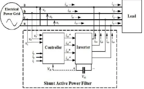
The basic principle of a shunt active power filter is that it generates a current equal and opposite in polarity to the harmonic current drawn by the load and injects it to the point of common coupling, thereby forcing the source current to be pure sinusoidal. Harmonic and reactive currents are thus cancelled at the source end and the result is undistorted sinusoidal balanced currents.
Fig.1 shows the basic compensation principle of shunt active power filter. It is controlled to supply a compensating current ic into the system, so that it cancels
current harmonics on the AC side, and makes the source current in phase with source voltage as explained in above
principle. Fig.2 shows different waveforms. Curve A is the load current waveform and curve B is the desired mains current. Curve C shows the compensating current injected by the active filter containing all the harmonics, to make mains current sinusoidal.
[image:2.595.318.555.270.416.2]In this way, by eliminating harmonics from power system shunt active power filter plays an important role in power quality improvement. It also helps in reactive power compensation, voltage regulation etc. Shunt active power filter is smaller, more versatile, more selective, better damped and less prone to failure as explained in first chapter. Due to these advantages SAPF is most widely used solution for power quality problem.
[image:2.595.320.551.465.566.2]Fig -1: Block diagram of Shunt Active Power Filter
Fig -1: Shunt active power filter-Shapes of load, source and desired filter current waveforms
3.
THEORIES FOR REFERENCE CURRENT
GENERATION
© 2017, IRJET | Impact Factor value: 5.181 | ISO 9001:2008 Certified Journal | Page 2342
3.2 Modified Synchronous Reference Frame (MSRF)
Theory
The modified synchronous reference frame method is also called as the instantaneous current component ( ) method. As the name suggest this method is similar to the SRF method only small modification is done. In SRF method we get transformation angle from PLL, but here in modified SRF, transformation angle is obtained with the voltages of AC network. Similar to SRF method it is also based on the principle that harmonics change their frequency in a rotating reference frame, so they are better isolated with filters.
The difference is that due to voltage harmonics and imbalance, the speed of reference frame is no longer constant. It varies instantaneously depending on the waveform of the three phase voltage system. One of the important characteristics of this algorithm is that compensating currents are obtained from the instantaneous active and reactive current components of the nonlinear load. This method can achieve fast and accurate extraction of the harmonic content and of the reactive component of a distorted current.
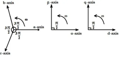
[image:3.595.37.291.540.661.2]Reference frame transformation is the transformation of coordinates from a three-phase a-b-c stationary coordinate system to the 0-d-q rotating coordinate system. Therefore similar to synchronous reference frame method, here first we convert three phase a-b-c stationary coordinate system to two-phase α-β stationary coordinate system which is called Clark’s transformation. Then this two phase α-β stationary coordinate system is converted into two phase d-q rotating coordinate system which is called Park’s transformation.
Fig 3.2: Reference Frame Transformation
The source current and source voltage are first detected, and then in first step
Clark’s transformation is done.
If, source currents are , , and source voltages are , , then they are transformed to two phase stationary reference frame as shown by equation below.
=
and
=
Now, the two phase current quantities and of stationary αβ-axes are transformed into two-phase synchronous rotating reference frame ( and ) i.e. Parks transformation. Here, this transformation is done as follows:
=
Instantaneous active and reactive load currents can be decomposed into oscillatory and average terms. The fundamental currents of the d-q components are now dc values and harmonics appear like ripple. Harmonic isolation of the d-q transformed signal is required for reference current. This is accomplished using LPF with an appropriate cut-off frequency and damping constant. This gives us reference current in d-q form which is harmonic free.
=
Where,
– Mean value of instantaneous real current. It is the only desired current component to be supplied by the power source.
– Alternating value of the instantaneous real current. Since it does not involve any energy transfer from the power source to load, it must be compensated.
– Mean value of instantaneous imaginary current.
– Alternating value of the instantaneous imaginary current.
The reference current signal in d-q rotating frame is converted back into a-b-c stationary reference frame. The reverse transformation from d-q rotating frame is achieved with two steps d-q to α-β and again α-β to a-b-c.
© 2017, IRJET | Impact Factor value: 5.181 | ISO 9001:2008 Certified Journal | Page 2343 =
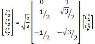
In second step, two phase α-β stationary reference frame is converted to three phase a-b-c stationary reference frame and it is called as inverse Clark’s transformation. It is given by,
=
These are the three phase stationary reference current a-b-c which are harmonic free. These reference currents are used for the generation of the PWM pulses by using the hysteresis current controller (HCC).
In the hysteresis current controller we compare reference current with the load current and filter current to get the pulses for the inverter.
By using
=
-
=
-
= -
These pulses will be used for triggering of the IGBT’s used in the inverter circuit. With these GATE pulses the output of inverter is the filter current i.e. the compensating current required to eliminate the harmonics, these filter current is fed to the system to compensate the harmonics in the system.
3.3 Block Diagram of Modified SRF Method
Fig. 3.3 shows the basic block diagram of modified SRF method for reference current generation. The current of phase a-b-c is detected first and converted to α-β using Clark’s transformation. Then this current in α-β form is converted to d-q form using Park’s transformation. Here, for Park’s transformation and is used. Then LPF removes the harmonics from current which gives reference current in d-q form. Finally, reference current in a-b-c is calculated by using inverse Clark’s and inverse Park’s transform.
3.4 Advantages and Disadvantages of MSRF theory
Advantages of MSRF Theory:
This method is best suitable for harmonic compensation with sinusoidal source voltage. Easily implementable and robust
Disadvantages of MSRF theory:
Large numbers of voltage and current transducers are required.
Fig 3.3: Block Diagram of MSRF method
4.
REFERENCE CURRENT GENERATION BY
MODIFIED SYNCHRONOUS REFERENCE METHOD
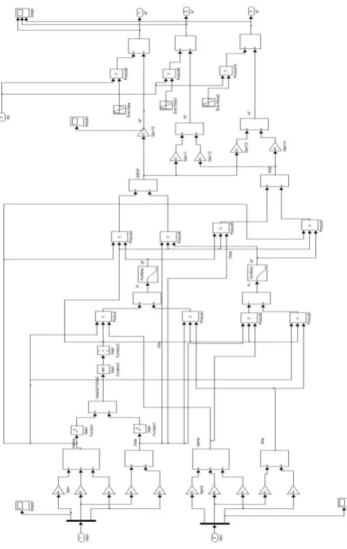
[image:4.595.100.259.187.260.2]The basic block diagram of this method is shown in figure 3.3. The MATLAB simulation block diagram for this method is as shown in fig.4 below. Similar to SRF method it is also based on the principle that harmonics change their frequency in a rotating reference frame, so they are better isolated with filters. Simulation diagram clearly shows that transformation angle is obtained with the voltages of AC network instead of phase locked loop.
First we convert three phase a-b-c stationary coordinate system to two-phase α-β stationary coordinate system (Clark’s Transformation) then this two phase α-β stationary coordinate system is converted into two phase d-q rotating coordinate system (Park’s Transformation). In two phase rotating coordinate system, current can be easily differentiate into oscillatory i.e. harmonic component and average fundamental component. Now, Harmonic isolation of the d-q transformed signal is done using LPF with an appropriate cut-off frequency. This gives us reference current in d-q form which is harmonic free. The reference current signal in d-q rotating frame is converted back into a-b-c stationary reference frame. The reverse transformation from d-q rotating frame is achieved with two steps d-q to α-β (Inverse Park’s Transformation) and again α-β to a-b-c (Inverse Clark’s Transformation).
© 2017, IRJET | Impact Factor value: 5.181 | ISO 9001:2008 Certified Journal | Page 2344 current. Accordingly switching signals are generated for
[image:5.595.293.556.135.695.2]inverter.
Fig 4: MATLAB Simulation diagram of MSRF method
5. SIMULATION RESULTS AND ANALYSIS
5.1 Performance of shunt active power filter with
Modified SRF theory
Fig. 5.1 below shows the waveform when SAPF is connected in system and modified SRF theory is used for reference current generation. Fig. (i) of 5.1 shows the reference current which obtained by using modified SRF theory. Second waveform shows filter current which is equal and opposite of the harmonic current. Third waveform shows load current and forth waveform shows three phase source current. It is clearly seen that when SAPF is connected then source current is sinusoidal.
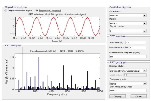
Fig. 5.2 shows FFT analysis of source current waveform when SAPF is connected and MSRF is used for
reference current generation. The THD in source current is reduced to 3.25% after compensation.
(i) Reference Current
(ii) Filter Current
(iii) Harmonic Current
(iv)
(v)
(vi)
(iv) Source Current [image:5.595.45.293.138.530.2]© 2017, IRJET | Impact Factor value: 5.181 | ISO 9001:2008 Certified Journal | Page 2345 Fig. 5.2: FFT analysis of source current with MSRF theory
REFERENCES
[1] Bhim Singh, J. Solanki, “A Comparison of Control
Algorithms for DSTATCOM”, IEEE Transactions on Industrial Electronics, VOL. 56, NO. 7, Page(s): 2738 – 2745, JULY 2009.
[2] A. Bhattacharya, C. Chakraborty and S. Bhattacharya,
“Shunt Compensation, Reviewing Traditional Methods of Reference Current Generation”, IEEE Industrial Electronics Magazine, Sept. 2009.
[3] Akagi H., Kanazawa Y., Nabae A., “Instantaneous reactive
power compensation comprising switching devices without energy storage components”, IEEE Trans. Ind. Appl., vol. IA-20, 2010, pp- 625-630.
[4] Chen Duo, Chen Xincan, Kang Mingcai, “An Analysis on
Sequence of the Harmonic in Power System”, China International Conference on Electricity Distribution (CICED 2014).
[5] P. Santiprapan and K-L. Areerak, “Performance
Improvement of Harmonic Detection using Synchronous Reference Frame Method”, International Conference on Advances in Energy Engineering 2010.
[6] Nilesh M. Chamat, Prof. S. P. Diwan, Vikas S. Bhandare
and Snehal Jamadade, “Instantaneous Reactive Power Theory for Real Time Control of Three-Phase Shunt Active Power Filter (SAPF),” 2014 International Conference on Circuit, Power and Computing Technologies [ICCPCT], IEEE, pp. 792- 796.
[7] P. Salmerón and S. P. Litrán, “Improvement of the
Electric Power Quality Using Series Active and Shunt Passive Filters”, IEEE Transactions on Power Delivery, Vol. 25, April 2010, pp. 1058-1067.
[8] SQUARE D Product Data Bulletin, Power System
Harmonics Causes and Effects of Variable Frequency
Drives Relative to the IEEE 519-1992 Standard, Bulletin No. 8803PD9402, August, 1994.
BIOGRAPHIES
Mr. Bhushan S. Rakhonde He received Bachelor of Engineering degree in Electrical Engineering. pursuing Master of Engineering in Electrical Power System Engineering, G.H.R.C.E.M. Amravati, Maharashtra, India
Mr. C. M. Bobade