REDUCTION OF SO URCE CURRENT HARMONICS IN AN INVERTER FED
INDUCTION MOTOR WITH AN INPUT ACTIVE FILTER ALONG WITH PI
CONTROLLER
M Padmarasan
1, Balaji.R
2, Harinath M K
3, Jagan Kishore
41Associate professor, Dept. of EEE, Panimalar Institute of Technology, Chennai 2,3,4UG Scholar, Dept. of EEE, Panimalar Institute of Technology, Chennai
---***---Abstract: The motor drive systems are generally equippedwith rectifiers and inverters which are composed of power switches and reactive components. This appliance produces harmonics and reactive power. This harmonic current level tends to increase, as the power of the appliances increases.In this project, an active filter system along with a PI controller which is capable of filtering the harmonic current produced by the induction motor is proposed.
Keywords; Motor drives, harmonics, shunt active filter, pi controller
1 INTRODUCTION
Harmonics have existed from the earliest days of the industry and were (and still are) caused by the non-linear magnetizing impedances of transformers, reactors, fluorescent lamp ballasts, induction motors etc. In addition, power electronic devices have become abundant today because of their capabilities for precise process control and energy savings benefits.
Harmonic currents caused by nonlinear loads connected to the distribution system are flowing through the system impedances, and in turn distorts the supply voltage. Such loads are increasingly more abundant in all industrial, commercial, and residential installations and their percentage of the total load is growing steadily. Harmonic currents increase the r.m.s. current in electrical systems and deteriorate the supply voltage quality. They stress the electrical network and potentially damage equipment. They may disrupt normal operation of devices and increase the operating costs.
In passive filters, circuit becomes bulky if inductors are used. These circuits cannot provide any gain and there is always some loss of signal. Hence we go for active filters. Active filters are small in size and less bulky. It is inexpensive compared to that of passive filters due to the variety of cheaper op-amp and the absence of costly inductors.
2. PROPOSED TOPOLOGY
Three phase shunt active filter is used as a prototype as shown in figure. The shunt active power filter(SAPF) is used to produce mitigation current in opposite phase. Power circuit for SAPF is planned as a MOSFET based three-phase voltage source inverter with DC storage
capacitor for better mitigation of non-sinusoidal unbalanced/balanced loads. The active power filter has a control scheme i.e PI controller for DC voltage regulation. The capacitors are planning to limit the DC voltage ripple to a particular value, typically 1 to 2%. In this case the capacitor should be planned for the worst case. Since the shunt active filter will operate in several modes(balanced or unbalanced), then the injection of mitigation current is complete in order to nullify or compensate the harmonic currents. Injection of this mitigation current gives enhanced power quality. The performance of the shunt active power filter is dependent to a great extent upon the method used for the estimate of reference current.
2.1 HUNT ACTIVE POWER FILTER
In the present electrical distribution system, there has been a rapid increase of distorted loads such as power supplies, domestic appliances, rectifier gear and adjustable speed drives(ASD), etc. As the number of these loads rises, harmonic currents generated by these loads may become very significant. These harmonics could lead to a variety of different power system issues including the distorted voltage waveforms, gear overheating, malfunction in system protection, incorrect power flow metering, excessive neutral currents, light flicker etc. They have also decreased efficiency by drawing reactive current component of the distribution network.
In order to overcome these issues active power filters (APFs) has been developed. The voltage source inverter (VSI) based shunt active filter has been used in present and is known as a viable solution. The active filter is a flexible and dynamic solution for the mitigation of harmonic currents due to their compact size, no requirement of tuning and static operation. The active filters are categorized into two types based on topology: current source active filters (CSAF) and voltage source active filters (VSAF). Inductor is used to store DC energy in current source active filter and capacitor is used as an energy storage device in voltage source active filter. The VSAFs are preferred because it has less cost, smaller size and easier to control compared to CSAFs.
2.2 BASIC DIAGRAM
Fig.2.1.Shunt active power filter with non-linear load
2.3 CONTROL TECHNIQUES
The switching pulses of an active filter circuit are generated using two common techniques such as direct current control(current reference) and indirect current control(voltage reference). The direct current control technique is preferred to the shunt active power filter over indirect current control due to fast response and robustness. The direct current control technique is adapted to generate the switching gate pulses along with any one of the controls like hysteresis control and ramp comparison control etc.
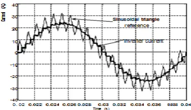
2.4RAMP COMPARISON METHOD
In this mode of controller, sine wave reference signal produced is added with a triangular signal to create other sinusoidal triangular reference. This reference is then compared with actual current. The point where sinusoidal triangular wave and actual current cross becomes time when inverter leg is switched. This method causes inverter switching frequency and PWM pulses wide vary and give different current ripples in one inverter period. Ramp comparison method tends to give lower distortion due to increase of load current. This method is better in form of lower effect on line current distortion.
Fig.2.4.Current shape for ramp comparison method
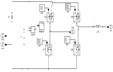
3. PROPOSED SYSTEM:
[image:2.595.333.533.133.272.2]INVERTER FED INDUCTION MOTOR WITH FRONT END ACTIVE FILTER SYSTEM AND PI CONTROLLER
Fig 3.1. Block diagram of proposed system
The above fig is the block diagram of linear and non linear load in which the total harmonic distortion value is to be reduced using an input active filter and PI controller at the source end. It includes 2 level 4 pulse PWM current generator to generate the pulses from the PI controller.
3.1 INDUCTION MOTOR WITHOUT ACTIVE FILTER AND PI CONTROLLER
Fig 4.2 Simulink diagram of linear load without active filter and PI controller. The above fig is the simulink diagram of
an inverter fed induction motor without an active filter and PI controller.
[image:2.595.321.557.415.579.2] [image:2.595.65.253.632.740.2]3.2 INDUCTION MOTOR WITH ACTIVE FILTER AND PI CONTROLLER
Fig.4.3. Simulink diagram of linear load with active filter and PI controller
The above fig is the simulink diagram of an inverter fed induction motor with an active filter and PI controller. The current is taken as a feedback from the induction motor and compared with reference current, whose error signal is given to the PI controller.
[image:3.595.333.540.119.293.2]3.3 LINEAR AND NON LINEAR LOAD WITHOUT ACTIVE FILTER AND PI CONTROLLER
Fig.4.4. Simulink diagram of linear and non linear load without active filter and PI controller
The above fig is the simulink diagram of a linear(induction motor) and non linear load(diode fed resistive load) without an active filter and PI controller.In this circuit the total harmonic distortion value is measured for the combination of linear and non linear load at the source side.
[image:3.595.70.268.415.666.2]3.4 LINEAR AND NON LINEAR LOAD WITH ACTIVE FILTER AND PI CONTROLLER
Fig. 4.5.Simulink diagram of linear and non linear load with active filter and PI controller
The above fig is the simulink diagram of linear load (induction motor) and non linear load(diode fed resistive load) with an active filter and PI controller. The signal from the PI controller is given to the 2 level 4 pulse PWM generator. These pulses are given to the gate terminal of the MOSFET which is used in the rectifier circuit.
3.5 INVERTER CIRCUIT
It comprises of six MOSFET devices which is triggered by the pulses from the Space Vector Modulation block. It converts the ripple free DC voltage into 3 phase AC voltage which is fed to the induction motor.
3.6 RECTIFIER CIRCUIT
It comprises of 4 power diodes connected across a resistor. It converts the AC voltage from the source into DC which is sent to the DC link to remove the ripple content.
3.7 ACTIVE FILTER CIRCUIT DIAGRAM
Fig. 4.8 Simulink diagram of active filter circuit
[image:3.595.336.530.604.728.2]It is similar to a rectifier circuit which comprises of four MOSFET devices triggered using gate pulses.
It converts the DC voltage into AC which is injected into the system near the source.
EQUATIONS
The differential equations related to shunt active filter and PI controller are
t
I
i
t
V
v
m s m s
sin
sin
F C C s F Fi
m
dt
dV
C
mV
v
i
R
dt
di
L
From equations (4) and (5),
dt
dv
C
i
m
dt
di
L
i
R
v
v
m
c F F F s cs *1
1
iF kp(vcVC)ki
(vc VC)dt where,iF – filter current,
iF* – reference filter current
is – source current
is* – reference source current
iL – load current
VC – measured dc link capacitor voltage
vC – reference dc link capacitor voltage
m - Constant
In this proposed system, space vector control pulse width modulation (SVPWM) technique is adopted for inverter fed squirrel cage induction motor (SCIM) drive system to achieve the better performance and reduction of harmonic effects.
4 SIMULATION RESULTS
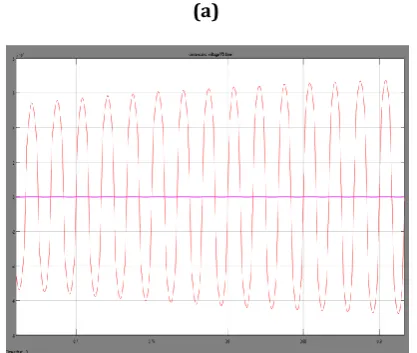
4.1 OUTPUT WAVEFORM AND THD VALUE FOR LINEAR LOAD WITHOUT ACTIVE FILTER AND PI CONTROLLER
(a)
(b)
Fig.4.11. (a) Waveform (b) FFT analysis diagram in which the total harmonic distortion value is found to be 189.46%
[image:4.595.330.539.583.759.2](b)
Fig.4.12. (a) Waveform (b) FFT analysis diagram in which the total harmonic distortion value is found to reduced to
14.04%
4.3 OUTPUT WAVEFORMS AND THD VALUE OF LINEAR AND NON LINEAR LOAD WITHOUT ACTIVE FILTER AND PI CONTROLLER
(a)
(b)
Fig.4.13. (a) Waveform (b) FFT analysis diagram in which the total harmonic distortion value is found to be 69.07%
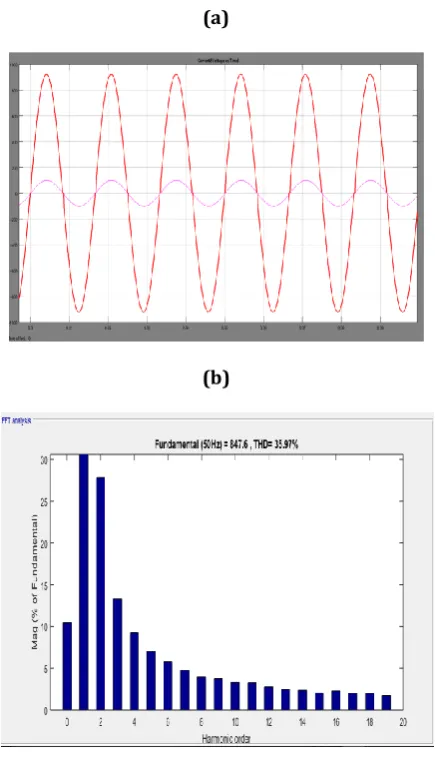
4.4 OUTPUT WAVEFORMS AND THD VALUE OF LINEAR AND NON LINEAR LOAD WITH ACTIVE FILTER AND PI CONTROLLER
(a)
(b)
Fig.4.14. (a) Waveform (b) FFT analysis diagram in which the total harmonic distortion value is found to be reduced
to 35.97%
5 CONCLUSION
The solid state AC-AC converter system with diode fed R load and induction motor loads are modelled and simulated successfully.The results of simulation with and without active filter in supply side are presented. The simulation results indicate that the harmonics are reduced by about 92.58% by introducing active filter and PI controller in the supply side for only linear load and reduced by about 60.85% by introducing active filter and PI controller for both linear and non linear load. The advantages of this system are that the line drop and line losses are reduced by introducing active filter.
[image:5.595.58.268.84.278.2] [image:5.595.325.543.120.500.2] [image:5.595.61.266.402.749.2]The reduction of current harmonics using two inductor power factor correction circuits will be done in future.
6. COMPARISON TABLE
The above table is the comparison results for the various loads used in the simulation diagrams.
For the induction motor load, with the use of active filter and PI controller, the total harmonic distortion value has been reduced to about 92.58% and for the non linear load ie, diode fed resistive load, with the use of active filter and PI controller , the total harmonic distortion value has been reduced to about 60.85% which is enough to increase the efficiency of the motor system to a great extent.
REFERENCES:
1. Roger C.Dugan, Mark F. McGranaghan, Surya Santoso and H.Wayne Beaty, ―Electrical power system quality, Mcgraw-Hill.
2. H. Akagi, ―Trends in active power line conditioners, IEEE Trans. Power Electronics, vol. 9, no. 3, pp. 263 May 1994.
3.K. Sangsun, and P. N. Enjeti, "A new hybrid active power filter (APF) topology", IEEE Transactions on Power Electronics, vol.17, no. 1, pp. 48
4. H. Akagi, Y. Kanazawa, and A. Nabae, ―Instantaneous reactive power compensators comprising switching devices without energy storage components, IEEE Transaction Industrial Applications, vol. IA-20, pp. 625-630, May/June 1984.
5. F. Z. Peng, H. Akagi, and A. Nabae, ―A study of active power filters using quad series voltage source pwm converters for harmonic compensation, IEEE Transactions on Power Electronics, vol. 5, no. 1,pp. 9–15, January 1990.
6. Conor A. Quinn, Ned Mohan, ―Active Filtering of Harmonic Currents in Three-phase, Four-Wire Systems with Three-phase and Single-phase Non-Linear Loads, IEEE-1992.
LOADS
WITHOUT PI CONTROLLER
AND ACTIVE FILTER
WITH PI CONTROLLER
AND ACTIVE FILTER INDUCTION
MOTOR 189.46% 14.04%
INDUCTION MOTOR AND NON LINEAR LOAD