© 2017, IRJET | Impact Factor value: 5.181 | ISO 9001:2008 Certified Journal
| Page 1634
Analysis of Earthquake Response on RC Structure with and without
Base Isolation in Different Plan Shapes
Soumya Chandran P
1, Megha Vijayan
21
PG student, Dept of Civil Engineering, Vimal Jyothi Engineering College, Chemperi, Kannur, Kerala, India
2Asst. Professor,
Dept of Civil Engineering, Vimal Jyothi Engineering College, Chemperi, Kannur, Kerala, India
---***---Abstract -
Base isolation have become a significant elementof a structural system to enhance reliability during an earthquake. It is a technique developed to prevent or reduce damage to building. The principle of seismic isolation is to introduce flexibility in the structure. In this a study of base isolation, with different plan shape G+6 storey with rubber isolation and friction isolation is analyzed by using ETABS. The analysis is done using nonlinear seismic time history data for with and without base isolation. Time history analysis has been performed and performance of RC building is studied with base isolation. The result is compared with and without base isolation structures. Santa Monica is the earthquake that is imposed on the structure .C,H,L and T shapes are analyzed with fixed base, friction isolator and rubber isolator.
Key Words: Base Isolation, ETABS, Friction Isolator,
Rubber Isolator, Time History Analysis.
1. INTRODUCTION
The earthquake resistant structures can be categorized into rigid structures and flexible structures. In rigid structures, the control methods that are applied to withstand extreme loads are basically reducing the inter storey displacement with the help of diagonal bracing, the installation of shear walls and the use of composite materials. In flexible structures, such as base-isolated buildings, the key control approach is to reduce the excitation input with the use of dampers and isolators. When structures are built according to code specifications, they are expected to be damaged during strong earthquakes but to remain standing. This conventional approach to seismic design is not acceptable for critical structures such as hospitals, fire stations, and telecommunications centers. The effective reduction of inter story drift in the floor of base isolation system can ensure the lowest damage to facilities and also human safety. Seismic isolation systems are more effective when applied to high stiffness, low-rise buildings, owing to their abilities to alter the characteristic of the building from rigid to flexible. The advantage of seismic isolation includes the ability to significantly reduce structural and non-structural damage, to enhance the safety of the building contents, and to reduce seismic design forces. This potential benefits are greatest for stiff structures fixed rigidly to the ground such as low and medium rise building, nuclear power plants, bridges etc.
Base isolation is a promising technique for controlling the seismic response of structure, during earthquake motions. Seismic isolation and energy dissipating systems are some of the design strategies applied to increase the earthquake resistance of the structures. The period and the damping ratio of the structure isolated from the ground are increased. This, in turn, reduces the earthquake forces on the structure. The increase in damping ratio is a natural characteristic for most isolators. This system dissipates part of the energy created on the structure by the earthquake effect, and thus increases the seismic performance of the structure and of its contents
There are different types of isolators available, but in this paper rubber isolator and friction isolators are used. Time History Method shall be used on as approximate ground motion and shall be performed by using accepted principles of Dynamics.
1.1 Objectives
The main objective of this work is
To illustrate the basic concept and behavior of the base isolated structures.
To analyze a building by providing rubber bearing and friction pendulum bearing.
To study and compare base shear, storey drift,time period, displacement with respect to the fixed base and isolated base structure.
To find out the response of RC building subjected to a selected earthquake ground motion by Time History Analysis.
2. MODELING OF STRUCTURE
© 2017, IRJET | Impact Factor value: 5.181 | ISO 9001:2008 Certified Journal
| Page 1635
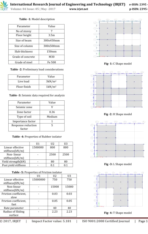
Table -1: Model descriptionParameter Value
No of storey 7
Floor height 3.5m
Size of beam 300x450mm Size of column 300x500mm Slab thickness 150mm Grade of concrete M30
[image:2.595.66.256.112.259.2]Grade of steel Fe 500
Table -2: Preliminary load considerations
Parameter Value
Live load 3kN/m2
Floor finish 1kN/m2
Table -3: Seismic data required for analysis
Parameter Value
Seismic zone V
Zone factor 0.36
Type of soil Medium Importance factor 1 Response reduction
[image:2.595.64.252.292.344.2]factor 5
Table -4: Properties of Rubber isolator
U1 U2 U3
Linear effective
stiffness(kN/m) 1500000 800 800 Non- linear
stiffness(kN/m) - 2500 2500
Yield strength(kN) - 80 80
Post yield stiffness - 0.1 0.1
Table -5: Properties of Friction isolator
U1 U2 U3
Linear effective
stiffness(KN/m) 15000000 750 750 Non-linear
stiffness(KN/m) - 15000 15000
Friction coefficient,
slow - 0.03 0.03
Friction coefficient,
fast - 0.05 0.05
Rate parameter - 40 40
Radius of Sliding
surface - 2.23 2.23
Fig- 1: C Shape model
[image:2.595.66.254.379.484.2]Fig -2: H Shape model
Fig -3: L Shape model
[image:2.595.32.542.439.790.2]© 2017, IRJET | Impact Factor value: 5.181 | ISO 9001:2008 Certified Journal
| Page 1636
3. RESULTS AND DISCUSSION
In this study, the comparison between the fixed base structure and the base isolated structure is done. Also parameters such as time period ,base shear, storey displacement and storey drift of C shape,H shape, L shape, and T shape building with fixed base and with isolators are analysed along X &Y direction.
3.1 C shape building
The C shaped building is constructed as per given building details given in table 1,2,3 and isolators are provided with the properties of rubber and friction isolator that has been given in table 4 &5
Time period
Modal period of fixed base, Rubber Isolator & Friction isolators structures were compared.
Chart -1: Comparison of Time Period in fixed base and isolated base building
Base shear
Base shear in fixed base and base isolated building with rubber and friction isolators in X & Y direction are shown.
Chart -2: The base shear X- direction
Chart -3: The base shear in Y-direction
Storey displacement
Storey displacement in fixed and,with rubber and the friction isolator in X&Y direction are shown.
Chart -4:The storey displacement in X direction
Chart -5: The storey displacement in Y direction
Storey drift
© 2017, IRJET | Impact Factor value: 5.181 | ISO 9001:2008 Certified Journal
| Page 1637
Chart -6:The storey drift, in X directionChart -7:The storey drift, in Y direction
3.2 H shape building.
The H shaped building is constructed by using building details given in table 1,2,3 and with the properties of rubber and friction isolator given in table 4 &5.
Time period
Modal period of fixed base, Rubber Isolator & Friction isolators structures were compared.
Chart -8: Comparison of Time Period in fixed base and isolated base building
Base shear
Base shear in fixed base and base isolated building with rubber and friction isolators in X & Y direction are shown.
Chart -9: The base shear X- direction
Chart -10: The base shear Y- direction
Storey displacement
Storey displacement in fixed and,with rubber and the friction isolator in X&Y direction are shown.
Chart -11: The storey displacement in X direction
© 2017, IRJET | Impact Factor value: 5.181 | ISO 9001:2008 Certified Journal
| Page 1638
Storey drift
Storey drift in fixed and base isolated building ie,with rubber and the friction isolator in X&Y direction are shown.
Chart -13:The storey drift, in X direction
Chart -14:The storey drift, in Y direction
3.3 L shape building.
The L shaped building is constructed by using building details given in table 1,2,3 and with the properties of rubber and friction isolator given in table 4 &5.
Time period
Modal period of fixed base, Rubber Isolator & Friction isolators structures were compared.
Chart -15: Comparison of Time Period in fixed base and isolated base building
Base shear
Base shear in fixed base and base isolated building with rubber and friction isolators in X & Y direction are shown.
Chart -16: The base shear X- direction
Chart -17: The base shear Y- direction
Storey displacement
Storey displacement in fixed and,with rubber and the friction isolator in X&Y direction are shown.
© 2017, IRJET | Impact Factor value: 5.181 | ISO 9001:2008 Certified Journal
| Page 1639
Chart -19: The storey displacement in Y directionStorey drift
Storey drift in fixed and base isolated building ie,with rubber and the friction isolator in X&Y direction are shown.
Chart -20:The storey drift, in X direction
Chart -21:The storey drift, in Y direction
3.4 T shape building.
The T shaped building is constructed by using building details given in table 1,2,3 and with the properties of rubber and friction isolator given in table 4 &5.
Time period
Modal period of fixed base, Rubber Isolator & Friction isolators structures were compared.
Chart -22: Comparison of Time Period in fixed base and isolated base building
Base shear
Base shear in fixed base and base isolated building with rubber and friction isolators in X & Y direction are shown.
Chart -23: The base shear X- direction
Chart -24: The base shear Y- direction
Storey displacement
© 2017, IRJET | Impact Factor value: 5.181 | ISO 9001:2008 Certified Journal
| Page 1640
Chart -25: The storey displacement in X directionChart -26: The storey displacement in Y direction
Storey drift
Storey drift in fixed and base isolated building ie,with rubber and the friction isolator in X&Y direction are shown
Chart -27:The storey drift, in X direction
Chart -28:The storey drift, in Y direction
4. CONCLUSIONS
In the present study, an attempt is made to compare the results obtained from Time History Analysis. Different models of G+6 storey of fixed base, rubber isolated and friction isolated buildings are modeled in Etabs. The seismic analysis is carried out taking into consideration that the buildings are located in zone V. The base shears, storey displacement,storey drift, time period are plotted and compared with C shape,L shape,H shape and T shape buildings model..The major conclusions drawn from the present study are as follows:
From the tables and graphs of storey displacement of isolated and fixed base building of C shape ,L shape, H shape and T shape buildings , it is clear that the storey displacements are much higher for isolated buildings. The isolator with friction has more displacement compared to rubber isolator. The base shear in X-direction & Y-direction it is
reduced by Rubber isolator and friction isolator. And it is obtained from the graph and the table that is plotted for the C shape ,L shape, H shape and T shape buildings. And identified that the Friction isolator will better to reduce the base shear than using Rubber isolator.
Time period of both the base isolated structures i.e. Rubber and Friction isolator increases as compared to the fixed base structure. Friction isolator has got greater increase in time period than Rubber isolator.The increment value in time period while using the isolation system is obtained from the graph and table that is ploted for C shape ,L shape, H shape and T shape buildings on each mode. Results from storey drift that is obtained for C shape
© 2017, IRJET | Impact Factor value: 5.181 | ISO 9001:2008 Certified Journal
| Page 1641
REFERENCES
[1] Prof.R.B.Ghodke, Dr.S.V.Admane, “Effect Of Base-Isolation For Building Structures”, International Journal of Science, Engineering and Technology Research (IJSETR) , vol 4, April 2015,pp. 971-974.
[2] Sonali Anilduke1, Amay Khedikar2, “Comparision Of Building For Sesmic Response By UsingBase Isolation”, International Journal of Research in Engineering and Technology, vol 6 , June-2015,pp. 237-241
[3] Naveen K1, Dr. H.R Prabhakara2, Dr. H Eramma3 , “Base Isolation Of Mass Irregular Rc Multi-Storey Building”, International Research Journal of Engineering and Technology (IRJET) ,vol 7 , Oct-2015,pp. 902-906 [4] Ashish R. Akhare*1, Tejas R.Wankhade2, “Seismic
Performance of RC Structure Using Different Base Isolator”, International Journal Of Engineering Sciences & Research technology,vol 5, May 2014,pp. 724-729 [5] Chandak N. R, “Effect of Base Isolation on the Response
of Reinforced Concrete Building”, Journal of Civil Engineering Research, vol 4, .2013,pp.135-142. [6] IS 1893 (part 1): 2002, commentary “Criteria for
Earthquake Resistant Design of Structures”. BIS, New Delhi