© 2017, IRJET | Impact Factor value: 5.181 | ISO 9001:2008 Certified Journal
| Page 61
Crane Hook Design and Analysis
G Bhagyaraj
1, K Suryaprakash
2, K Subba Rao
31
M.Tech. CAD/CAM, Godavari Institute of Engineering and Technology, Rajahmundry
2
Associate Professor, Godavari Institute of Engineering and Technology, Rajahmundry
3
Head of Department, Godavari Institute of Engineering and Technology, Rajahmundry
---***---Abstract -
Hoists and cranes have a very important role inmany sectors of various industries like the logistics, in ship building industries, steel industries, some transport vehicles, etc., for lifting loads and carry them. Many types of hooks having different ratings and sizes are used according to the specified objective. The types of hooks used are based on the type of hoist or the type of crane to which they are attached. This paper aims at building a 245 KN or 25-ton resistant block hook with a hook made up of using lead alloy in the market, Alloy 1.2367 (X38CrMoV5-3), which have high tensile strength, compression strength, and yield strength compared to the presently used alloy in the manufacturing of crane hooks. The design of block hook and its components is done in Solidworks Part Design and the individual components are assembled in the Solidworks assembly. The analysis on the hook using the Alloy 1.2367 (X38CrMoV5-3) is carried out in Solidworks Simulation. The images are rendered using Solidworks Visualize.
Key Words: Alloy 1.2367 (X38CrMoV5-3), Block Hook, Crane, Hook
1.INTRODUCTION
The hooks used in hoists and various types of cranes play a major role in lifting the heavy loads in many sectors, industries, oil rigs, vehicles, etc. The performance of the hook depends on its load rating. Even though the hook may have high load rating, the failure of the hooks has many reasons such as the bearing used in the hook block, types of fastening system by which they are fastened to the hoists or cranes, materials used in the design of the hook, etc.
The hooks used for heavy loads also need to be large, big, huge and heavy in order to function safely at the prescribed loads. Due to this various types of researchers are taking place in the field of manufacturing of hooks such as process by which they are manufactured, metallurgy involved in the manufacturing, etc., in order to reduce the size, cost of manufacturing and to increase the flexibility in the usage of the hooks which can be used for high loads.
The present paper aims at building a hook by using the small shape in its design which can withstand heavy loads than the presently available hooks in the market for the same standards and rating.
The design process of crane hook and the analysis process of crane hook using the Alloy 1.2367 (X38CrMoV5-3) are detailed. Results such as Von Mises stress, Factor of Safety (FOS), Strain and Displacements are also discussed.
2. GOVERNING THEORY
The strategy utilized as a part of the geometric simulations of design in Solidworks Simulation is the Finite Element Analysis (FEA). Finite Element Analysis utilized as a part of simulation software or solvers, for the most part, includes three stages. They are as per the following:
A. Pre-processing: In this progression, the finite element mesh for the designed model is produced and boundary conditions, material properties, and loads are applied to the composed model.
B. Solution: In this progression, the solutions for the problems for the given loads and boundary conditions. The outcomes, for example, Von Mises stress, displacements, strain, thermal impacts, and so on., are acquired in this progression.
C. Post-processing: In this progression, the results are pictured as contours, deformed shapes, and plots. This progression helps in the investigating, confirmation and approval of results.
3. MATERIAL PROPERTIES
The Alloy 1.2367 (X38CrMoV5-3) which is used in the study of crane hook has the following material properties which are represented as Table1.
Table -1:
Properties Alloy 1.2367
Yield strength 2.12e+009N/m2
Tensile strength 2.12e+009N/m2
Elastic modulus 2.15e+011N/m2
Poisson's ratio 0.28
Mass density 7850kg/m3
Shear modulus 7.9e+010N/m2
Thermal expansion
© 2017, IRJET | Impact Factor value: 5.181 | ISO 9001:2008 Certified Journal
| Page 62
4. METHODOLOGY
In Solid works Part design the hook and the block components are designed. The hook and its components are assembled in Solid works assembly. The modelled hook is analysed in Solid works Simulation.
4.1
Hook Design
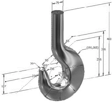
The hook is modelled in Solid works Part design. Figure 1 shows the isometric view of the hook and its dimensions.
Fig -1: Hook Isometric View
[image:2.595.342.524.95.220.2]The volumetric properties of the hook modeled using Solidworks with the Alloy 1.2367 (X38CrMoV5-3) are shown in Table 2.
Table -2:
Design With Alloy
Mass Volume Density Weight
Alloy 1.2367 (X38CrM oV5-3)
9.0659 1 kg
0.0011548 9
m3
7850 kg/m3
88.8459 N
4.2
Block Hook Assembly
The hook and its components are assembled in Solidworks assembly to form a block hook. The isometric view of the block hook rendered using Solidworks Visualize is shown in Figure 2 and the exploded view of the block hook rendered using Solidworks Visualize is shown in Figure 3.
Fig -2: Block Hook Isometric View
Fig -3: Block Hook Isometric View
4.3
Hook Meshing Details
[image:2.595.42.230.252.424.2]Table 3 shows the mesh type, type of mesh element used in the models meshing, Jacobian points and solver type used in the boiler shell simulation and analysis in Solidworks Simulation software.
Table -3:
Type of Mesh Solid mesh
Type of Mesh
Element Tetrahedron
Jacobian points 4
Type of Solver FFEPlus
Table 4 gives the detailed meshing information of the hook analysed using the Alloy 1.2367 (X38CrMoV5-3).
Mesh Details Alloy 1.2367
Type of Mesh Solid mesh
Type of Mesh Element Tetrahedron
Jacobian points 4
Size of Element 5.24417 mm
Tolerance 0.262208 mm
Total Nodes 68096
Total Elements 45438
Maximum Aspect
[image:2.595.308.560.255.370.2] [image:2.595.329.540.509.589.2] [image:2.595.40.287.523.618.2]© 2017, IRJET | Impact Factor value: 5.181 | ISO 9001:2008 Certified Journal
| Page 63
5. RESULTS AND DISCUSSIONS
The simulation studies conducted on the crane hook using the Alloy 1.2367 (X38CrMoV5-3) for its sustainability against loading gives the results such as Von Mises stress, Factor of Safety (FOS), Strain and Displacements. The test conditions and the results are as follows:
5.1
Test Conditions
In this study conducted on the crane hook, the applied load value is equal to mg which is the weight of the crane hook. Here m is total mass of the crane hook and g is acceleration due to gravity. The force load is applied on the C- section of the crane hook in the direction of the gravity. Bolted supports at the bolt hole of the crane hook is used as fixtures on which the complete weight of the crane hook acts. The results of the crane hook analysis in the study using the materials Alloy 1.2367 (X38CrMoV5-3) are shown in Table 5, Table 6, Table 7 and Table 8.
The analysis criterion and the test conditions are:
The crane hook has mass m = 9.06591kg when analyzed with
Alloy 1.2367 (X38CrMoV5-3). Acceleration due to gravity which is equal to g = 9.8 m/s2 causesthe load L = 88.8459N when analyzed with Alloy 1.2367 (X38CrMoV5-3). Force load of F = 245 KN or 25 t is used on the inner C – section of the crane hook.
Von Mises stress failure criterion, URES Displacement criterions are used in the study.
[image:3.595.311.555.162.298.2]5.2
Results
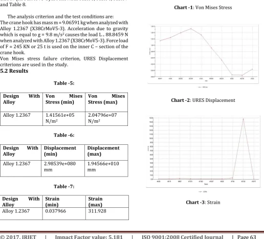
Table -5:
Design With
Alloy Von Stress (min) Mises Von Stress (max) Mises
Alloy 1.2367 1.41561e+05
N/m2
2.04796e+07
N/m2
Table -6:
Design With
Alloy Displacement (min) Displacement (max)
Alloy 1.2367 2.98539e+080
mm 1.94566e+010 mm
Table -7:
Design With
Alloy Strain (min) Strain (max)
Alloy 1.2367 0.037966 311.928
5.3
Plots
The plots obtained by using the probe tool are shown in Chart 1, Chart 2, Chart 3, and Chart 4.
Chart -1: Von Mises Stress
Chart -2: URES Displacement
[image:3.595.36.553.323.790.2]© 2017, IRJET | Impact Factor value: 5.181 | ISO 9001:2008 Certified Journal
| Page 64
Chart -4: Factor of Safety5.4
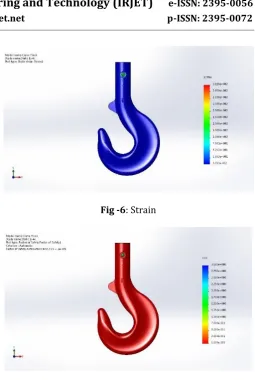
Surface Plots
The results are shown on the surface of the crane hook which is called surface plots or contours.
Figure 4, Figure 5, Figure 6 and Figure 7 represents the surface plots on the crane hook.
Fig -4: Von Mises Stress
Fig -5: URES Displacement
Fig -6: Strain
Fig -7: Factor of Safety
5.5
Interpretation of Results
From the results of the simulations studies conducted on the crane hook, it can be observed that the result values, minimum Von Mises stress, and the maximum Von Mises
stress are very less compared to the Yieldstrength ofthe
Alloy 1.2367 (X38CrMoV5-3). Therefore, the design, crane hook is hence considered to be successful.
6. CONCLUSIONS
The design of crane hook is successful since the values minimum and the maximum Von Mises stress are very less
compared to the Yieldstrength of Alloy1.2367
(X38CrMoV5-3).
[1] The maximum value of the Von Mises stress of the
crane hook in the studies is 2.04796e+07 N/m2 for the
Alloy 1.2367 (X38CrMoV5-3) whose yield strength value is 2.12e+009 N/m2.
[2] From this study, we can conclude that the replacement
[image:4.595.53.564.44.442.2] [image:4.595.305.561.53.434.2] [image:4.595.39.279.108.233.2] [image:4.595.42.544.353.782.2]© 2017, IRJET | Impact Factor value: 5.181 | ISO 9001:2008 Certified Journal
| Page 65
[3] The use of Alloy 1.2367 (X38CrMoV5-3) also results in
reduced mass and can also be mounted to various cranes and hook blocks without changing the design of the hook.
REFERENCES
[1] Deborah L Boklund Moran, “Hook Assembly and Kit,”
United States Patent, Patent No.: US 20060289714 A1.
[2] John Joseph Rinaldo, “Pot Rack Hook,” United States Patent, Patent No.: US 20120199714 A1.
[3] Dominique Rouzaud, “Safety Locking Device Having a
Rocking Hook,” United States Patent, Patent No.: US 005257840 A1.
[4] Ralf Esising, Gersemsky, Lichtenvort, Walloschek, “Load Hook,” United States Patent, Patent No.: US 20070176446 Al.