ANALOG COMPUTER
INFORMATION MANUAL
For
The EAI 231R-Y
ii
COPYRIGHT EL.ECTRONIC ASSOCIA TESt INC. 1964 AL.L. RIGHTS RESERVED
Preface
CONTENTS
Page
INTRODUCTION ... 1
CONTROL CONSOLE ... 5
Program Patching System ... 6
Automatic Extended Read Out (AERO) System ... 6
Digital Attenuator System (DAS) ... 9
Problem Check System ... 10
Overload Indicator System ... ' ... 11
MODE CONTROL ... 13
Integrator Mode Control ... ... M • • • • 13 Real- Time (Relay) Mode Control ... ... 15
High-Speed (Electronic) Mode Control ... 16
Mode Logic Programming ... 16
Logic Conversion ... 18
Time-Scale Programming ... 18
COMPUTING COMPONENTS ... 21
Operational Amplifiers ... 21
Amplifier Networks ... 22
summer-integrators ... 23
summers ... 23
analog memory units ... 23
passive elements ...
24
Coefficient Attenuators ... 25
manual attenuators ... 25
servo-set attenuators ... 26
Servo Multipliers and Resolvers ... 26
servo multipliers ... 26
servo resolver-multipliers ... 30
potentiometer padding units ... 31
Electronic Multipliers and Resolvers ... 31
electronic multipliers ... , ... 31
electronic resolvers ... 32
Diode Function Generators ... 35
arbitrary diode function generators ... 35
fixed diode function generators ... 36
diode limiters ... , ... 38
Switching Devices ... 38
electronic comparators ... 39
function relays ... 39
digital-to-analog switches ... 39
function switch~s ... 40
Noise Generators ... 40
PERIPHERAL EQUIPMENT ... 43
Automatic Digital-Input-Output System (ADIOS) ... 43
Repetitive Operation Display Unit ... 44
Strip Chart Recorder ... ~ ... 45
x-
Y Recording Equipment ... 47Oscilloscopes ... 48
COMPUTER TEST EQUIPMENT ... 49
Maintenance Test Console ... 49
Preventive Maintenance Check (PMC) Panels ... 49
Miscellaneous Test Equipment ... 52
COMPUTATION SERVICES ... 53
Training ... 53
Maintenance ... 54
INTRODUCTION
Complex system designs dictate the constant need for thorough investigations of system behavior over wide ranges of operating conditions. Such investi-gations generally consist of an interwoven series of experiments and analyses to determine the effect of individual parameters on overall performance. Since the cost and complexity of modern systems preclude the use of scale models or prototypes for this pur-pose, the design-engineer/ scientist must rely on a mathematical model, or statement of laws governing
system behavior.
Electronic computers provide the engineer with a means to obtain accurate solutions - rapidly - to these mathematical relationships without the uncer-tainty of results inherent in other procedures. The computer makes it possible to perform controlled experiments and design modifications in a fast, safe, economic manner - by simulation. Because of this, computer simulation has become an integral part of, and a routine technique in, complex system design and development.
The success of this procedure is dependent on the selection of a scientific computer that is suited to the needs of the simulation. Speed and accuracy re-quirements vary with the system to be investigated and the information required. The capability to simu-late only static or steady-state conditions - as well as complete system dynamics must also be considered.
The dynamic behavior of a physical system is characteristically described by differential equations, which lend themselves to high-speed solutions by an electronic differential analyzer - or general-purpose analog computer. The solution speed of the analog computer becomes even more important when a portion of the actual physical system is involved, or when "real-time" simulation is necessary.
As systems become more complex, the mathematical models require more sophisticated simulation tech-niques and methods of analysis - thus the computer must provide capabilities for utilizing new tech-niques. The need for more complete mathematical descriptions of systems has placed particular em-phasis on the computer solution of partial differ-ential equations. Advanced solution techniques for such equations, which make use of sequential or iterative operations, have made it necessary to ex-tend the computing speed range of the analog com-puter to permit "compressed time" or faster than "real-time" simulation. Use of the analog com-puter to perform automatic system optimization in accordance with specific design criteria imposes further requirements - such as logical decision-making and control.
The technology of the space age has brought about a need for analysis of systems which involve both dis-crete and continuous phenomena. Simulation of such systems dictates the need for a computer capable of
performing the continuous (analog) and the discrete (digital) operations. Simulation of the combined dynamic and steady-state characteristics of a sys-tem, particularly if the latter requires logical de-cisions or extreme precision, further suggests the use of a "hy brid" computer to effectively integrate the capabilities of analog and digital equipments. To meet this challenge EAI introduced the 231R-V General-Purpose Analog Computing System. This system exhibits the accuracy and stability neces-sary for real-time simulation, and at the same time provides the solution-speed and control flexibility necessary for iterative and hybrid computation. The 231R- V is the latest in the 231R series of analog computing systems, and as such, makes use of a basic design which has achieved an unmatched re cord for performance and reliability. Incorporating all of the proven features of previous PACE com-puters, the 231R .. V adds many advanced features specifically designed to meet the simulation require-ments of industrial and government research and development groups.
Among the many new features offered by the 231R-V is the EAI Analog Memory and Logic System, which allows the computer to perform the functions of mode control, signal switching and storage under program control at repetitive operation speeds. Electronic mode control, i.ndividual integrator time-scale selection, and high-speed analog memory make possible multi-speed and iterative operation of the computer. The modular design of the 231R-V allows the customer to initially establish a modest-sized installation and later expand as the work load and problem complexity dictate. Provisions for mode control slaving and signal communication between multiple 231R Computing Systems permit expansions necessary to cope with the largest simulation problems.
EAI Computation Centers offer a complete curricu-lum of training courses in the proper maintenance, operation, and programming of analog and hybrid computers. Advanced courses are given on analog and hybrid computation, covering such fields as chemical process, aerospace and biochemical simu-lation. The computation center installations are also available to industry to provide the latest in scien-tific computers and programming techniques for tasks ranging from operations research to the solu-tion of partial differential equasolu-tions.
As the leading supplier of general-purpose analog and hybrid computing systems, EAI also offers the
2
most extensive supporting services to assure the success of a computing facility. The largest field service organization in the analog computer industry is available to supply information and assistance to customer maintenance personnel, or to provide com-plete maintenance service under a contract tailored to the specific customer's requirements.
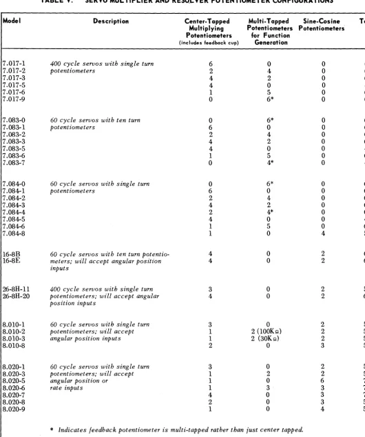
TABLE
I.
EQUIPMENT COMPLEMENT OF FULLY EXPANDED 231R-VOPERATIONAL AMPLIFIERS
Summer-Integrators ... . Summers ... .. Summers with Track and S~Qre Network ... .. Summer-Inverters ... .. Inverters associated with Diode Function Generators ... .. Inverters associated with Electronic Multipliers ... .. Inverters associated with Electronic Resolvers ... . Additional Amplifiers associated with Electronic Multipliers ... . Additional Amplifiers associated with Electronic Resolvers ... .
Total COE FFICI ENT POTENTIOMETERS
Manual Attenuators ... . Manual or Servo-Set Attenuators ... ..
Total
ELECTRONIC MULTIPLIERS ... __ .. . NONLINEAR COMPONENT POSITIONS (See Note 1) ... .. ELECTRONIC RESOLVERS (See Note 2) ... . DIODE FUNCTION GENERATORS (Manual or Servo-Set) ... .. DIODE LIMITERS (Bridge or Feedback) ... . COMBINATION TRACK & HOLD UNITS (See Note 3) ... .. DIGITAL-ANALOG SWITCHES ... .. ELECTRONIC COMPARATORS (With Function Relays) ... .. POTENTIOMETER PADDING UNITS (See Note 4) ... .. MODE LOGIC PROGRAMMING COMPONENTS
Interval Timers ... . Function Switches ... .. Mode Relay Drivers ... .. Repetitive Drives (See Note 5) ... . Logic Gates ... . PASSIVE ELEMENTS (See Note 6)
Resistors ... . Capacitors ... .
Total
FUNCTION SWITCHES ... . EXTERNAL TRUNK LINES
Input and Output Trunks on Analog Patch Panel ... .. Input and Output Trunks on Mode Logic Patch Panel ... ..
Total
INTER-PANEL TRUNKS (See Note 7) ... .. HYDAC DIGITAL OPERATIONS SYSTEM INTERFACE TERMINATIONS
Electronic Comparators ... .. Digital-Analog Switches ... . Mode Relay Drivers ... . ELECTRONIC DIGITAL VOL TMETER ... . VACUUM-TUBE VOLTMETER ... " ... .. AUTOMATIC DIGITAL INPUT-OUTPUT SYSTEM (ADIOS) ... .. HIGH-SPEED PRINTER ... . GAUSSIAN NOISE GENERATOR ... . EIGHT-CHANNEL RECORDERS ... .. X-Y PLOTTERS ... . CURVE-FOLLOWER FUNCTION GENERATORS ... . HIGH-SPEED REPETITIVE OPERATION DISPLAY CONSOLE (EIGHT-CHANNEL) ... .. MONITOR OSCILLOSCOPE ... .
NOTE 1. A Non-linear Component Position may accommodate any of the following equipment: (a) one Servo-Multiplier
(b) one Servo-Resolver-Multiplier
(Cj
four 1800
J'ine-Cosine Generators (d three 360 Sine-Cosine Generators(e six Fixed Function Generators (Log X, X2, X4) in any combination (f) three Electronic Multipliers
Qty.
30
29
165
4030
1230
24 --m-20 150 17030
6 3 20 15 10 12 10 9 2 6 104
11 10 10-W
20 200 40 240 8 1630
8 1 1 1 1 1 2 3 3 1 1NOTE 2. Each Electronic Resolver contains four Electronic Multipliers and one Sine-Cosine Generator that maybe used in-dependently of the Resolver. It is also possible to have two additional Electronic Resolvers in place of two of the Non-linear Component Positions.
The individual Combination Track and Hold Unit consists of an Electronic Comparator and two Track and Hold networks which may be used as digital-to-analog switches.
NOTE 3.
NOTE 4. NOTE 5.
NOTE 6. NOTE 7.
Additional Potentiometer Padding Units may be supplied as customer needs dictate.
The three Repetitive Drives, 250cps, 500cps and 2500cps, are available when the computing system contains a High-Speed Repetitive Operation Display Console.
Patch cords containing resistors, capacitors and diodes are available as needed.
4
:I ~ ~ "~.r >¥ .r It,. .. ~ .)~" .. ~'" #HI!) #U, ¥liff"~
",. "J~ 'Hib""""."'_ti l, ..
'-.. ~#W"Ii.tii"!~""'''''''<8''''''
"Ii I.~ "'* "'I"'~
"'f f';H"'~ h'f ~(;j 'j~ b l ' If""'~ ',"""J f''*h'. '.I#I'jN".'/Ii .... '_~ ... ~,.'U • .,.")".,, ... , ... o!tf',; 4 ~ ... "'1 IH~ hI>; I."'t '~If I,,# ... ~ , ) ,j ,.,~ ,~ ... ~,~ hl'-'ft 'J', ,. It '~" ~". Ifh #J~~ .#~~~.J~ ,;i~
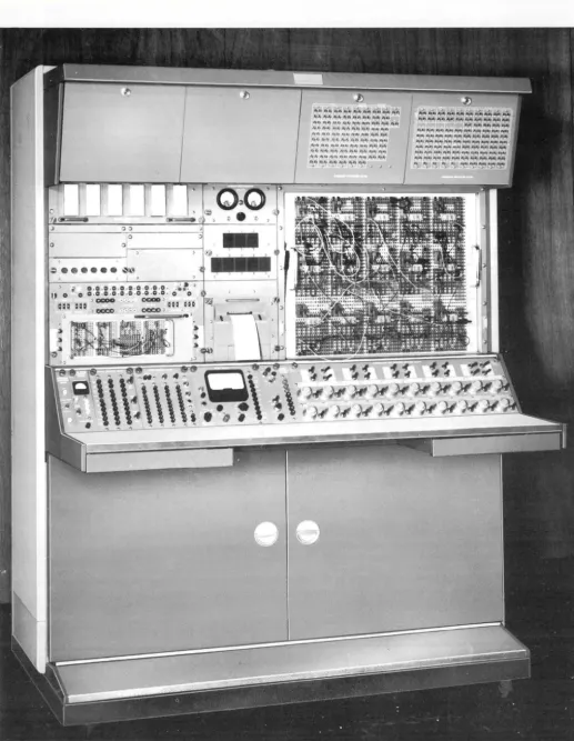
[image:11.623.41.558.40.706.2]CONTROL
The PACE 231R-V Analog Computing System (Figure 1) is a general-purpose computer for simulating dynami c systems . . . yielding new standards for speed, accuracy, reliability and economy in the scientific computing field. Over two hundred operational amplifiers enable the 231R-V to handle everything from routine engineering calculations to the most complex and sophisticated problems in system design. The modular arrangement of elements in this computing system permits field expan
-sion of an installation to cope with increasing problem complexities as needed.
DESCRIPTION
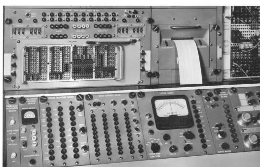
The programming and control center of the 231R-V is a three-bay console-type cabinet (Figure 2) containing the operating controls and program patching system for the entire computer.
In
addition, the linear computing com-ponents, i.e., integrators, summers, coefficient attenu
-ators, etc., together with their associated power supplies and temperature-stabilized network oven, are included in this cabinet. Completely useable as a self-contained linear computing system, the control console may be later expanded to include the capability for solving more complex non-linear problems. Multipliers, function generators and other non-linear components are contain-ed in separate cabinets which are physically joined to the console, the interconnecting cables being routed through an integral cable duct at the rear of the cabinets.
CONSOLE
Table I lists the equipment complement of a fully
-expanded 231R-V System. Further expansion may be accomplished by the addition of a second control console with ~ts associated expansions.
Special consideration has been given to human-engineer
-ing the 231R-V Control Console for maximum operator convenience and efficiency. All programming and con-trol functions are centrally located at the console. Controls which include the readout selector pushbuttons, Digital Attenuator System input keyboard, vacuum-tube voltmeter, and mode control pushbuttons, are conveniently grouped on a sloping panel (Figure 3) which spans the front of the console. All controls and indicators are clearly labeled according to the functions which they serve. Also mounted on this panel are twenty function switches and tw~nty manual coefficient attenuators, to facilitate program checkout and problem parameter ad-justment, Immediately above the control panel are the program patching system, digital voltmeter, printer, and the Analog Memory and Logic System control unit with its associated patching system. Mounted below the control panel, a shelf with storage drawers provides a convenient work area for the operator. The entire con
-trol and patching area of the console is illuminated with indirect fluorescent lighting.
[image:12.628.46.574.383.722.2]Figure 4. Program Patching System
PROGRAM PATCHING SYSTEM
Since a significant portion of the overall computing cycle for a general-purpose analog computer is devoted to programming, emphasis has been placed on the design of the 231R-V Program Patching System (Figure 4). It features a 3,450-hole removable pre-patch panel and
patch-bay which permit program patching without
interrup-tion of computer operainterrup-tion. Patching changes may be made without removing the panel from the computer;
moreover, patch panels may be interchanged in seconds
with complete assurance of electrical continuity on all contacts.
The all-metal pre-patch panel of the 231R-V is precision-machined for accurate alignment with the patchbay
-Figure 5 Figure 6
Close-up of Pre-Patch Panel. Close-up of Patch-Bay Contacts
6
the use of an aluminum alloy insuring a durable,
light-weight, easy-to-handle panel. Low-cost construction makes practical the purchase of a number of spare panels for long-term program storage. Patching terminations (Figure 5) are color-coded and labeled with large, cle ar lettering to facilitate error-free patching. A unique, modular format, which arranges locations of computing-component group terminations to conform with a typical patching sequence, permits maximum use of bottle plugs - thus reducing patch cord clutter. Write-in areas on the panel enable identification of stored
pro-grams. A complete variety of fully-shielded patch
cords, bottle plugs and other patching accessories are available for use with the pre-patch panel. Patch cords containing resistors, capacitors, diodes, and special networks may also be supplied.
With the inputs and outputs of all computing components
terminating at the patch-bay, its electrical design is necessarily critical to the performance of the computer; i.e., special care must be taken to prevent cross-talk and to avoid degrading the accuracy of computing volt-ages. To minimize noise and allow maximum dynamic performance of computing components, the 231R- V patch-bay includes complete electrical shielding for each signal. A metal gridwork (Figure 6) on the front and
rear of the patch-bay forms individually shielded cells
for each contact. Moreover, each contact is mounted on a low-loss insulator bushing. To minimize the conduct
-ing paths between the pre-patch panel and amplifier net-works, the patch-bay also forms the front cover of the temperature-stabilized network oven. All electri cal connections to the rear of the patch-bay are made either by taper pins or banana plugs to facilitate maintenance and permit modification of patching terminations.
The latching mechanism which locates the panel in the patch-bay includes a system of cams to create a wiping action between the patch cord tips and contact springs of the patch-bay. To assure minimum contact resistance,
the cord tips and patch-bay springs are gold-plated by a special process. For safety, the latching system
in-cludes provisions for automatically disconnecting all voltages from the contacts when the pre-patch panel is
removed.
AUTOMATIC EXTENDED READ OUT (AERO) SYSTEM The overall usefulness of an electronic computer is greatly determined by its input-output capabilities and
its provisions for operator-machine communication. Throughout the programming phase of an analog computer it is particularly important that the operator be able to
readily select and monitor voltages in the program. This
is accomplished in the 231R-V by the Automatic Extend-ed Read Out (AERO) System which offers both manual
and automatic selection of components.
In
addition to readout of computing component outputs, provisions are included for monitoring integrator initial derivatives and coefficient attenuator settings. A com-plete list of the signals selected by the AERO System is given in Table
II.
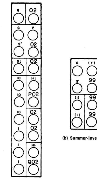
The voltage values of these sigvolt-TABLE
II.
SIGNALS MONITORED BY THE FULLY EXPANDED 231R.V READOUT SYSTEMCOMPONENT CATEGORY
Operational Amplifiers
Coefficient Potentiometers
Electronic Multipliers
Servo Multipliers
Servo Resolvers
Electronic Resolvers
Diode F unction Generators
Electronic Comparators
Trunks
READOUT SIGNALS
Summer-Integrator Outputs Integrator Initial Derivatives Summer Outputs
Summer-Inverter Outputs
Outputs of Summers with Track and Store Networks
Outputs of Inverters associated with Diode Function Generators Outputs of Amplifiers associated with Electronic Multipliers Outputs of Amplifiers associated with Electronic Resolvers
Potentiometer Coefficients Potentiometer Outputs
Electronic Multiplier Outputs Associated Amplifier Outputs
Feedback Potentiometer Outputs Multiplying Potentiometer Outputs
Feedback Potentiometer Outputs Multiplying Potentiometer Outputs Sine-Cosine Potentiometer Outputs
Electronic Resolver Outputs Sine-Cosine Generator Outputs Electronic Multiplier Outputs
Outputs of Amplifiers associated with Electronic Multipliers
Function Generator Outputs Associated Amplifier Outputs
Function Relay Arms
Input Trunks
meter or electronic digital voltmeter; a high-speed digital printer provides a printed record of voltages measured by the digital voltmeter.
The AERO signal selector makes use of high-speed stepping relays equipped with gold-plated contacts to insure low-loss signal paths. These relays are address-ed manually with the parallel-input keyboard (Figure 7), or automatically from the ADIOS (Automatic Digital
Figure 7. AERO Signal Selector
The Electronic Digital Voltmeter (EDVM) is a precIsion
readout device which provides rapid and extremely ac-curate visual display of analog voltages in digital form.
The high conversion speed permits almost instantaneous reading of slowly varying voltages - reducing the time required for adjusting manual coeffi cient atten u a tors dIld diode function generators. The EDVM (Figure 8)
pro-vides an in-plane projection-type display of the signal
voltage and the address designation of the component
()
o
o
A 5
!
I3
o
Q
o
o
+1 1 9 3 6
o
Figure 8. EDVM Display
8
v V
·
v <.. <.. . jT 3
8
·
+I
·
0
0
0
0
T 3
7
+0
·
2
2
5
2
T
3
6
+I
·
0
0
0
0
T
3
5
·
+0
2
2
5
0
T 3
4
·
+0
·
9
9
9
9
T 3
3
·
+0
2
2
5
IT
3
2
...
0
9
9
9
9
T 3
I
+0
4
0
0
IT 3
0
+0
·
9
9
9
9
T
2
9
·
+0
4
0
0
0
T
2 8
·
+0
9
9
9
9
T 2 7
+0
·
8
0
0
0
T 2 6
·
+0
·
9
9
9
9
T
2
5
+0
·
8
0
0
IT 2
4
+0
·
9
9
9
9T 2
3
-
0
·
6
0
0
IT
2
2
·
-
I·
0
0
0
IT 2
I·
+0
8
0
0
0
T
2
0
+ I0
0
0
0
T
,
9
-
0
·
6
0
0
0
T
I
8
·
-
I0
0
0
IT
I 7-
0 6 () () (Figure 9. Printer Tape Listing
selected. A unique input circuit maintains an extremely
high input impedance to minimize current loading effects on the accuracy of the readings. Automatic polarity indication and twenty per-cent over-ranging further
extend the usefulness of the EDVM.
In order to obtain a complete readout of all components
in the computer, the AERO System includes an automatic scanning cycle for use with the high-speed digital
printer. The printer produces an adding machine tape record (Figure 9) of component address designations and output voltage values. Print spacing may be adjusted
to permit operator notation on the tap~.
~--
I
. I
Figure 10. Vacuum-Tube Voltmeter
•
•
•
•
•
The control panel of the 231R-V also includes a vacuu m-tube voltmeter (VTVM) with pre-amplifier for reading small signal values. The VTVM signal selector (Figure 10) monitors power supplies, reference, and the output of the AERO signal selector.
DIGITAL ATTENUATOR SYSTEM
(DAS)
With increased interest in automatic operation of
elec-troni c computers, a greater number of systems are being manufactured wi th servo-set coefficient atte n ua tors.
EAI's 231R-V offers the Digital Attenuator System
(DAS). Used in conjunction with the AERO System, the DAS enables the operator to make automatic selections and adjustments of both servo-set coefficient
attenu-ators and diode function generators. This may be
ac-complished with punched-tape by the Automatic Digital
Input-Output System (ADIOS), or directly from the digital section of the HYDAC System. Provisions are also
included for manual adjustment by means of a
parallel-input keyboard or slave potentiometer.
The servo-set potentiometers are contained in plug-in
drawers which mount in the Control Console, each at-ten ua to r drawer having its own drive motor and selection
system. Separate electrical and mechanical selection
permits interrogation of potentiometers without
mechani-cal engagement - eliminating the possibility of settings
being altered during readout. New settings are
estab-lished through the use of the servo-set potentiometer in
the feedback of an electro-mechanical servo system, where the output of the potentiometer is summed with a
precision input voltage in the servo amplifier.
Figure 11. DAS Input Keyboard
The input to the DAS servo amplifier in the 231R-V is supplied by a Remote-Control Voltage Divider (RCVD) which makes use of relay-selected precision resistors
and the computer reference voltage. The setting of the RCVD is determined by a binary-coded-decimal input to the relays. This input may be provided by a decimal keyboard (Figure ll), the tape-reader of the Automatic Digital Input-Output System (ADIOS), or from the pre
-patch panel of the HYDAC Digital Operations System.
In addition to the automatic and manual adjustment of
servo-set potentiometers with the RCVD, the DAS system includes a slave potentiometer (Figure 12)
which may be used to vary the setting of an attenuator
during computer operation. Once engaged, the slave
potentiometer retains control of the addressed (selected) a tte n u a tOI' until another selection is made, enabling the
operator to observe the effect on the problem solution. Since the input to the DAS servo amplifier may be
switched to a pre-patch panel termination, it is also possible to make use of program voltages for adjusting servo-set potentiometers.
PROBLEM CHECK SYSTEM
To assure correct computer solution of a p·roblem, it is
necessary to determine that the program has been
prop-erly implemented on the computer. This is particularly
important with an analog computer where manual
pro-gramming can result in patching mistakes or incorrectly
-adjusted coefficient attenuators.
Errors of this type may easily be located by means of a
"static check" procedure, which involves comparing calculated values of the problem variables with voltages
measured in the computer program. To perform a check of the entire program, however, it is necessary that all components in the program receive voltage inputs. Since there are usually several integrators which do not have
programmed initial conditions, special provisions must be made available.
The 231R-V includes a static test mode which
estab-lishes a program test condition by automatically intro-ducing initial condition voltages on all integrators which
do not have programmed initial conditions. This is accomplished by means of "test reference" busses on the pre-patch panel which are energized in the static test mode. By patching the voltage outputs of these
busses either directly, or through a potentiometer, to the initial condition (Ie) inputs of the integrators, it is
possible to insure that all computing components
re-ceive voltage inputs.
By means of the digital printer and automatic scanning cycle of the AERO system, the values of the voltages in
the program may be printed out for comparison with cal
-culated or previously measured values. Since the check
output of the AERO system provides for readout of integrator initial derivatives, a complete check of the program patching and operation of the computing
com-ponents is obtained. The static test programming need not be removed from the pre-patch panel since the test reference busses are de-energized in all other computer
modes. This makes it possible to periodically repeat the static test procedure to verify the condition of the program.
~ ~ 0 ~
~. ~IE> ~eJ
~I:-I/» tf. tI!> (io tfp , .. ~
(l ~ C'*~ (j h
'~(:r ( ...
Figure 14. Central Overload Indicator
[image:17.634.37.569.340.678.2]The read-out mode of the Automatic Digital Input-Output System (ADIOS), which permits a comparison of problem voltages with pre-determined values on punched tape, makes it possible to automatically perform the static problem check. The ADIOS typewriter then provides a printed record of the static check complete with calcu-lated and measured values of the problem variables. The ERRORS-ONLY read-out mode of the ADIOS also makes it possible to rapidly locate programming errors. A similar "'problem check" may be accomplished with the HYDAC Digital Operations System.
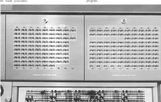
OVERLOAD INDICATOR SYSTEM
Since an electronic device is subject to the saturation or overloading of active components, it is important that the operator be aware of any such condition - - which could result in incorrect operation of the equipment. This is particularly true of an analog computer where, during the course of problem parameter variations, pro-gram voltages may exceed the voltage handling capabili-ties of the components. So that the operator is made aware of such conditions, the 231R Overload Indicator System provides visual and audible indications of component overloads.
The Overload Indicator System uses overload alarm
busses which are activated by component overload-indicating signals. In operational amplifiers, for ex-ample, the indicating signal is actually a departure of the amplifier summing-junction voltage from ground potential. For servo multipliers and resolvers, a null error indicates that the dynamic limitations of the unit are being exceeded. In addition to the overload indica-tion for operaindica-tional amplifiers associated with non-linear components, the Overload Indicator System also includes provisions for indicating the overload of squaring and sine/cosine function generators associated with the electronic multipliers and resolvers.
...
N
MODE CONTROL
Iterative operation of a General Purpose AnalogCom-puter requires sophisticated control of the operating modes. Furthermore, it must be possible to perform the functions of mode selection, signal switching, and storage under program contr ol at repetitive operation speeds. Present programming techniques, based on sampling the results of high-speed calculations for "real-time" problem solutions give rise to a need for multiple time-base operation; moreover, sequential computer operation has brought the need for discreet or digital devices in the analog computer. Such new programming techniques and components are all related to the com-puter network complex which represents the internal functions· and extensions of the computer mode control. The following is a description of the many facets of mode control.
The operating mode of a analog computer is directly associated with the independent variable of the machine; therefore, only those components in the computer which are time-dependent are directly affected by the computer operating mode. Of the components utilized in oper-atio:nal amplifier networks, (i.e. resistors, capacitors, and diodes), only the capacitors are time-dependent. It follows that only those components with capacitor net-works, (integrating amplifiers and analog memory units), are related to the computer operating modes. Since the analog memory unit is a unique form of integrator, it may be said that the operating modes affect only integrators. Then, rather than referring to the mode of an analog com-puter, it is more correct to refer to the modes of the integrators - - either individually or as a group.
Operating Considerations
Although a large-scale analog computer may include provisions for as many as eight or ten different modes, there are actually only three distinct operating modes. In normal sequence they are:
1. INITIAL CONDITION (lC) - this mode describes the status of the program prior to initiating a solution. In simulating a dynamic system it describes the condi-tion of the system at time t=O; i.e., the initial value of
the independent variable.
2. OPERATE - where the independent variable is permitted to change linearly while the computer executes the solution. The duration of this mode depends on the time scaling and the complexity of the computed informa-tion required.
3. H 0 L D -. - at any point during the Operate period the solution may be temporarily halted by the HOLD mode to permit examination of the solution status. Iterative solution techniques require that the analog computer automatically repeat solutions by making use of a Repetitive Operation Mode. In this mode the inte-grators cycle between Operate and Initial Con d i t ion at a constant rate. Many of the more advanced computer programs call for operations at different repetitive rates simultaneously - requiring provisions for more than one repetitive drive.
Analog memory units (or storage integrators) effectively have only two modes - TRACK and HOLD, which are similar to the Initial Condition and Hold Modes for a normal integrator. In the Track Mode the output of the memory unit follows its input until a programmed "sample" command causes it to store the value of the variable in the Hold Mode. Sampling commands may be synchronized with the repetitive operation of the normal integrators, or may be generated by the program through the use of electronic comparators. Programming techni-ques have been developed for generating time delays, counting, and accumulating with analog memory units. Other computer modes are generally only variations of the three modes described above - permitting remote operation of the computer, or facilitating check-out of the computer and program. See Table III for descrip-tions of the modes provided by the 231R-V.
Design Considerations
There are many technical considerations in the design of an analog computer Mode Control System which are critical to the performance of the machine. For example, in the case of repetitive operation, the time required for an integrator to switch from Initial Condition to Operate largely determines the maximum repetitive rate. Since this speed is dependent on the type of switching device employed in the integrator network, which must be a fraction of either the Initial Condition or Operate peri-ods, high-speed repetitive operation dictates that the computer employ electronic or solid-state switches. The current leakage or off-set voltage inherent with any electronic switch, however, limits the computing ac-curacy which may be achieved.
To obtain maximum possible accuracy for "real-time" operation of the computer, positive making and breaking of contacts as well as low contact resistance of mode control relays is necessary. The requirements for "real-time" as well as high-speed repetitive operation, therefore, suggest that integrators be equipped with both solid-state and relay switches for maximum mode control flexibility.
INTEGRATOR MODE CONTROL
231R-V's equipped with the Analog Memory and Logic System have two sets of mode switches for each inte-grator. For "real-time" operation, high-speed relays with low resistance contacts are carefully selected to provide the uniform throw-time necessary for switching coincidence between integrators. For high-speed or iterative operation, solid-state switches designed for low leakage characteristics are substituted electrically for these relays.
selec-TABLE III. 231R-V OPERATING AND PROGRAMMING MODES
COMPUTER MODES
Pot Set
Attenuator Set
Attenuator Check
Attenuator Readout
Rate Test
Initial Condition
Static Test
Operate
Hold
Slave
Tape
FUNCTIONS
Represents an 'at rest' condition for the computer in that summing junctions are dis-connected from unassigned amplifier grids, and reference voltage is removed from the: patch panel. Potentiometer settings may be made under normal problem loading without creating unwanted problem overloads.
Operates in conjunction with the computer Digital Attenuator System to perform the selection and adjustment of coefficient potentiometers. It is programmable from punched paper tape or the manual keyboard.
Enables the Digital Attenuator System circuitry to check the settings of coefficient potentiometers; also programmable from punched paper tape or the manual keyboard.
Permits the readout of actual potentiometer problem voltages plus all computing components selectable by the Extended Readout System. The mode may be pro-grammed by the ADIOS, and readouts recorded by the Typewriter and/or paper tape punch.
Initiates a dynamic test to determine the relative accuracy of integrator time scales. All integrators are fed with a common input from a Rate Test Potentiometer.
Places all integrators at their static starting points. Summing inputs are removed, and integrators will only accept initial condition inputs.
Prepares a problem for static check solutions by automatically switching arbitrary initial condition voltages to integrators whose problem initial conditions are zero. A special static-test reference is available at the patch panel.
Places all computing units and recording and plotting equipment in a dynamically active state. Integrators now accept inputs.
Enables a problem to be stopped at any time during its solution. Here, inputs to integrators are disconnected, integration stops and all variables are held to present values for examination.
Permits commands from another console to determine a computer's mode. The com-puter mode and problem check controls and refprence are slaved to another console as selected by the Remote Master switch.
Slaves the computer mode controls to an ADIOS. Commands from the ADIOS desk determine the computer mode.
tor system facilitates the rapid change of these time constants.
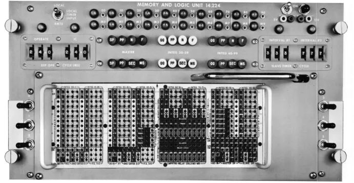
flexibility. The use of an auxiliary pre-patch panel allows the mode control program to be pre-patched and stored in the same manner as the analog computer program.
The Memory and Logic Control Unit (Figure 15) includes a central patching facility for controlling logical switch-ing functions, integrator modes, time-scales, repetitive and iterative operation of the computer with maximum
14
TABLE IV. 231R-V INTEGRATOR TIME SCALE PROGRAMMING
TIME CONSTANTS TIME CONSTANTS
PATCHING SEC BUTTON DEPRESSED MS BUTTON DEPRESSED
CONFIGURATION PP(TOP ROW)
N
DEPRESSED DEPRESS~
I
IC MS 0.1 N
~
0 0 0
10 SEC 10 SECES
F
I
OQ~
2
IC MS OJ
N
~
0
&~
10 SEC I SECES
0
3
IC MS OJ N
~
0 Gt.Ji)
~~
I10 SEC 0.1 SEC
0
AN Ie INPUT IS REQUIREC WHEN F PUSHBUTTON IS DEPRESSED
4
IC MS 0.1 N
~
~OO
ES F I10 SEC 10 SEC
Q£)
~AN IC INPUT IS REQUIRED WHEN MS PUSHBUTTON IS DEPRESSED
5
IC MS
OJ
&
~ ~&
~
10 SEC I SECAN IC INPUT IS REQUIRE[ WHEN MS PUSHBUTTON IS DEPRESSED
patch-bay with latching mechanism. As in the case of the Program Patching System, this latching mechanism also provides contact wiping action to maximize positive electrical connections. The Mode Logic Pre-Patch Panel is lettered and color-coded for ease in programming. Patching, terminations are arranged in a modular layout with provisions for simple inter-connection of integrator groups for multi-speed operation. Available patching accessories include bottle plugs, and normal and fan-out patch cords in a variety of lengths.
F
PP(TOP ROW)N
F
DEPRESSED DEPRESSED DEPRESSED DEPRESSED
I SEC 10 SEC 10 SEC I SEC
0.1 SEC 10 SEC I SEC 0.1 SEC
0.01 SEC 10 SEC 0.1 SEC 0.01 SEC
I SEC 0.0 I SEC 0.01 SEC 0.001 SEC
0.1 SEC 0.01 SEC 0.001 SEC 0.0001 SEC
REAL-TIME (RELAY) MODE CONTROL
Inputs to the Initial Condition and Hold Relays for each individual integrator are terminated in the inte-grator patching area of the Program Patch Panel. Con-trol of these relays may be accomplished in several ways.
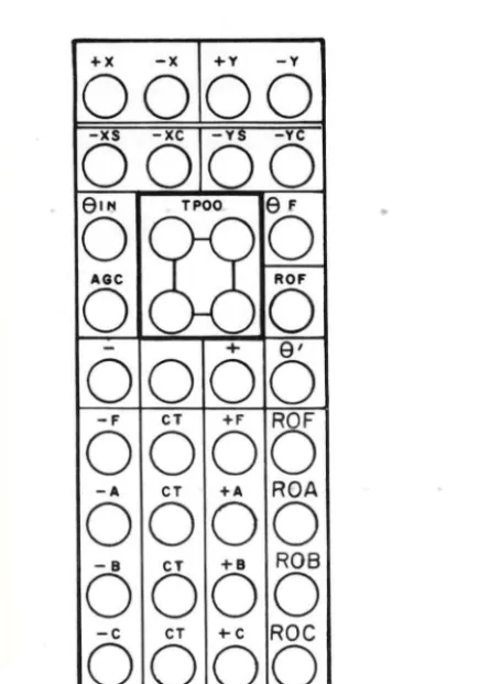
Figure 16. Mode Control Panel
the coils of the mode c~ntrol relays. are connected to
these busses by patching, it is possible, by
program-ming, to cause integrator groups to enter different modes
on energizing the same busses. The mode busses are
energized manually by means of pushbuttorts on the Mode
Control Panel (Figure 16) or automatically with a logic
level input from the Mode Logic Patch Panel. Lights
containted in the mode push buttons provide visual
indi-cation of the state of the mode busse s. This state is also communicated to the program bv means of Mode State
Lines which yield lever outputs at their Mode Logic
16
Patch Panel terminations. Slaving provisions permit relinquishing control of the mode busses to another 231R Console, a HYDAC Digital Operations System, or an Automatic Digital Input-Output System (ADIOS).
Mode relays may be controlled individually from the Mode Logic Patch Panel with Mode Relay Drivers. Each Mode Relay Driver accepts a logic level input and provides an output waveform capable of driving up to four mode control relays. Similar Mode Relay Drivers are also available with the HYDAC Digital Operations System.
HIGH-SPEED (ELECTRONIC) MODE CONTROL
The solid-state switches (Mode Control Gates) for both
the normal integrators and Analog Memory Units are
controlled by logic level inputs from the Mode Logic
Patch Panel. These inputs are terminated in the same
patching area (Figure 17) as the mode switch and
time-scale selection controls for each integrator. A unique
"reset" circuit permits maximum repetitive rates with the Mode Control Gates.
A number of summing amplifiers contained in the
com-puter may also be used as storage units. Conversion of
these amplifiers to Analog Memory Units, as well as
control of the associated solid-state mode switches, is
obtained through the Mode Logic Patch Panel. Although
an integrator with only an Initial Condition input may be used for storage, the storage summer adds the ability
to store a voltage sum without the use of additional
amplifiers. Individual Track-Hold networks with inputs
terminated on the Mode Logic Panel are also available for use with either summer or summer- integrator amplifiers.
MODE LOGIC PROGRAMMING
The auxiliary patch panel of the Mode Logic Program-ming System provides control flexibility for high-speed repetitive and iterative solution techniques. Control inputs and outputs are represented by binary ZERO and
ONE logic levels which may be inter-connected to establish the Mode Control Program. All components with logic level outputs provide complementary outputs for additional flexibility, while each output may be
patched to several points in the program with "fan-out"
patch cords. These logic levels may also be used for controlling external equipment by means of trunk lines
-or conversely, external logic levels, (e.g. from the
HYDAC Digital Operations System) may be trunked to
the Mode Logic Pre-Patch Panel. Communication be-tween the Mode Logic and Program Pre-Patch Panels is provided by inter-panel trunks and logic conversion
devices.
One of the primary purposes of Mode Control Logic
Pro-gramming is to offer the flexibility necessary for
high-speed repetitive operation of the computer. The Analog
Memory and Logic System includes several repetitIve drives for multi-speed repetitive operation. The basic timing reference, or "clock", for the system is a 10KC square-wave generator synchronized with a crystal oscillator. In slaving the Mode Control System of a 231R-V Control Console to that of another console, the 10KC Master Oscillators are synchronized. When the Series 1905 Display Unit is used in conjunction with the Analog Memory and Logic System, the Master Oscillator is synchronized to the timing oscillator in the Display Unit with the addition of the Display Unit to a system, supplemental repetitive drive frequencies of 2500, 500 and 250 cycles per second are available.
Repetitive operation with adjustable Initial Condition and Operate periods is obtained through the use of interval timers which are, in effect, event counters. The Mode Logic Patch Panel includes provisions for termin-ating two interval timers - referred to as the Master Timer (Figure 18) and Slave Timer (Figure 19). These three-decade counters count up to preset values for each of two intervals. At the end of one interval the counter
EXTERNAL REPETITIVE DRIVE
I
I
I
I .
.,
I
r---EXTERNAL
....
---
TRUNKSI MODE LOGIC COMPONENTS I
MASTER OSCILLATOR INTERVAL TIMERS
LOGIC GATES FUNCTION SWITCHES
I I I
,,-
I II I I I I I I I I I I I MODE TIME-SCALE RELAYS
I CONTROL
I GATES
I
r
-I
I
I
I
I r -I I I
-...,
L_ ....
A I 4
OP
B0 0 0
O-L
2 10 Ie AUT I
0
~&-
0
0,
3 CTR
B
I0
0
a
2
o
Figure 18 (left). Master Timer Patching Termination (MLPP) Figura 19 (right). Slave Timer Patching Termination (MLPP) is preset to the beginning of the second interval and again proceeds to count. At the end of each counting interval, the logic level output of the interval timer changes state - - the preset value or number of counts in each interval being determined by three-decade thumb-wheel switches on the Memory and Logic Control Unit. The counters may be reset to the beginning of either interval by means of pushbuttons on the control panel, or logic level inputs from the Mode Logic Patch Panel.
FUNCTION RELAYS t..
,.
ELECTRONIC loa
COMPARATORS'''"
DIGITAL / ANALOG
I ..
SWITCHES
.,
INTER-PANEL ---TRUNKS MODE RELAY DRIVERSJ
..
,
ANALOG PROGRAM PRE-PATCH PANEL.~ I
I I
•
MODE CONTROL RELAYS TIME- SCALE SELECTOR SYSTEML -- -
~L-
_ _ _ M_O_D_E_C_O_NT ___R~O_L_S_Y_S_T_E_M
_ _~
f
I•
REMOTE
- - - ANALOG SIGNAL MODE CONTROL
- - - - LOGIC SIGNAL
---RELAy CONTROL VbLTAGE
Inputs may be supplied to the interval timers by the 10KC Master Oscillator - or any other repetitive drive or logic level available at the Mode Logic Patch Panel. When an interval timer is driven by the Master OAcillator, each count is equal to one-tenth of a millisecond. The two counting intervals may, therefore, be adjusted from 0.1 to 99.9 milliseconds. In repetitive operation the two intervals are used to adjust the duration of the Initial Condition and Operate periods of the integrators. Slower repetitive rates may be obtained by cascading the interval timers. Events or conditions in the analog program detected by Electronic Comparators may also drive the timers.
To permit a greater degree of flexibility in mode control programming, the Analog Memory and Logic System in-cludes a number of General Purpose Logic Gates which may be used to enable or inhibit the operation of interval timers, comparators, mode control switches, etc. Since both the normal and complementary logic level outputs of these gates as well as other components in the system are available, the gates may be programmed to perform logical AND, NAND, OR, or NOR functions, or combined in pairs to function as flip-flops.
Complex Mode Control Programs may require the facility for normal operation of individual elements in the pro-gram for check-out, or to facilitate varying the configu-ration of the logic program. For this purpose, single-pole, double-throw function switches are included with the Memory and Logic Control Unit - - terminating at the Mode Logic Patch Panel. Write-on areas adjacent to the switches permit identification of their functions.
LOGIC CONVERSION
The success with which mode control programming may be used for the solution of complicated problems depends to a large extent on the ease with which the analog computer and mode control programs are able to com-municate with each other. The inter-face between the Mode Logic and Program Panels, in effect, d i vi des analog voltage signals from binary logic levels. To permit communication between two such dissimilar systems, logic-to-voltage and voltage-to-Iogic conversion must be possible. The Analog Memory and Logic System provides this communication in a number of ways. (Figure 20)
The occurrence of an event or existence of a particular condition in the analog program may be communicated to the mode control program by means of Electronic Comparators, which compare two voltage inputs from the analog program and generate proportionate logic level outputs; Latching inputs to the comparators from the Mode Logic Patch Panel establishes a capability to over-ride the voltage outputs with a logic level. Lights which indicate the state of the comparator output also contain push buttons with which the operator may manu-ally establish the comparator output during program check-out.
Logic levels may in tum act on the analog program when controlled by solid-state mode switches of the inte-grators or Analog Memory Units. Integrator mode relays are controlled from the logic program either by means of
18
the mode busses and Mode Bus Driver or with individual Mode Relay Drivers as described above.
Signal switching in the analog program may be accom-plished by either Digital-to-Analog Switches or Function Relays. The Digital-to-Analog Switch consists of a solid-state switch whose logic level control input termi-nates at the Mode Logic Patch Panel. These switches include precision input resistors and are used to switch voltages to the summing junction of an operational ampli-fier. When used in conjunction with an Electronic Com-parator, they form the electronic equivalent of a Relay Comparator for high-speed or repetitive operation use. The double-pole, double-throw Function Relays of the 231R-V embody transistor relay drivers which accept logi c level inputs. Relay Comparators are programmed by patching the output of an Electronic Comparator to these relay drivers.
Besides the logic conversion devices described above, an additional communication facility is supplied by inter-panel trunk lines - which are limited to logic voltage levels. An analog voltage input to these trunks may thus be used to drive elements of the mode control program; or conversely logic voltage levels may be introduced into the analog computer program. External trunks may be used to control external equipment or introduce external logic signals. In this manner, com-plex logic programs on the HYDAC Digital Operations System may supply inputs to the analog computer mode
control program.
TIME-SCALE PROGRAMMING
Precise computation by multi-speed techniques is readily accomplished using the 231R-V computer. With the Analog Memory and Logic System, anyone of six different time constants may be individually selected for each integrator by patch-panel programming or switch selection. The six corresponding time-scales range from 100 microseconds to 10 seconds; the 10 second time scale being available as an option. Time scales are grouped into high-speed and real time sets, each with SLOW, NORMAL and FAST modes of oper-ation, and are selected with proper patching of the Mode Logic Patch Panel. Capacitance is added or subtracted in parallel across the integrators--decreas-ing or increasintegrators--decreas-ing the speed of integration respec-tively.
Scale Selector of the Analog Memory and Logic System.
The Time-Scale Selector includes three groups of push-button switches which serve to activate control relays. These relays in turn select the mode" and time constant for each integrator by completing all required electrical connections through the Mode Logic Patch Panel. Each push -button group consists of two independently oper-ated rows of four buttons each. One set of push-buttons in each group is used to select either relay or electronic mode-switching for an associated group of integrators; another set IS used to select the inte-grator time constants.
Through appropriate combinations of selector and patch-ing arrangements, it is possible to operate one group of integrators in a program with one time-scale while another group of integrators is operated with a different time-scale. Moreover, with special patching, operating
(a) Summer· Integrator
(e) Summer
20
(d) Summer·lnverter
(e) Storage Summer
(f) Combination Track and Hold Unit
Figure 22. Amplifier Networks
COMPUT
I
NG
The computational section of a General-Purpose Analog Computing system is made up of a number of individual building blocks or components which perform the mathe-matical operations of addition, subtraction, multiplica
-tion, division, integra-tion, function genera-tion, etc.
Results are expressed in voltage form. These
comput-ing components may be di vided into five general cate
-gories: operational amplifiers, coefficient attenuators, multipliers, function generators, and switching devices. Within each of these categories are many possible variations in terms of speed, accuracy, and flexibility. Since these variations are reflected in the cost of the individual components, and ultimately in the cost of the computing system, a computer which satisfies the needs of both small and large-scale simulation labora
-tories must accommodate? wide variety of components. In addition to this, if the computer is to cope with increasing work load and problem complexity, it must
include provisions for expansion of both the quantity
and type of computing components.
The EAI 231R-V employs a modular expansion philoso-phy which makes it possible for each computer to be tailored to the immediate problem solving requirements of a particular customer, and yet permit future expan-sion to satisfy the broadest range of user requirements. A complete selection of electro-mechanical as well as all-electronic components makes it possible for the 231R-V to function both as a high-speed repetitive or iterative computer, and to satisfy requirements for real-time simulation.
Interchangeability of components, not only between computers- -but interchangeability of different types
of components as well, further extends the flexibility of the 231R- V. It permits the configuration of the
computer to be changed, or its capacity in creased,
depending on the requirements of individual programs. EAI's constant emphasis on progressive engineering includes a continuing program for the development of new computing components to either supplement or re
-place existing components. As a result, it is possible for a customer to up-date the 231R computer by adding or substituting new components as advancing tech-nology permits- -made possible by improvements in performance characteristics as well as in design and manufacturing techniques. This philosophy has made it possible for EAI computers to keep pace with the state-of-the-art- -avoiding the need for replacement or
addition of new equipments with minor programming and performance improvements.
OPERATIONAL AMPLIFIERS
By far, the most important component in an analog com-puting system is the High-Gain DC (Direct-Coupled)
Operational Amplifier. Nearly all linear and non-linear
operations occurring in the computer are accomplished by networks used in conjunction with the amplifier. The
utility of this device permits integration, summation,
inversion, multiplication, function generation, c
oordi-COMPONENTS
nate transformation, plus many other computing func
-tions. In fact, in defining computing capability, pres
-ent-day owners of analog equipment cite the quantity
of amplifiers in their installations or applications as a
figure of merit. Hence, "a two-hundred amplifier system" expresses the problem-solving capability for that amount of equipment.
In almost all situations it is the amplifier's character
-istics that determine the computer program accuracy and dependability of performance. Specifications such as high output current, low output impedance, high-gain, wide bandwidth, hi gh velocity limi t, low-drift, low noise and high stability are essential requirements for good computational results. Just as important is the variation of these characteristics with time and environ
-mental conditions. Continuous operation of the ampli
-fiers in a computer installation necessarily demands long-term reliability with a minimum down-time for maintenance considerations.
To fulfill all of these criteria, EAI provides the Model
6.217 Dual DC Operational Amplifier (Figure 21) in
the 231R-V Analog Computer. Years of experience in the development and manufacture of analog computing equipment has fostered improvements over many suc
-cessive generations of operational amplifiers to yield
the advanced field-proven design of the Model 6.217. This amplifier's output current capability eliminates
the need for using multiple-amplifier circuits to drive large loads. A low drift feature, when performing
inte-gration, allows long-term open loop computation. The design for high natural cut-off frequencies within the
amplifier permits stable operation over a wide range of
feedback impedances, assuring proper performance in special function generating circuits. Low hum, noise
and cross talk, coupled with the amplifier's excellent
dynamic characteristics, enable the computer to per
-form the many repetiti ve and iterative calculations re-quired by modern computing technology.
Consistent employment of the Model 6.217 Amplifier
with all 231R-V equipment assures uniform computing
quality throughout the system, and provides complete
interchangeability among amplifier chassis. Each
Model 6.217, containing two amplifiers mounted on
teflon printed-circuit cards, is a plug-in unit which is
installed and removed from the front of all computing
I C PS
0 0
COIL COIL
00
BUS H
00
f
05
00
G C
00
05
Q§00
SJ
05
0 0
10 HI
0 0
10
P05
0 0
10
105
0 0
I
0
0
1 ~
0 0
I
10
0
Figure 23. Summer-Integrator Patching Termination (Program Patch Panel)
cabinets offering easy accessibility for servicing. Located on the front panel of each chassis are the individual balancing controls. Overload indication is
at the Control Console.
The amphfier design incorporates a dynamic balancing
circuit to minimize inherent drift of the direct-coupled
amplifier stages. This balancing is accomplished with.
an A.C. stabilizer section, which pre-amplifies the
D.C. and low-frequency components of an input signal
before they reach the D.C. amplifier. As a result of the additional gain of the stabilizer, the amplifier summing junction is maintained at essentially zero,
thereby compensating for any drift in the amplifier.
Other design features include an EAI-patented circuit
for rapid recovery from overload conditions, and special
decoupling networks to eliminate power source c r 0 s s
talk.
AMPLIFIER NETWORKS
Amplifier performance characteristics are a major con-sideration in the achievement of proper computing
22
accuracles. Equally as important, however, are the
various input and feedback networks used in
conjunc-tion with the amplifiers to perform linear and non-linear operations; e. g., sign inversion, summation, integration, function generation, etc. It follows that these networks must be of such a design as to ma
in-tain the high standard of operation established by the
computing amplifiers.
To meet these requirements, all critical network ele
-ments of the 231R- V are housed in the
temperature-stabilIzed oven of the Control Console. Precision resistors, capacitorS, diodes and switching circuits are packaged in fully-shielded metal enclosures which
plug directly into banana pin receptacles mounted on
the rear of the patch bay. These network cans
physi-cally mate with corresponding shields also mounted on the patch bay, offering complete protection against network cross-coupling effects. In addition, shielded
output wiring and coaxial cable inputs to amplifier
grids assure low noise operation with minimum inter
-action. For similar reasons, integrating capacitors are located in a separately enclosed section of the oven
to maintain a restricted-temperature environment. This
location also permits easy accessibility for mainte-nance adjustments.
Of major concern in the various types of oven networks is the quality of the precision input and feedback
resistors. To meet the stringent computing requirements of problem applications, these elements are specially manufactured for EAI to yield essential low tolerance
and long-term stability characteristics. Non-inductive, wire-wound resistors, thermally aged and stabilized
before EAI receives them, are used throughout. On ce
mounted in a network can, frequency-compensating
capacitors are added to each resistor and adjusted to produce the best dynamic performance possible. The amplifier networks (Figure 22) may be grouped
into three main categories, depending on their function.
They are the Summer-Integrator, the Summer and the Analog Memory Unit. Each of these includes precision network components and switching circuitry necessary to permit their use with an operational amplifier as a
high-accuracy computing component having maximum programming flexibility.