DEC-lS-YWZA-DN3
UPDATE #3 TO PDP-IS
UTILITY PROGRAMS MANUAL
SGEN
SYSTEM GENERATOR
UTILITY PROGRAM
NOTE
THIS MANUAL IS A COMPLETE REPLACEMENT FOR THE SGEN
SECTION OF THE PDP-IS UTILITY PROGRAMS MANUAL
PRINTED OCTOBER 1969.
PRINTED SEPTEMBER
1970
COPYRIGHT (C)
1970
BY DIGITAL EQUIPMENT CORPORATION
THE MATERIAL IN THIS MANUAL IS FOR INFORMATIONAL
PURPOSES AND IS SUBJECT TO CHANGE WITHOUT NOTICE.
THE FOLLOWING ARE TRADEMARKS OF DIGITAL EQUIPMENT CORPORATION,
MAYNARD, MASSACHUSETTS:
DEC
FLIP CHIP
DIGITAL
PDP
FOCAL
PREFACE
The system Generator (SGEN) program described in this manual may be used only with the VSA or later versions of the Advanced Monitor Soft-ware System for PDP-lS/20/30/40 configurations.
To New Users
The SGEN program provides the user with the means to rapidly tailor the general-purpose ADVANCED software system provided by Digital into a system optimized for his particular needs.
Prerequisite
In the preparation of this manual, i t was assumed that the reader is familiar with the Advanced Software System; e.g., its Monitor and Utility programs, etc.
PDP-IS/20/30/40 ADVANCED MONITOR SOFTWARE SYSTEM MANUAL, DEC-IS-MR2B-D
This manual provides descriptions of system programs including discus-sions of: languages, utilities and application, operation, core
organization, and input/output operations within the Monitor environ-ment.
PDP-IS UTILITY PROGRAMS MANUAL, DEC-IS-YWZB-D
The PDP-IS Utility Programs manual is comprised of a set of individual manuals, each of which describes the operation and use of a PDP-IS Utility Program. The manuals which make up the Utility Programs set are listed in the following Application Guide. In addition, the guide also indicates the order number of each manual and the specific PDP-IS Monitor Software Systems in which the program described may be used.
The Utility Manuals may be ordered either individually, by using the title and order number given with each manual or as a set by referenc-ing "PDP-IS Utility Programs Manual, DEC-15-YWZB-D".
APPLICATION GUIDE
PDP-1S Utility Program Manuals and the Application of Each
Manual Applies to Monitor:
Title Order Number DOS ADV B/F BASIC I/O
(DEC-1S-YWZB- )
DDT DNl I I I I
Utility Program
CHAIN & EXECUTE DN2 I I I I
Utility Program
SGEN DN3 I
ADVANCED Monitor
MTDUMP DN4 j I I
Utility Program
PATCH DNS I j I
Utility Program
EDIT DN6 I I I I
Utility Program
UPDATE DN7 I I I
utility Program
LINKING LOADER DNB I I I I
PIP DN9 I I I
ADVANCED Monitor
PUNCH DN10 I
Utility Program
SRCCOM DNll I I I
Utility Program
SGEN DN12 I
DOS Monitor
PIP DN13 I
DOS Monitor
Disk SAVE/RESTORE DN14 I I I
To Users Familiar with Previous Versions of SGEN
This new SGEN program provides the user with greater power and flexi-bility in the generation of new systems and, as a major new feature, permits the straightforward and rapid modification of existing systems. In modifying an existing system, the user may alter:
(1) API and Teletype usage,
(2) system I/O devices and device handlers,
(3) the contents and order of the system Skip Chain,
and
(4) the system .OAT slot assignments.
The new features offered by SGEN in the generation of new systems in-clude:
1. The complete deletion of all unwanted device handlers or system programs from new systems.
2. The ability to add user programs to the new system as system programs.
3. The optional addition of a system
to
core dump area. 4. The ability to re-order system programs and to specify1.1 1.2 1.2.1 1. 2.2 1. 2.3 1.3 1. 3.1 1.3.1.1 1.3.1.2 1.3.1.3 2.1 2.1.1 2.1. 2 2.1. 3 2.2 2.2.1 2.2.2 2.3 3.1 ·3.1.1 3.2 3.2.1 3.2.1.1 3.2.2 3.2.2.1 3.2.3 3.2.4 3.2.5 3.2.6 3.2.7 3.2.7.1 3.2.8 3.2.8.1 3.2.8.2 3.2.8.3 CONTENTS
SECTION 1
INTRODUCTION
System Generator
SGEN, Basic Units and Features SGEN Program Unit
.SGEN2 Program unit .SGEN3 Program Unit SGEN Operations
Pre-operational Considerations New System Size
Calculating tQ Area
MACROI and F41
SECTION 2
SYSTEM GENERATION STEP-BY-STEP PROCEDURE
Contents
Procedure Notes and References Procedure Headings
Conventions Used in Procedure
Preparatory Device/.DAT Slot Assignments New Systems
Updating Old Systems Step-by-Step Procedure
SECTION 3
SGEN OPERATIONS, SPECIAL CONSIDERATIONS
Contents
Single Vs. Multi-System Users Selection of Responses
CORE SIZE (8,12,16,20,24,28, OR 32K) [XX]
4K ON/OFF Switch API?
API ON/OFF Switch
tQ AREA? ( )
EAE? ( )
DELETE DISCARDED HANDLERS FROM .LIBR?
MAX. SYSTEM BLOCK # [1~77]
33TTY? ( )
33 TTY ON/OFF Switch
Deletion/Addition of I/O Devices and Handlers DEV NAME
NEW HANDLERS SKIP lOTS
3.2·9
3.2.10
B. DISPLAY SKIP CHAIN?
CHANGE SKIP CHAIN ORDER?
3.2.10.1 Use of ALTMODE in Re-ordering New System
Tables
3.2.11
3.2.12
3.2.13
C. DISPLAY .DAT SLOTS?
ALTER .DAT SLOTS:
D. CHANGE SYS PROG?
3.2.14.1 Adding F41 and MACROI Programs to an
BK
System
3.2.15
ADD SYS PROG.?
3.2.15.1 PROG. NAME (6 OR LESS ALPHANUMERICS)
3.2.15.2
#
OF DEVICE BLOCKS
3.2.15.3 .DAT SLOTS (-15 to 10 OR ALL):.
3.2.16
3.2.17
3.2.1B
3.3
E. DISPLAY PROG ORDER
DELETE RELOCATABLE FILES?
CHANGE PROG. ORDER
Optimal Loading of System Programs
Appendix A
Appendix B
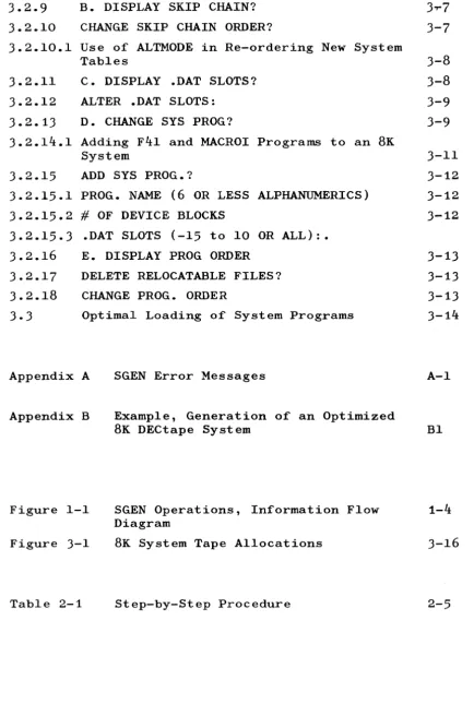
Figure 1-1
Figure 3-1
Table 2-1
SGEN Error Messages
Example, Generation of an Optimized
BK
DECtape System
SGEN Operations, Information Flow
Diagram
BK
System Tape Allocations
Step-by-Step Procedure
[image:10.602.89.523.38.694.2]SECTION 1 INTRODUCTION 1.1 SYSTEM GENERATOR
A general-purpose ADVANCED Monitor software system is supplied with each PDP-IS configuration which includes some form of mass storage
(e.g., DECtape or DECdisk) and DECtape or magnetic tape for backup. A system Generator program (SGEN), provided as part of the general-purpose package, enables the user to tailor and add to the supplied software in order to develop a resident software system unique to the installation or to his specific needs.
The general-purpose software is normally supplied to the PDP-1S user on a DECtape. This general-purpose DECtape contains all of the standard PDP-1S/20 System Programs, Utility Programs, and I/O device Handlers supplied and supported by DEC; i t should never be modified, as permitted by SGEN, but should be maintained as a master reference tape.
1.2 SGEN, BASIC UNITS AND FEATURES
SGEN provides the user with two basic capabilities: 1) i t may be used to modify an existing software
system (see 1.2.1),
2) i t may be used to generate a new (specialized) system from either the master general-purpose system or a previously generated system (see 1.2.2 and 1.2.3).
The SGEN program is divided into three units entitled SGEN, .SGEN2, and .SGEN3. During system generation the three program units are loaded into core in sequence with each succeeding unit overlaying the resident unit. Only the first unit, SGEN, is required in the modification of an existing software system; all three units are required in the generation of a new software system.
1.2.1 SGEN Program Unit
3) the alteration of .DAT slot assignments using standard monitor assign commands. The modification of an existing software system is terminated on the completion of this program unit.
1.2.2 .SGEN2 Program Unit
In the development of a new software system, unit .SGEN2 is called into core by and overlays the SGEN unit on completion of its opera-tions. The capabilities offered by .SGEN2 are related to SYS file l programs, the system control Q (10) area, the system SYSBLK area and the system monitor commands (in SKPBLK). Program unit .SGEN2 allows the user to:
1) delete the ~ area from the new system, 2) delete SYS file system programs,
3) set up file storage and control areas in the new system for the addition of new SYS file programs to the system.
4) permit the re-ordering of the location of the SYS files on the new system medium.
The system directory of the new system to be generated is automatic-ally updated during .SGEN2 operations to include the names and starting block numbers of all SYS files to be included in the new system.
1.2.3 .SGEN3 Program Unit
The .SGEN3 program unit is called into core by and overlays unit .SGEN2 on completion of its operations. The capabilities provided the user by the .SGEN3 unit include:
1) the ability to delete from the system library (.LIBR BIN) the program units of user-deleted handlers (.SGEN2 operation);
2) the ability to update the desired versions of the Object Time System (OTS) REAL and INTEGER software routines (EAE or non-EAE) into the new system library;
3) the ability to transfer selectively the reloca-table files contained by the Old System input source into the new system.
During the operations of this program unit, version C of the system device handler is automatically relocated and placed into the cor-rect area of the new system. On completion of the .SGEN3 program unit, the nonresident monitor is called back into core.
1.3 SGEN OPERATIONS
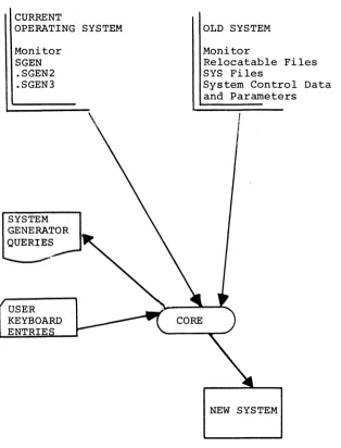
In order to develop a new system (see Figure 1-1) the System
Genera-tor program requires:
1) a "current" operating system from which the monitor
and the required program units of the SGEN program may be loaded;
2) an "old System" input source from which the "current" system can obtain inputs required to construct the new system;
3) a "new system" output device on which to build the desired system.
In many cases, both the "current" and the "Old" systems may be the
same system; for example, when a new system is being generated
from the Master DECtape supplied by Digital, all required inputs may
be obtained from the single master source.
The operations of the System Generator are carried out on an
inter-active program/user basis via program printouts and user keyboard
inputs. A step-by-step procedure illustrating the program printouts
and required user responses for the System Generator operations is
given in Section 2.
System generation may be carried out from DECtape to DECtape,
DEC-tape to DECdisk, DECdisk unit to DECdisk unit, and DECdisk unit to
DECtape.
1.3.1 Pre-Operational Considerations
Careful planning is necessary to ensure that the most efficient
system will be developed for the user's particular needs. Some
items to be considered in the pre-operational planning of a new
system generation are described in the following paragraphs.
1.3.1.1 New System Size
--The size of the system to be developed must be calculated to
determine if i t will fit the selected output device. The maximum
length, in 400S-word blocks, for systems on DECtape or DECdisk
are:
1) DECtape
2) DECdisk
1100 S blocks
1000S blocks
(~ - 1~77S)
CURRENT
OPERATING SYSTEM Monitor
SGEN .SGEN2 .SGEN3
SYSTEM GENERATOR QUERIES
OLD SYSTEM Monitor
Relocatable Files SYS Files
System Control Data and Parameters
[image:14.599.146.461.92.505.2]NEW SYSTEM
One procedure which could be used to determine the number of free system blocks available for adding programs would be to:
1. Call PIP and obtain a directory listing using the PIP "L" command. This will give the number of free system blocks, the number of SYS file blocks, and the name and number of blocks occupied by each relocatable file.
2. Call PATCH and obtain the size of each SYS file through the use of the PATCH "NB" command. Using the NB command (e.g., [SYS file name] NB ) for each SYS file named in the monitor directory will give the size in blocks of the system area allotted to each SYS file.
If MACROI and F4I programs are present on the "Old System" and the new system is to have a core size larger than SK, an additional 100S system blocks will be freed by the automatic deletion of
these programs (40 S blocks apiece).
If a system without a tQ area is used as the Old System, the size of the tQ area for the new system, if desired, must be subtracted from the number of free blocks in. the old system in order to deter-mine the number of blocks available for additional programs (e.g., Master tapes distributed by DIGITAL do not contain tQ areas). 1.3.1.2 CALCULATING tQ AREA
The System Generator will reserve 20S blocks for each 4K of
core specified by the user as the tQ area. A smaller 1Q area than core size would result in the loss or clobbering of system files if a tQ~ command is given. A system with no tQ area will not allow a tQ~ command to be executed, but will wait for another unit number.
NOTE
The deletion of the tQ area from a system prohibits the use of the ~~ command but does not remove the
to
function from the system. Core images may be dumped onto any non-zero (non-system) device by the use of the tQ command (e.g., tQ~ cannot be used, however, 1Ql can).1.3.1.3 MACROI AND F4I
During the generation of systems larger than 8K, MACROI and F4I are automatically deleted from the new system. The new system, however, will contain the control data associated with these programs.
SECTION 2
SYSTEM GENERATION, STEP-BY-STEP PROCEDURE 2.1 CONTENTS
A complete step-by-step system generation procedure is presented in this Section. The procedure itemizes and describes each possible operation. Teletype printouts of the System Generator outputs and user inputs are also illustrated where applicable.
2.1.1 Procedure Notes and References
Where necessary, examples and notes (both directive and explanatory) are given in the procedure itself. Paragraph references are
given in the procedure for supplementary data contained by Section 3 "SGEN OPERATIONS, SPECIAL CONSIDERATIONS".
2.1.2 Procedure Headings
The column headings used in the tabular procedure format and the meaning of each are as follows:
1. ITEM - reference number.
2. PROCEDURE - a description of each SGEN Program printout made and the required user response is given in this column. 3. PRINTOUT - a typed representation of the actual
Teletype printout of each output is given in this column. Normally, printouts are printed on a single line: however, manual page format space restrictions require the longer messages to be illustrated on two or more lines.
4. REFERENCE - paragraph numbers which identify detailed descriptive data, normally concerning the selection of a re-sponse, are presented in this column. 2.1.3 Conventions Used in Procedure
The following conventions are used throughout the SGEN Program pro-cedure:
a. The? symbol may be followed by paren-theses containing the response (Y or N) given in the generation of the old sys-tem. For example, the printout
7 CHANNEL MAGTAPE (Y)
indicates that the old system response had been Y (yes).
b. In BATCH mode, all Y or N user responses MUST be terminated by a
.J+
(CRLF) entry.2. In the SGEN Program, procedures incorporating informa-tion from an old system and which require a response different from Y or N may be followed by a set of brackets [ ] containing the old system response. (The bracketed symbols represent the response given during the generation of the old system.)
For example, the printout
MAX. SYSTEM BLOCK # [1~77]
requests the entry of the number of the system block which is to contain the last information to be stored on the tape; the number [1~77] indicates that the old system response had been number 1~77.
3. SGEN Program queries which require or provide for a multiresponse are formatted as follows:
( a)
(b)
FORMAT
Message terminated in a colon is printed
CR,LF is performed and an angle bracket is printed
EXAMPLE NEW HANDLERS:
>
The user responds by entering the needed responses, one response per line (> is echoedlat start of each line until all entries are made. The response series is terminated by entering (after > ) the word DONE or, in a non-Batch mode, a single) .
For example:
NEW HANDLERS: >DRA
>DRB
>DONE (or.))
4. An ALT MODE response is echoed by the Teletype as a dollar sign $.
NOTE: ALT MODE responses are not permitted in Batch mode.
5. SGEN Program operations are divided into five sec-tions identified by the letters A., B., C., D., and E., which appear as the first letter in the printout which introduces the section. A control P (tP) command issued at any time within any sec-tion of SGEN returns the procedure to the first statement of that section. This sectionalization of the SGEN programs with respect to the user of the
tP command enables the user to correct any mistakes made within a section rather than requiring the entire procedure to be repeated. The ITEMS of the following procedure at which the SGEN program sec-tions are introduced are:
Section A. ITEM 12 Section B. ITEM 23 Section C. ITEM 26 Section D. ITEM 27 Section E. ITEM 28
6. Printout operations may be terminated line by line by the entry of a control U (tU); the printout will be terminated on the line and character printed at the time of entry, and the next line will be output
(if one exists). Individual characters may be deleted (erased) from an input by using the Rubout (echoes , symbol for each character deleted).
7. The representative printouts illustrated under the column "PRINTOUT" use the following conventions: a) Required user inputs are indicated as
under-lined areas. For example:
NEW SYSTEM? (The underlined area indicates that the user response should be entered at that point)
b) Unknown numeric values are indicated by the letters "XX". For example:
tQ AREA SIZE [XX] ~(user response)
1
(unknown numeric value)2.2 PREPARATORY DEVICE/.DAT SLOT ASSIGNMENTS
2.2.1 New Systems
The generation of new systems requires the following assignments: -14
-15
Old system
New system
The old system does not have to be the current system; however, both systems must be V5A or later tems (current system means the sys-tem being used) .
The device on which the new system is to be generated must be assigned to this .DAT slot. The contents of this device medium are ignored and overwritten.
In 8K, when generating a new system onto a device different from the old system device, the Al handler should be assigned the old system device, and the El handler assigned for the new device. The handlers must be assigned in this manner since two device A handlers and the SGEN program cannot fit into 8K of core.
EXAMPLE: The following is an example of the device handler and .DAT slot assignments which are made in a typical DECtape system SGEN operation.
Device Old System New System
Handler and unit DTAI
DTA2
2.2.2 Updating Old Systems
.DAT slot -14 -15
In updating old systems, the device assigned to .DAT slot -15 is ignored and the system contained by the device assigned to .DAT-14 is modified. In this type of operation:
1) .DTA-15 should be assigned to same device as .DAT-14
2) When updating, the device on -14 must be WRITE ENABLED.
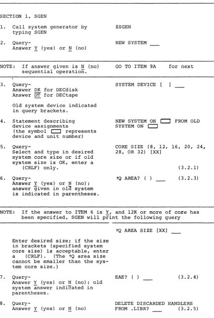
2.3 STEP-BY-STEP PROCEDURE
The operations which may occur in the use of the ADVANCED Monitor System Generator are given in the following table.
1
Table 2-1 Step-by-Step Procedure
ITEM PROCEDURE
SECTION 1, SGEN
1. Call system generator by typing SGEN
2.
Query-Answer Y (yes) or N (no)
NOTE: If answer given is N (no) sequential operation. 3.
Query-Answer DK for DECdisk Answer DT for DECtape
Old system device indicated in query brackets.
4. Statement describing device assignments
(the symbol c:::J represents device and unit number) 5.
Query-Select and type in desired
system core size or if old system size is OK, enter a
(CRLF) only. 6.
Query-Answer Y (yes) or N (no); answer given in ola system
is indicated in parentheses.
PRINTOUT REFERENCE ()
$SGEN NEW SYSTEM
GO TO ITEM 9A for next
SYSTEM DEVICE [
NEW SYSTEM ON
c:::r
FROM OLD SYSTEM ON c:::JCORE SIZE (8, 12, 16, 20, 24, 28, OR 32) [XX]
to
AREA? ( )(3.2.1) (3.2.3)
NOTE: If the answer to ITEM 6 is Y, and 12K or more of core has been specified, SGEN will print the following query
7.
8.
Enter desired size; if the size
in brackets (specified system
core size) is acceptable, enter a (CRLF) . (The tQ area size cannot be smaller than the sys-tem core size.)
Query-Answer Y (yes) or N (no) ; old system answer indicated in parentheses.
Query-Answer Y (yes) or N (no)
2-5
tQ AREA SIZE [XX]
EAE? ( ) (3.2.4)
[image:21.599.89.515.62.694.2]ITEM PROCEDURE PRINTOUT REFERENCE ( ) 9.
Query-Enter octal number of block which is to be the last
ac-cessible block in the system. The number within brackets represents the last block in the old system
MAX. SYSTEM BLOCK
*
[1~77](3.2.6)
NOTE: If the SGEN program is to be used to modify an old system (answer to Item 2 is Y), i t will print out the following query at this point:
10. II. 12.
MODIFY SYSTEM ON XXX where XXX represents the name
and unit number identification (e.g., DKl) of the device con-taining the old system.
If the device identification given is not correct, an error was made in preparatory .DAT slot assignments.
Query- API? ( ) (3.2.2)
Answer Y or N
Query- 33TTY? ( ) (3.2.7)
Answer Y or N
Query- A. ALTER I/O DEVICES OR
Answer Y or N HANDLERS? (3.2.8)
NOTE: a. If an N answer is given for ITEM 12, the procedure goes to ITEM 23 for the next sequential operation.
b. If a Y answer is given for ITEM 12, the operations de-scribed in ITEMS 13 through 22 are performed.
THE ENTRY OF tP AT ANY POINT IN THESE OPERATIONS RETURNS SGEN TO ITEM 12.
13. Statement, TO BE KEPT: (3.2.8)
NOTE: The statement of ITEM 13 introduces a series of individual multi-line query groups (1 per standard device) which established the devices and device handlers to be kept in the system or added to the system. The following is an example of a device query group (paper tape punch) and instructions as to how the queries are to be handled: Instruction
a. Answer Y to keep punch, N to drop punch and skip to next query group
ITEM PROCEDURE PRINTOUT REFERENCE b. Handler Version A. Answer Y
to keep, ~ to drop.
c. Version B, Y to keep, N to drop.
d. Version C, Y to keep, N to drop.
e. Go-Ahead symbol, type in mnemonic of any PP handler to be added. If no more entries, type in DONE or CRLF ( ) ) . Refer to~.8 for a detailed description of how to add handlers here.
f. SGEN prints the skip lOT as-sociated with the device for user convenience.
PRA? PRB?
PRC?
>
PSF=7~~2~1
NOTE: ITEMS 14 through 21 illustrate the standard query groups normally presented to the user.
14. Paper Tape Reader Query group
15. Paper Tape Punch Query group
16. DECtape Query group
NOTE: If DECtape is the selected system device, its printout will be formatted as shown
for the DECdisk in this pro-cedure (ITEM 17) .
PR? PRA?--PRB? RSF=7~~1~1 PP? PPA?" PPB?--
PPC?>
-PSF=7~~2~1 DT? DTA?" DTB?-- DTC?-- DTD?--DTE? DTF? >---DTDF=7~76~1 DTEF=7~7561 ( )
17. DECdisk Query group DK IS SYSTEM DEVICE AND DKC IS SYSTEM HAND NOTE: Group format shown here would
occur if DK was selected sys-tem device, otherwise its for-mat would be the same as shown in ITEM 16.
ITEM PROCEDURE PRINTOUT REFERENCE
18. Magnetic Tape MT?
MTA~
MTC?
--MTF?
>
MTSF=7~7341
19. Line Printer LP?
LPA~
>
LSDF=7~65~1
20. Card Reader CD?
CDB-:r-->
RCSF=7~67~1
RCSD=7~6721
2l. VP5A Display VP?
VPA~
>
SDDF=7~~521
22. Query~ ADD NEW DEVICES (3.2.8)
NOTE: The query of ITEM 22 gives the user an opportunity to include any additional I/O devices and their handlers in the system being developed.
A N (no) answer to the query causes SGEN to go to the opera-tion presented in ITEM 23.
A Y (yes) answer to the query causes SGEN to enter the series of-operations given in ITEMS 22a through 22.
DETAILED INSTRUCTIONS ARE NOT GIVEN FOR ITEMS 22a THROUGH 22b; REFER TO REFERENCES PARAGRAPH(S) FOR INFORMATION. 22a.
Query-Enter a unique 2-letter name. 22b. Query and go-ahead symbol.
Enter handler mnemonics - one per line. Terminate list by entering DONE after symbol.
22c. Query and go-ahead symbol. Enter needed skip lOT's for device named in Item 22a. lOT format is: SKIP
MNEMONIC
=
6-digit octal number representing lOT in-struction.
DEV NAME (3.2.8.1) NEW HANDLERS :
>-- (3.2.8.2)
>--->DONE (or) ) SKIP lOTS:
> (3.2.8.3)
> DONE (or )
ITEM PROCEDURE PRINTOUT REFERENCE ()
22d. Query- ADD I/O DEVICES? (3.2.8)
NOTE: The query of 22d. enables the user either to repeat ITEMS 22a through 22c. for the entry of another device, its handlers and its skip lOT's or to exit from this operation and go to ITEM 23.
Answer Y to repeat cycle
N
to exit to ITEM 23. 23.Query-A Y answer causes the program to-print out the system skip chain as derived from old sys-tem tape.
An N answer advances the pro-cedure to ITEM 24.
B. DISPLAY SKIP CHAIN?
(3~9)
NOTE: It is advisable to obtain a printout of the skip chain to ensure that all of the desired skip lOT's and only those, are included in the new system. (Refer to paragraph 3.2.9 for more detailed information concerning this operation.) The following is an example of a Skip Chain printout, the function for each (not printed during System Generation) is also given:
*a} Power Fail
b} DECtape Done Flag c} DECdisk Done
d} Mag. Tape Done or Error e} Store, Display Done f} Card Column Ready g} Card Done
h} Line Printer Done *i} Clock Done
j} Reader Done k} Punch Done
*l} Keyboard Done (TTA) *m} Teleprinter Done (TTA)
n} DECtape Error Flag
*o} Non-Existent Memory Ref. *p} Memory Protect Violation *q} Memory Parity Error
SPFAL DTDF DSSF MTSF SDDF RCSF RCSD LSDF CLSF RSF PSF KSF TSF DTEF MPSNE MPSK SPE
*These skips are associated with permanent resident moni-tor handlers and functions, they will always appear in the Skip Chain unless specifically deleted.
24.
Query-Answer Y or N
CHANGE SKIP CHAIN ORDER? (3.2.l0) NOTE: An N answer to ITEM 24 advances the procedure to ITEM 25 for
the-next sequential operation.
ITEM PROCEDURE
24a. Statement and go-ahead symbol. In BATCH mode the user must type in -one per line- each SKIP lOT. In Non-BATCH mode the user may enter an ALT MODE command ($) and
the first unused SKIP from the old order is automatically supplied on that line. Terminate list by entering DONE. 25. Special Device questions.
The user may have certain optional devices for which additional information is needed. The following ITEMS detail the questions asked in these cases:
25a. 339 Display (1)
Query-Answer Y if 339 table
is to
be
included in the monitor.(2)
Query-Answer Y if a 339 push-down list is to be in-cluded in the monitor. 25b. Magnetic Tape:
The assumption will be 7 channel if Y is typed and 9 channel i f N is typed. 25c. Line Printer
Query-26.
Answer with the maximum num-ber of characters which may be printed on one line. The number should be one speci-fied in the query.
Query-Answer Y or N
PRINTOUT REFERENCE ()
TYPE NAMES IN NEW ORDER ($ CAUSES FIRST UNUSED SKIP FROM OLD ORDER TO BE SUPPLIED):
>
->DONE (or)
(3.2.10.1)
339 LOAD DEFAULT LOAD? (
LOAD VC38 TABLE? ( )
7 CHANNEL MAGTAPE? ( )
LINE PRINTER LINE SIZE?
(8~, 12~, OR 132) [XX]
C. DISPLAY .DAT SLOTS?
NOTE: An N answer to ITEM 26 advances the procedure to ITEM 26a for the-next sequential operation.
A Y answer to ITEM 26 causes a printout of an ordered list of the current new system .DAT slot assignments and will initiate ITEM 26a.
ITEM PROCEDURE
-15 DKA2 -14 DKAI -13 DKA2 -12 TTA~
-11 DKAI
-l~ TTA~
- 6 DKA2 - 5 NONE - 4 DKA2 - 1 DKA~
1 DKA~
2 DKAI 3 DKA2 4 TTA~
5 PRAf.)'
6 PPA~
7 DTAI
l~ VPA~
PRINTOUT REFERENCE (
26a. Query and go-ahead symbol
ALTER .DAT SLOTS:
>
(3.2.12) Answer by entering
a reassignment com-mand until all changes are made.
Terminate operation by entering DONE Example:
>A DTBl -13/DT2 If.J',-6/DT 3 >DONE
>DONE (or ~)
NOTE: If the procedure was intended for the modification of an Old System (ITEM 2 answered N) the operation would have been com-pleted by the termination of ITEM 26a. The completion of the procedure is indicated by the following printout:
27.
Query-SGEN COMPLETE MONITOR
$
Answer Y or N
D. CHANGE SYS PROG.?
13."2.13)
NOTE: The query of ITEM 27 permits the user to initiate a cycle of operations during which System Programs may be deleted or added to the group to be installed in the new system.
A Y answer to ITEM 27 initiates the operations presented in ITEMS 27a and 27b. An N answer to ITEM 27 causes the SGEN program to proceed to ITEM 28.
27a. Statement followed by a series of one-per-line queries.
Answer queries: Y to keep program,
N to delete program.
TO BE KEPT: DTCOPY? SRCCOM?--F4I? EDIT~ EDITVP? MACRO? (3.2.14)
TYPICAL EXAMPLE
ITEM PROCEDURE PRINTOUT PIP? F4? SGEN? DUMP?--UPDATE? MACROI?--CHAIN?
PATCH?--REFERENCE ( )
NOTE: If an 8K new system is being generated and the Old System does
not contain F4I or MACROI, the following statement and queries are made to enable the user to add these files to the new sys-tem.
27b.
Query-TO BE ADDED: F4I?
MACROI?
ADD SYS PROG.?
(3.2.14)
(3.2.15)
NOTE: A Y answer to ITEM 27b starts a cycle of queries (ITEMS 27c,
d and e) designed to obtain the name, size and .DAT slot
as-signments of each program to be added. .SGEN returns to ITEM
27b and repeats the cycle until an N answer is obtained.
An N answer advances the SGEN program to ITEM 28.
27c.
Query-Answer by entering desired name.
27d.
Query-Answer by entering in oc-tal the number of blocks required to store pro-gram.
27e. Query and go-ahead
symbol.
Answer by entering desired .DAT slot assignments; termin-ate List by entering DONE.
28.
Query-Answer:
Y if a multi-line print-out of system program names as they appear in the system is wanted. N if printout is not wanted.
PROG. NAME (6 OR LESS ALPHA-NUMERIC)
(3.2.15.1)
# OF DEVICE BLOCKS [ ]
(3.2.15.2)
.DAT SLOTS (-15 TO 10 OR ALL) :
>
->DONE (OR
.J)
E. DISPLAY PROG. ORDER? (3.2.16)
NOTE: An example of a System Pr6gram Order printout obtained if ITEM
ITEM PROCEDURE EDIT EDITVP PIP MACRO CHAIN F4 DUMP DTCOPY PATCH UPDATE SRCCOM SGEN 29.
Query-Answer:
N if no files are to be dropped; the procedure advances to ITEM 30. Y if changes are to be made; ITEM 29a is
per-formed. 29a. Introductory
statement
followed by first of a list of queries. Queries are to be answered Y to keep file, ~ to drop file.
PRINTOUT REFERENCE ( )
DELETE RELOCATABLE FILES? (3.2.17
-TO BE KEPT: FNEW BIN?
EXAMPLE
NOTE: The following is an example of the type of file list obtained from ITEM 29a:
Each query must be answered Y to keep named file, or N to delete named file.
30.
Query-Answer Y or N.
TO BE KEPT: 8TRAN BIN? FOCAL BIN?--FNEW SRC? TIME
BIN?--TIMEl~ BIN?
FOCAL XCT? -FOCAL XCU?
CHANGE PROG. ORDER? (3.2.18)
NOTE: A Y answer initiates the operation described in ITEM 30a in wh1ch the user is required to list, in desired order, all system programs. An N answer causes the procedure to advance. 30a. Description statement
and go-ahead symbol. User must enter names of all programs in-cluded in system (one per line) in desired order.
The use of the termin-ator "DONE" is illegal since all SYS file system programs must be included.
RETYPE PROG. NAMES IN DESIRED ORDER ($ CAUSES FIRST UNUSED PROG. FROM OLD ORDER TO BE ADDED AT THAT POINT) :
ITEM PROCEDURE PRINTOUT REFERENCE 31. Statement SGEN IN PROGRESS (tP illegal)
NOTE: The statement of ITEM 31 indicates that the SGEN program is in the process of building the new system onto the assigned output device. The approximate time required for this opera-tion is:
a) DECtape to DECtape -b) DECtape to Disk -c) Disk to Disk - - -d) Disk to DECtape-32a. Statement and List.
A list of the handlers deleted from the new system library (only if ITEM 8 was answered
~) is output.
32b. Statement and List.
A list of all handlers which were not found in the old Library is output.
33. Statement,
System Generation complete, new system is on assigned out-put device medium.
- - - - 15 minutes 10 minutes - - - - 1 minute - - - - 10 minutes DELETED HANDLERS:
CDB. Example
MISSING HANDLERS: RFE. ~
RFF. LPA.
Examples
SECTION 3
SGEN OPERATIONS, SPECIAL CONSIDERATIONS
3.1 CONTENTS
This Section contains descriptions of the various considerations and alternatives of which the user should be aware in selecting his response to many of the queries presented during the System Generation procedure.
3.1.1 Single Vs. Multi-System Users
Much of the information given in this Section is based on the fact that the user is either a:
1) Sin~le-System User, has only one PDP-1S system
ava~lable to him; or is a
2) Multi-System User, has more than one PDP-IS sys-tem ava~Iable to him.
These terms, (items 1 and 2) are used throughout this Section. 3.2 SELECTION OF RESPONSES
The selection of the best possible responses to the System Generator queries, which present multi-response situations not necessarily obvious to the user, is the subject of many of the following paragraphs. Each of the following query-response descriptions is entitled according to the specific SGEN query with which i t is concerned.
3.2.1 Core Size (8, 12, 16, 20, 24, 28, or 32K) [XX]
normal-ly specifies the core size of the smallest system on which he is required to run. In situations where one or more of the systems used has a core size other than 8K or some direct mul-tiple of 8K (i.e., 16, 24 or 32) the requirement of a 4K ON/OFF switch must be considered.
3.2.1.1 4K ON/OFF Switch - In running a system with an extra 4K of core on a computer not having an extra 4K of core of memory, the user must:
1. Enter command X4K OFF immediately after load-ing the monitor. THIS COMMAND MUST BE RE-PEATED EACH TIME THE MONITOR IS RELOADED.
In running a system that does not use an extra 4K of memory on a computer with an extra 4K of memory:
2. Enter command X4K ONimmediately after load-ing the Monitor. THIS COMMAND NEED ONLY BE ENTERED ONCE.
To avoid having to enter the X4K OFF command repeatedly the user should specify during SGEN the size core which is a direct mul-tiple of eight and is equal to or less than the smallest system on which he is to run.
3.2.2 API?
Multi-system users who plan to run on both API and non-API sys-tems must consider the required API ON/OFF switch.
3.2.2.1 API ON/OFF SWITCH - The command "API OFF" must be is-sued to the Monitor when i t is loaded by users who run an API system tape on a non-API computer. THIS COMMAND MUST BE RE-PEATED EACH TIME THE MONITOR IS LOADED.
The command "API ON" should be issued to the Monitor the first time i t is loaded by a user who runs a non-API system tape on a computer containing the API option. THIS COMMAND ENABLES THE API OPTION UNTIL THE BOOTSTRAP IS RELOADED.
If both API and non-API computers are to be used, i t is recom-mended that the user answer the SGEN query "API?" with the no
3.2.3 1Q AREA? ( )
The addition to or deletion from the new system tape of a tQ area is determined by this query. The tQ area is an area on the system device medium which is designated to receive a core image when tQ~ is given on the console teletype or in the event of an unrecoverable error. The tQ area contains 208 blocks for each 4K page of the specified core size. The deletion of the tQ area prohibits the use of the1Q~ command but tQ commands to other output devices will still be permitted.
The deletion of this save area would permit the addition of more user programs onto the system tape or would speed the
loading of the system programs by reducing the amount of tape which would have to be scanned.
In systems without a tQ area, all system programs will load faster (particularly the linking loader and DDT) if:
1. The area freed by the deletion of the 1Q area is not used for user programs.
2. The user re-specifies the location of the MAXIMUM SYSTEM BLOCK to close up the freed area.
If a tQ area is to be included (answer to item 6 is ~) and the core size answer is not 8KI, SGEN queries the user as to the desired area size and indicates, within brackets, the default size (Le., core size) :
tQAREA SIZE [XX]
The user may specify any size desired as long as i t is greater than the default value, or he may accept the default size by entering a CRLF ( ) . The multi-system user should specify the core size of the largest system that the new software sys-tem is to be used on, otherwise a tQ command entered while op-erating on a larger system will destroy blocks on the system tape.
3.2.4 EAE? ( )
in the system library (.LIBR BIN). A non-EAE system can always work even on a machine with EAE.
To determine if a tape is EAE or non-EAE, without using the
.SCOM bit, obtain a listing of the system library with UPDATE L OPTION (.LIBR BIN). The file names of the REAL and INTEGER OTS packages are located near the end of the library and will be:
or
RELNON INTNON RELEAE INTEAE
for non-EAE systems for EAE systems
Besides the bit in .SCOM+4, this is the only difference between
EAE and non-EAE systems.
3.2.5 DELETE DISCARDED HANDLERS FROM .LIBR?
A ~ answer to this query causes SGEN to delete, completely, from the new system tape library file, any handlers indicated during SGEN operations as unwanted. If an!'! answer is given,
the unwanted handlers remain in the system library but are
ignored during system operations (they cannot be used).
A
!
answer frees useful device blocks on the system unit medium and speeds up the loading of wanted system programs by elimina-ting the need to search through unused data during load opera-tions. Once handlers are deleted from the library they arein the same category as user generated handlers which must be
added by using the system generator and the library update program.
3.2.6 MAX. SYSTEM BLOCK
*
[1~77]This SGEN query permits the user to determine the overall length of the system file to be generated onto the new system unit medium by specifying the number (in octal) of the last
access-ible block in the system. For DECtape the number specified for the maximum-sized system is:
specified cannot exceed 777 8 •
1~77 8.
1~778. For DECdisk the number
For the RB~9 Disk the number is
may close up (shorten) the length of DECtape traversed in load-ing system programs by specifyload-ing a block number less than 1~77a
by the number of unused freed blocks.
The use of this query permits the user to system generate onto system devices which have less than 11~~8 available 400 a -word
blocks (e.g., DECdisk); i t also optimizes system loading on the DECtape device by eliminating the need to move tape over blank freed blocks during system program loading.
3.2.7 33TTY?~
If the system tape being generated is to be used on a computer having a model 33 Teletype unit as an input console device (e.g., PDP-9 systems in a BANK Mode operation) rather than the model 35 unit normally supplied with PDP-15 systems; the use of the Moni-tor 33TTY ON/OFF switch must be considered.
3.2.7.1 33TTY ON/OFF SWITCH - If the answer to the query of item is
!
and the system is being run on a system having a model 35 Teletype unit, the command 33TTY OFF must be issuedto the Monitor each time the Monitor is loaded.
If the answer to the query of item is ~ and the system is being run on a system having a model 33 input device, the command
33TTY ON
must be issued to the Monitor when i t is first loaded. THIS COMMAND ENABLES THE 33 TTY OPTION UNTIL THE BOOTSTRAP IS LOADED. For mUlti-system users who must employ both models 33 and 35 i t is recommended that this query be answered no "~" to limit the number of times that the switch command has to be entered. 3.2.a Deletion/Addition of I/O Devices and Handlers
As indicated in the note of item 13, entire I/O Device Handler groups may be deleted by responding to the device name query with an "N" answer.
A device is also automatically deleted if all of its handlers are deleted. The actual removal of a deleted handler from the new system library file (.LIBR BIN) is determined by the response to item 8.
Any number of handlers may be added to a device.
The names of new device handlers must consist of three charac-ters; the first two characters of a handler name must be the assigned mnemonic of the device for which the handler is in-tended (e.g., PP_ for additional paper tape punch handlers). Each handler name must be unique within the system. The last character of a handler name must not be an octal digit.
3.2.8.1 DEV NAME - The new device name entered must consist of two letters, octal numbers cannot be used. New device names cannot duplicate any previously entered names; all future refer-ences to the new device must be made using the assigned two-letter mnemonic.
3.2.8.2 NEW HANDLERS - The names of new device handlers must be listed in response to this query (see item 22b). New hand-lers are named and entered in the same manner as described in paragraph 3.2.8.
3.2.8.3 SKIP lOTS - All skip lOTS associated with the new de-vice must be listed one per line after this query. The format in which the lOTS must be entered is as follows:
[SKIP MNEMONIC] = [6-DIGIT OCTAL NUMBER]
where the octal number represents in octal notation the actual skip instruction. For negative-type skip lOTS, a minus sign must precede the octal number:
[MNEMONIC]
=
-[OCTAL NUMBER]The use of negative lOTS is not recommended; if the associated device is down, has been removed from the system, or if the system tape is being used on a system not containing the device,
3.2.9 B. DISPLAY SKIP CHAIN?
It is advisable that the user answer this query yes (!).
Any permanent skips deleted in the generation of the old sys-tem are automatically added at the end of the current syssys-tem skip chain.
If this query is answered
!,
the permanent system skips deleted from the old system will appear in the resulting printout near the end of the skip chain list immediately preceding any newly added skips.The deletion of a permanent (system) skip reduces the size of the resident monitor by 4 words per skip instruction. Teletype skips should never be deleted nor any skips for hardware avail-able in the computer installation.
The following skips are associated with permanent resident moni-tor handlers and functions and will always appear in the skip chain unless they are specifically deleted. Deletion of the following skips does not remove them from the system generator table; they are only removed from the skip chain itself.
SKIP FUNCTION
CLSF = 7000001 Clock Done
MPSNE = 701741 Non-Existent Memory Reference MPSK = 701701 Memory Protect Violation SPE = 702701 Memory Parity Error SPFAL = 703201 Power Fail
KSF = 700301 Keyboard Done (TTA) TSF
=
700401 Teleprinter Done (TTA) 3.2.10 CHANGE SKIP CHAIN ORDER?_If the user wishes to change the order of the skip-chain or to delete permanent skips from the skip chain of the new sys-tem, this query must be answered Y.
Any system skips not entered in the re-ordering operation are
dropped from the skip chain.
As a reminder, skips deleted from the skip chain are s t i l l
within the system and will reappear in the skip chain of any
new system generated using this system as the "old system".
3.2.10.1 Use of ALTMODE in ReOrdering New System Tables
-During the re-ordering of Old System SYS file and/or Skip
Chain tables for use in the new system being generated, the
ALTMODE keyboard input may be used to cause the direct
trans-fer of a table entry from the old system table to the table
being developed for the new system. This ALTMODE initiated
transfer is a convenience feature which relieves the user
of the need to retype all table entries particularly when the
new table is to be formed by inserting new items between the
items of the existing table.
Each time the ALTMODE key is actuated, the item of the old table
immediately following the last transferring item is moved into
the next sequential position of the new table. For example:
(ALTMODE symbolized by $):
OLD TABLE USER OPERATION NEW TABLE
CHAIN .::i
..
...
CHAIN..
EDIT
I
IDTCOPY...
DTCOPYPIP
..
EDITF4 (8TRAN
..
...
8TRANMACRO (NEWNM
..
...
NEWNM~
..
,PIP-
...
....
~...
"'--3.2.11 C. DISPLAY .DAT SLOTS?
Unless the user is completely familiar with the default .DAT
slot assignments (Le., those of the "Old System") i t is
ad-visable that this query be answered Y.
On receiving a Y response, SGEN prints out the default .DAT
slot assignment list with the exception of those slots which
cannot be changed (i.e., -2, -3, and -7). In the printout,
the term NONE is assigned to free or unassigned .DAT slots and
3.2.12 ALTER .DAT SLOTS:
This SGEN step offers the user the choice of either accepting the default .DAT slot assignments or of altering them.
Acceptance of the default list is accomplished by terminating the operation with a "DONE" entry:
ALTER .DAT SLOTS >DONE
Reassignment of .DAT slots is accomplished using the standard monitor ASSIGN (A) command (refer to Chapter 4, paragraph 4.3.2.8 of the ADVANCED Monitor manual, DEC-15-MRZA-D for a detailed description of this command). For example:
1) to make a single change in the assignment list such as the assignment of DECtape A handler to DECtape unit 1 on .DAT slot -11 , the following entry is required:
ALTER .DAT SLOTS >A DTAl -llJ > DONEJ
2) to clear a single .DAT Slot in the default chain, for ex-ample, .DAT Slot -11, the following entry is required:
ALTER .DAT SLOTS >A NONE -11) >DONE).
3.2.13 D. CHANGE SYS PROG?
If the user wishes either to delete programs from the system or to provide named areas for the installation of a program into the system, this query must be answered yes (!).
3.2.14 TO BE KEPT: (i.e., System Programs)
TO BE KEPT: F4I?
EDIT~
PIP?
Each query represents a system program currently available in the SGEN data source (i.e., Old System); the query must be answered Y if i t is to be included in the new system, or no N if i t is NOT to be included in the new system.
NOTE
The list printed in this procedure contains only the names of the system programs which are contained by the "Old System"; i t does not necessarily contain a complete list of system programs as supplied on the master system tape provided by DEC. If F4I and/or MACROI have been deleted from the old system they will not be in the new system unless i t is an 8K system (refer to paragraph 1.3.1.3 for details) .
An N response to any of the queries frees the SYSBLK and tape storage blocks containing control information and the code for that program. If the freed areas are not used for a new program, the program "slot" in SYSBLK remains empty; however, during
the actual generation of the new system onto the output device, SGEN will adjust the placement of the system programs to com-pensate for any contraction or expansion of the system program area required by the deletion and/or addition of programs.
The following is a list of the System Programs normally supplied on a DEC Master System:
F4I }special programs for 8K systems only MACROI
Anyone or all of the above programs may be deleted from the new system during this procedure:
NOTE
The addition of a new System Program to a new system requires that a program slot be available for i t in the system SYSBLK. Since the size of SYSBLK is fixed, only as many new system programs may be added as were deleted
(the total is 12 10 ). The deletion of F4I or MACROI programs aoes not free slots in SYSBLK since these are special programs.
3.2.14.1 ADDING F4I AND MACROI PROGRAMS TO AN 8K SYSTEM - If a new 8K system is to be generated using an Old System which does not contain MACROI or F4I files, the user must do the following:
1. Before starting the System Generation procedure the user must copy the contents of the Master DECtape onto the new system medium.
2. The System Generation procedure as described in Section 2 must be performed. At a specific point in the procedure (ITEM 27a) the user is asked the following:
TO BE ADDED F4I?
MACROI?
A ~ (yes) response to either or both of the program queries will result in the setting of pointers within the System
Genera-tor program which will reserve, for the new system, areas normal-ly occupied by the selected program(s) .
Any area reserved for F4I or MACROI within the system generator will correspond to that already occupied on the new system medium by a copied master file. During the construction of the new system, any added file (F4I or MACROI) will appear in the new system simply by being present within a reserved area. If either F4I or MACROI or both are not added, the copied files on the new system medium will be overwritten.
3.2.15 ADD SYS PROG.?
This item represents the entry/exit point of a 3-item cycle which enables the user to name, reserve storage area, and make .DAT slot assignments for each program to be added to the new system (one cycle per program) .
Once the new system has been generated onto its medium, program and handler code files may then be easily added using monitor utility programs PATCH and UPDATE.
A yes! response to this query initiates the cycle of operations described in the next three paragraphs; a com-plete cycle is performed for each program added.
3.2.15.1 PROG. NAME (6 OR LESS ALPHANUMERICS). - The name of the system program to be described during the current cycle must be entered in response to this query. As indi-cated in the query, the name may be comprised of up to six characters which may be letters or numbers or some combina-tion of both. The name entered mu'st be that which is to be used in calling the program during system operations; i t must not duplicate a monitor or PATCH command name as i t will be added to their command tables.
3.2.15.2 # OF DEVICE BLOCKS [ ]. - The size of the named system program must be specified as the number (in octal) of 400
a
-word blocks which its code will require on the new system medium. The specified area will be reserved on the new system for the installation of the named program.NOTE
In specifying the size of a System Program, the user must take into consideration the potential size of the Bank Bit Initializa-tion Routines which are added to the pro-gram file during installation. Normally, these routines will not be larger than 400
a
words, the size of one storage block.The .DAT slot list may be terminated when desired by enter-ing a "DONE" terminator.
NOTE
This is the last operation of an ADD cycle; the user is returned to ITEM 27a on comple-tion of the .DAT slot list where the cycle is restarted or an exit is made to ITEM 28. 3.2.16 E. DISPLAY PROG ORDER
The user may obtain an ordered listing of the system programs as they will appear in the new system being generated by enter-ing a Y response to this query.
If the user intends to optimize the loading of system programs by re-ordering their placement within the system, i t is advis-able that a printout of the current order be obtained at this time.
3.2.17 DELETE RELOCATABLE FILES?
A yes ~ response to this query initiates a procedure which enables the user to select the relocatable files which he wishes to be included in the new system being developed. The procedure is carried out in the same manner as for the System Program's keep/drop procedure (ITEM 27a); the user is queried filename by filename as to which files are to be kept. Those files to which the response is no ~ are not included in the new system. The following files cannot be deleted from the system:
DDT BIN .LOAD BIN EXECUT BIN RELNON BIN RELEAE BIN INTNON BIN INTEAE BIN .LIBR BIN 3.2.18 CHANGE PROG. ORDER?
An important factor in the optimal loading of system programs from DECtape with regard to time is the order in which the pro-grams are recorded onto the system DECtape.
The re-ordering of system programs during SGEN is permitted by
this procedure. The more frequently used system programs should
be placed at the beginning of the system program storage area
to obtain the shortest loading times.
The use of the ALTMODE command in the re-ordering operation
is discussed in 3.2.10.1.
A discussion of optimization of system program loading is given
in paragraph 3.3.
3.3 OPTIMAL LOADING OF SYSTEM PROGRAMS
The SGEN program permits the user to order the system programs
of a new system as he desires - a feature which is important
in optimizing system program load time.
The time required to load a system program from the system
medium, particularly DECtape,can be significantly affected
by the position of the program within the system.
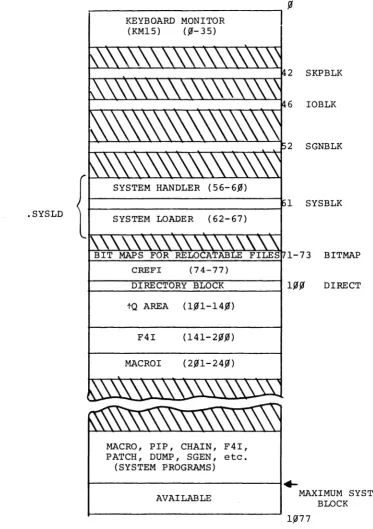
A diagram of .the allocation of a typical 8K system on a
DEC-tape is given in Figure 3-1.
Referencing Figure 3-1, programs CREFI1, MACROI, and F4I are
present only in 8K systems; in larger systems these programs
are overlayed by the fQ area, if i t is kept, or their areas
are freed. Areas freed by the deletion of system programs or
by the deletion of the tQ area are opened for use by
relocat-able programs.
As shown in Figure 3-1, the tape area occupied by system
pro-grams is located at the end of the system area. The system
program area is automatically expanded or contracted by SGEN
to accommodate the addition or deletion of system programs.
The overall area occupied by the system can be reduced by
the re-specification of the system maximum block number;
this is permitted by SGEN and results in the movement of the
system program area closer to the front of the tape.
Shorten-ing the overall system length in this manner reduces the area
available for relocatable files; however, this may be compensated
INOTE: CREFI is a 4-block area which is reserved for a
for by the deletion of unused relocatable files and the
dele-tion of the tQ area. Normally, loading the monitor and a
system program is accomplished in the following manner: the
monitor is read into core from the top of the system tape by
the bootstrap; the monitor, in turn, uses the bootstrap to
load the SKPBLK and IOBLK areas.
The monitor and the skip and I/O areas are located on the
system tape in a sequential order and are spaced to permit
their being read in a single continuous forward movement of
the system tape.
Nhen the monitor receives a load system program ( SYS program)
command, i t reads into core the system loader (.SYSLD) using
the bootstrap loader. The .SYSLD loader then reads,
select-ively, the required system program handlers from the system
library (.LIBR BIN). Nhen the handlers are loaded into core,
the bootstrap is then set up to load the requested system
pro-gram. The placement on the system tape of .SYSLD with respect
to .LIBR BIN and the organization of the handlers within the
library permits the needed handlers to be read in a continuous
forward movement of the system tape. The forward movement of
the tape is continued through the tape System Program area
during which the requested system program is read into core.
The first .SYS program in the system program area is the first
reached during the read operation; therefore, i t will have the
shortest possible load time. As illustrated in the above
description, the contents of the system tape are organized to
implement an efficient loading scheme. Loading efficiency for
an individual system, however, can be further enhanced by:
1. Shortening the system physical length by
deleting unwanted relocatable files and
the f Q area and specifying a smaller
maximum system block;
2. Re-ordering system programs to put the
NOTES: 1)
ISSS \I
indicates areas reserved for relocatable files. 2) All numbers are given in octal..SYSLD
II
~---~I
KEYBOARD MONITOR (KM15) (~-35)
1 SYSBLK
r---,
t-==...:..:;:..=....=--;;....;;..=-=:;.;;...====--;..;;:.;=~. 1-73 BITMAP
CREFI
DIRECTORY BLOCK Inn
r---~~~~~~---1 pp
tQ AREA (1~1-14~)
F4I (14l-2~.m)
MACROI (2~1-24~)
MACRO, PIP, CHAIN, F4I, PATCH, DUMP, SGEN, etc.
(SYSTEM PROGRAMS)
~---~~
DIRECT
AVAILABLE MAXIMUM SYSTEM
BLOCK
[image:46.599.127.501.38.567.2]APPENDIX A SGEN ERROR MESSAGES
The error messages which may be output by SGEN during its opera-tions are described in the following table.
Printout
?
(query repeated)
SYM ONLY (query repeated)
X
"Y"/"N"
(query repeated)
OCTAL
*
(query repeated)TOO LONG (query repeated)
Table A-I SGEN Error Messages Meaning
GENERAL PURPOSE ERROR PRINTOUTS
The preceding query response was not intelligible; this indicator (?) is normally followed by a reprint of the query incorrectly responded to.
The preceding entry contained or was comprised of a numeric where a symbol was required.
The preceding entry was faulty and has been ignored by SGEN; normally this indication follows a text error message. For example:
BAD DEVICE CODE
X>
The preceding response should have been either a yes (Y) or a no (~)
and was incorrectly-made.
An octal number was expected as the preceding response and was not re-ceived.
One of the preceding entry symbols was too long; i t exceeded nine
charac-ters.