SIMULATION OF AVIONICS ELECTROMAGNETIC
SHIELDING EFFECTIVENESS BASED ON MODAL MOM
YAJUN XU
Civil Aviation Flight University of China,Aviation Engineering Institute, Civil Aviation Flight University
of China,Guanghan Sichuan,China (618307),086-0838-5182655 E-mail: [email protected]
ABSTRACT
In this paper, an efficient technique based on modal method of moments (MoM) is presented, the influence of apertures’ shape and calculation point of SE on electromagnetic shielding effectiveness has been studied. A very good agreement among the simulation results of the proposed technique, results available in the literature and experimental results is observed. The results of the present analysis show that electric field SE is seriously affected by calculation points and aperture shape. These useful results gained in this paper have important practical significance to improving the electric field shielding effectiveness of shielding cavity.
Keywords: Rectangular Enclosure, Apertures, SE, Mom, Green’s Function
1. INTRODUCTION
In the past most aircraft used a series of cables, chains, cranks, and mechanical mechanisms to operate the systems which gave the aircraft its ability to fly. With the advent of the transistor many mechanical devices have been replaced or augmented with electronic circuits. Electronic circuits have increasingly been designed and used for flight critical aircraft control systems, due to their ability to accurately control complex functions and increase reliability. Electronic circuits, however, not only respond to their internal electrical signal flow, but may respond to any input which can couple into the wire bundles, wires, IC leads, and electrical junctions. The Electromagnetic Environment (EME) is one of these inputs that by its nature has access to all these electronic circuits and may result in disabling effects called Electromagnetic Interference (EMI).The aircraft skin and structure have also evolved. The classic aircraft is made of aluminum and titanium structure with an aluminum skin. Modern technology and the desire to develop more efficient aircraft have driven the introduction of epoxy structure, carbon-epoxy skins, and aramid fiber-carbon-epoxy skins in civil aircraft. Aluminum may be a good EM shield against HIRF and hence electronic circuits which are provided inherent protection. However, some
composites are poor EM shields, causing HIRF to irradiate the electronic systems on such aircraft with relatively little attenuation. So electromagnetic shielding is an important technique in electromagnetic compatibility (EMC). It can restrain electromagnetic energy radiation and prevent the electromagnetic interference effectively.
Metallic shielding enclosures are frequently employed to protect against radiation from both external EM fields and electromagnetic leakage from interior components. However, the integrity of these enclosures is often compromised by apertures of various sizes and shapes used to accommodate visibility, ventilation or access to interior components, such as input and output connections, control panels, visual-access windows, ventilation panels, etc. Since these apertures at appropriate electromagnetic frequencies behave as very efficient antennas, they also become sources of electromagnetic interference problems for both EM emission and susceptibility.
Nowadays the EM shielding effectiveness has becoming a hot research area.
Robinson et al. [1, 2] introduced a very simple analytical method based on transmission line model. However, this approach is limited by the assumption of thin apertures, simple geometries, negligible mutual coupling between apertures and fields can be calculated only at points in front of the aperture. In past years, some numerical techniques have been applied to the analysis of shielding effectiveness, such as finite difference time domain (FDTD) [3, 4] finite element method (FEM) [5, 6] method of moments (MoM) [7, 8] transmission line matrix (TLM) [9, 10] and hybrid method[11] are utilised with good accuracy over a broad frequency band at the cost of large amount of computer memory and CPU time. Deshpande introduced a moment method technique(modal MoM) using entire domain basis functions to represent apertures fields and therefore the magnetic currents on the apertures, which can evaluate the SE of a zero thickness enclosure exposed to a normally incident plane wave accurately at the center inside enclosure[12].
In this paper the modal MoM solution is formulated and by employing the surface equivalence principle and boundary conditions at each end of the aperture. The shielding effectiveness of enclosure with different shapes apertures are calculated at many other points inside the cavity. A very good agreement among the results of the proposed technique, results available in the literature and experimental results is observed.
2. ELECTROMAGNETIC PROBLEM
The shielding effectiveness of an enclosure is defined as
E-shielding (dB)= -20log(|Eint|
|Eext|) (1)
WhereEintis the electric field at a given point inside the enclosure and Eextis the field at the same point in the absence of the enclosure. Therefore, the problem of estimation of shielding effectiveness is
essentially the problem of calculating the cavity fields excited by a plane wave incident from free space upon the shielding enclosure.
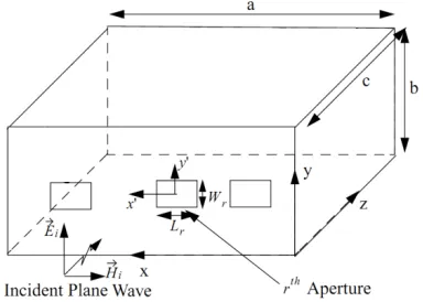
[image:2.612.324.516.221.358.2]Figure 1 shows a rectangular enclosure with rectangular apertures exposed to a normal incident plane wave. The dimensions of the cavity are a×b×c. There are r number of apertures and the dimensions of the rth aperture are L_r× W_r. The orientation of the reference axes is also shown with the origin at the lower right corner of the front wall.
Figure 1. Geometry Of Rectangular Enclosure With Rectangular Apertures Exposed To A Normal Incident
Plane Wave
2.1. Apertures Fields And Equivalent Magnetic Currents
In the modal MoM formulation, we assume that the apertures are relatively small compared to the walls in which they are located and are placed far enough away from the edges of the enclosure. In addition, the edge diffracted fields are neglected. These assumptions enable us to use image theory and equivalence principles, using the surface equivalence principle, the apertures both internal and external to the enclosure can be replaced by equivalent magnetic currents of
M=n E× apt
(2)
Where Eaptis the aperture electric field and n is the aperture normal vector.
1
ˆ sin cos
2 2
E ( 0)
ˆ cos sin
2 2
r r
rpq cr cr
R
p q r r
apt
r r r
rpq cr cr
p q r r
L W
p q
y U x x y y
L W
z
L W
p q
x V x x y y
L W
π π
π π
=
+ − × + −
= =
+ + − × + −
∑∑
∑
∑∑
(3)
Where Urpqand Vrpqare the unknown amplitudes of the pqth mode of magnetic current on the outer of the rth aperture, Urpq≠ 0 and Vrpq≠ 0for
xcr−L2r≤ x ≤ xcr+L2r, ycr−W2r≤ y ≤ ycr+W2r,
[image:2.612.144.524.618.708.2]Lr and Wrare the length and width of rth
aperture, xcrand ycr are center coordinates of the rth aperture.x�, y�are the unit vectors in x, y directions.
The unknown amplitudes UrpqandVrpq are determined by setting up coupled integral equations.
Using the equivalence principle, the equivalent magnetic currents are
Mapt= n1× Eapt= -z� × Eapt(z=0)
=∑ �x� ∑ ∑ Ur=1R p q rpqΨr-y� ∑ ∑ Vp q rpqΦr� (4)
=∑Rr=1Mr1
Where
Ψr =sin (pπLr(L2r+ x − xcr))× cos �Wqπr�W2r+ y −
ycr�� (5)
Φr=cos (pπLr(L2r+ x − xcr))× sin �Wqπr�W2r+ y −
ycr�� (6)
2.2. Electromagnetic Field Outside Enclosure
Consider the aperture on the z=0 plane, the scattered EM field outside due to the rth aperture can be determined by solving electric vector potential
E=-1
𝜀0𝛻×F (7)
H=-jω k02(k0
2
F+𝛻𝛻∙F) (8)
Where the electric vector potential F is given by
F=4π � 2Mε0 r apt
e-jk0�r-r'�
r-r' ds (9)
Superposition of the scattered electromagnetic field due to all apertures on the z=0 plane gives the total scattered field as[12]
ExI= � � �-V4πrpq2 q p R
r=1
� � e-jkz�z-z'�
∞
-∞ ∞
-∞
ϕrpqyejkxx+jkyydkxdky (10)
EyI= � � �-U4πrpq2 q p R
r=1
� � e-jkz�z-z'�
∞
-∞ ∞
-∞
ψrpqyejkxx+jkyydkxdky (11)
EzI= � � �4π-12 q p R
r=1
� � e-jkz�z-z'�
∞
-∞ ∞
-∞
Vrpqϕrpqykx+Urpqψrpqyky
kz e
jkxx+jkyydkxdky (12)
In expressions (10)-(12) ϕrpqy is the Fourier transform of Φrpqy and ψrpqy is the Fourier transform ofΨrpqx.
2.3. Electromagnetic Field inside Enclosure
The equivalent magnetic currents, present on the apertures of the enclosure, radiate electromagnetic
fields inside the enclosure. The total electromagnetic field at any point inside enclosure is obtained by a superposition of fields due to each equivalent magnetic current source. considering the x- component of the magnetic current and using dyadic Green’s function, The total magnetic field inside the enclosure is then obtained from [12] as
Hx IIx0
=-jω
k02∑ ∑p,qUrpq R
r=1 ∑ -ε0
kI ∞ m,n
ε0mε0n
ab sin(kIc)�k0 2
-�mπ
a� 2
�× sin�mπx
a �cos( nπy
b )cos(kI(z-c))Irpqmnx (13)
Hy IIx0
=-jω
k02∑ ∑p,qUrpq R
r=1 ∑ -ε0
kI
∞ m,n
ε0mε0n
ab sin(kIc)
mπ a
(-nπ b)× cos�
mπx a �sin�
nπy
b �cos�kI�z-c��Irpqmnx (14)
HzIIx0=-jωk
0
2∑Rr=1∑ Up,q rpq∑∞m,n-εkI0ab sin(kε0mε0nIc)mπa (-kI)× cos�maπx�cos� nπy
b�sin�kI�z-c��Irpqmnx (15)
In (13)-(15),
Irpqmnx=sin�
mπx'
a �×cos( nπy'
Likewise, considering the y-component of the magnetic current and using the proper boundary
conditions, The total magnetic field inside the enclosure is then obtained from [12] as
HxIIy0=-jωk02∑r=1R ∑ -Vp,q rpq∑∞m,n-εk0Iab sin(kε0mε0nIc)(-mπa )nπb × sin �mπxa � cos(nπyb )cos(kIr�z-c�)Irpqmny (16)
HyIIy0= -jω
k02∑ ∑
-Vrpq
p,q R
r=1 ∑ -ε0
kI ∞ m,n
ε0mε0n ab sin(kIc)�
k0 2
-�nπ
b� 2
�× cos�mπx
a �sin( nπy
b )cos(kI(z-c))Irpqmny (17)
HzIIy0= -jω
k02∑ ∑
-Vrpq
p,q R
r=1 ∑ -ε0
kI ∞ m,n
ε0mε0n ab sin(kIc)
nπ
b(-kI)× cos�
mπx a �cos(
nπy
b )sin(kI�z-c�)Irpqmny (18)
In (16)-(18),
Irpqmny=∬q Φrpqy(x',y')cos� mπx'
a �sin( nπy'
b )dx 'dy'
For a unique solution the electromagnetic fields in various regions satisfy continuity conditions over their common surfaces. The tangential electric fields over the apertures are continuous. The tangential magnetic over the apertures also must be continuous ,thus yielding coupled integral equations with the magnetic currents as known variables. The coupled integral equation in conjunction with the method of moments can be solved for the amplitudes of magnetic currents.
2.4. Derivation of Integral Equation
The total tangential fields inside the cavity from apertures are written as
HxII= HxIIx0+HxIIy0 (19)
HyII = HyIIx0+ HyIIy0 (20)
Applying the continuity of tangential magnetic field on the z =0 plane yields
HxI|z=0+Hxi|z=0=HxII|z=0 (21)
HyI|z=0+ Hyi|z=0= HyII|z=0 (22)
Now selecting Ψr′p′q′x as a testing function and use of Galerkin’s method reduces the (21) to
Ir'p'q'xi= � � (UrpqYrpqrx1x1'p'q'+VrpqYrpqrx1y1'p'q') (23)
p,q R
r=1
Where
Yrpqrx1x1′p′q′=−jωk
0
2 ∑∞m,n=0−εkI0ab sin(kε0mε0nIc)(k02− �mπ
a �
2
)cos (kIc) IrpqmnxIr′p′q′mnx
+ 𝜔𝜀0
4𝜋2𝑘 0
2∫ ∫ 𝛹−∞+∞ 𝑟𝑝𝑞𝑥𝛹𝑟∗′𝑝′𝑞′𝑥 +∞
−∞
𝑘02−𝑘𝑥2
𝑘𝑧 𝑑𝑘𝑥𝑑𝑘𝑦 (24)
Yrpqrx1y1′p′q′=jωk 0
2∑∞m,n=0−εkI0ab sin(kε0mε0nIc)(−mπa )(nπb)cos (kIc)IrpqmnyIr′p′q′mnx
+ ωε0
4π2k 0
2∫ ∫ ϕ−∞+∞ −∞+∞ rpqyψr∗′p′q′x −kxky
kz dkxdky (25)
Ir′p′q′xi=∬r′p′q′HxiΨr′p′q′xdxdy (26)
Similarly, selecting −Φr′p′q′y as a testing function and use of Galerkin’s method reduces the (22) to
Ir'p'q'yi= ∑r=1R ∑ (Up,q rpqYrpqry1x1'p'q'+VrpqYrpqry1y1'p'q') (27)
Where
Yrpqry1x1′p′q′=jωk 0
2∑∞m,n=0−εkI0ab sin(kε0mε0nIc)�mπa� �−nπb� cos(kIc) IrpqmnxIr′p′q′mny
+ωε0
4π2k 0
2∫ ∫ ψ−∞+∞ rpqxϕr∗′p′q′y +∞
−∞
−kxky
kz dkxdky (28)
Yrpqry1y1′p′q′=−jω
k02∑
−ε0
kI
∞
m,n=0 ab sin(kε0mε0nIc)�k02− �nπb� 2
� cos (kIc)IrpqmnyIr′p′q′mny
− ωε0 4π2k 0
2 � � ϕrpqy +∞
−∞ +∞
−∞
ϕr∗′p′q′y(k0
2− k
x 2)
Ir′p′q′yi=∬r′p′q′HyiΦr′p′q′xdxdy (30)
Equation (23) and (27) can be written in a matrix form as
⎣ ⎢ ⎢ ⎢
⎡Yrpqrx1x1′p′q′ Yrpqr′p′q′ x1y1
Yrpqry1x1′p′q′ Yrpqry1y1′p′q′ ⎦ ⎥ ⎥ ⎥ ⎤
�UVrpq
rpq� = �I r′p′q′xi
0 � (31)
For normal incidence
Ir′p′q′xi=
⎩ ⎪ ⎨ ⎪ ⎧
HxiWr�1 − cos(p ′π)
p′π
Lr′
� � , for(q
′= 0)
0, for(q′≠ 0)
Using the orthogonality of expansion functions it can be shown Yrpqry1x1′p′q′=Yrpqrx1y1′p′q′= 0, hence
equation (31) simplifies to
�Yrpqrx1x1′p′q′�[Urpq]=[Ir′p′q′xi] (32)
The matrix equation (32) can be numerically solved for the unknown amplitudes of equivalent magnetic currents induced on the apertures due to given incident field. From the knowledge of these amplitudes electromagnetic field inside as well as outside the enclosure can be obtained.
3. VALIDATION OF THE PRESENT
TECHNIQUE
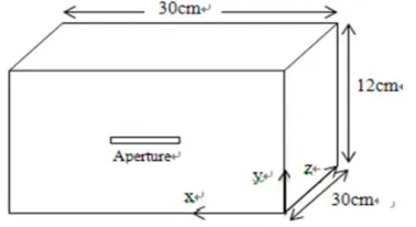
[image:5.612.90.294.144.278.2] [image:5.612.320.512.202.337.2]In this section, we consider a rectangular enclosure of size (30cm × 12𝑐𝑚 × 30𝑐𝑚) with a rectangular aperture of size (10cm ×0.5cm) located at the center of the front wall (15cm, 6cm, 0) for the validation of the present technique, as illustrated in Figure 2. The enclosure is illuminated by a normal incident plane wave at 0 polarization.
Figure 2. Geometry Of 30cm×12cm×30cm Enclosure With A Single Aperture At (15cm, 6cm, 0)
Assuming only expansion mode on the aperture and considering only dominant mode inside the cavity. The shielding effectiveness is calculated at the center of the cavity. Electric field shielding
[image:5.612.100.289.550.653.2]obtained using expression (32) is plotted in Figure 3 along with the results from [2]. It is observed that the numerical data obtained using the present method agrees well with the earlier published results. Experimental data from [2] is also reproduced in Figure 3.
Figure 3. Electric field Shielding At The Center Of 30cm×12cm×30cm Enclosure10cm×0.5cm Aperture Located At 15cm×6cm In Z=0 Plane With Dominant
Cavity Mode Considered.
4. RESULTS AND DISCUSSION
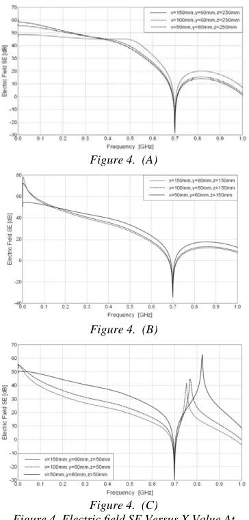
In this section, in order to study the electric field shielding of different points in the cavity, the same geometry with Figure 2 is selected. The enclosure is illuminated by a normal incident plane wave at 0 polarization. The shielding effectiveness with dominant cavity mode considered is also calculated at many different points in the cavity.
inside the enclosure should be placed at the points far away from the apertures, which can improve the ability of electromagnetic compatibility.
Figure 4. (A)
Figure 4. (B)
Figure 4. (C)
Figure 4. Electric field SE Versus X Value At Different Plane Of 30cm×12cm×30cm Enclosure With 10𝑐𝑚 ×0.5cm Aperture Located At 15cm×6cm
In Z=0 Plane.
In this section, we discuss electric field SE results calculated at three different points versus different shapes apertures. We also consider a 30cm × 12cm × 30cm enclosure with rectangular aperture of size (10 cm × 0.5cm, 5.0 cm × 1.0cm and 2.23cm ×2.23cm) located at the center of the front wall (15cm, 6cm, 0) respectively. The enclosure is illuminated by a normal incident plane wave at 0 polarization.
Figure.5 (a), (b) and (c) presents three plots of electric field SE versus three different shapes aperture with same area respectively. We observe a similar changed trend in Figure.5 (a), (b) and (c) that all the resonance frequency is about 0.7 GHz, electric field SE increase in turn from
10.0cm×0.5cm aperture to 2.23cm×2.23cm aperture and electric field SE have a rapid increase up to about 50dB at 0.75GHz at z=50mm because of modal structure of the fields. Figure.5 confirms the electric field SE dependence upon distance from the apertures. We also note that the apertures with different shape but same area have different effect on electric field SE. For one aperture case, from discussed above, we can conclude that square aperture have higher electric field SE than rectangular aperture when their area is same.
Figure 5(A) Electric field SE Calculated At Z=150mm, X=150mm,Y=60mm
Figure 5(B) Electric field SE Calculated At Z=250mm, X=150mm,Y=60mm
Figure 5(C) Electric field SE Calculated At Z=50mm, X=150mm,Y=60mm
Figure 5. Electric field SE Calculated At Different Points Inside 30cm×12cm×30cm Enclosure With A
[image:6.612.104.286.133.513.2] [image:6.612.319.524.198.684.2]5. CONCLUSION
In this paper, the influence of the calculation point of SE and apertures’ shape on electromagnetic shielding effectiveness has been investigated. The modal MoM solution is formulated, and by employing the surface equivalence principle and boundary conditions at each end of the aperture, the problem is solved. Simulation results are well agreed with data available in the literature. The results of the present analysis show that lower electric field SE near the aperture than at location inside the enclosure farther away from the aperture, the electric field SE is also seriously affected by aperture shape. These useful results gained in this paper have the important practical significance to improv the electric field shielding effectiveness of shielding cavity.
REFERENCES
[1] M.P. Robinson, J.D. Turner, D.W.P. Thomas, Etc. Shielding effectiveness of a rectangular enclosure with a rectangular aperture. Electron. Lett. 1996; 32(17):1559-1560.
[2] M.P. Robinson, T.M. Benson, C. Christopoulos, Etc. Analytical formulation for the shielding effectiveness of enclosures with apertures. IEEE Transactions on Electromagn Compatibility. 1998; 40(3): 240–248.
[3] LIM., NUEBEL J., DREWNIAK J.L, Etc. EMI from cavity modes of shielding enclosures – FDTD modeling and measurements. IEEE Transactions on Electromagn Compatibility. 2000; 42(1):29–38.
[4] M. Li, J. Nuebel, J. L. Drewniak, T. H. Hubing, Etc. EMI from cavity modes of shielding enclosures—FDTD modeling and measurements. IEEE Transactions on Electromagn Compatibility. 2000; 42(1): 29– 38.
[5] BENHASSINE S., PICHON L., TABBARA W. An efficient finite-element time-domain method for the analysis of the coupling between wave and shielded enclosure. IEEE Transactions on Magnetics. 2002; 38(2): 709–712.
[6] W. P. Carpes Jr., L. Pinchon, and A. Razek.Analysis of the coupling of an incident wave with a wire inside a cavity using an FEM in frequency and time domains. IEEE Transactions on Electromagn Compatibility. 2002; 44(3): 470–475.
[7] WALLYN W., DE ZUTTER D., ROGIER H. Prediction of the shielding and resonant behavior of multisection enclosures based on magnetic current modeling. IEEE Trans. IEEE Transactions on Electromagn Compatibility. 2002; 44 (1):130–138.
[8] G. Wu, X.-G. Zhang, Z.-Q. Song, and B. Liu . Analysis on Shielding Performance of Metallic Rectangular Cascaded Enclosure with Apertures. Progress In Electromagnetics Research Letters. 2011; 20: 185-195.
[9] PODLOZNY V., CHRISTOPOULOS C., PAUL J. Efficient description of fine features using digital filters in time domain computational electromagnetics. IET Sci. Meas. Technol.,2002, 149(5): 254–257.
[10] R. Attari , K. Barkeshli. Application of the transmission line matrix method to the calculation of the shielding effectiveness for metallic enclosures. in Proc. IEEE Antennas Propagation Soc. Int. Symp. Texas. 2002: 302– 305.
[11] Wu,G.Zhang,X.G.;Liu,B. A Hybrid Method for Predicting the Shielding Effectiveness of Rectangular Metallic Enclosures with Thickness Apertures. Journal of Electromagnetic Waves and Applications. 2010; 24(8):1157-1169. [12] Electromagnetic field penetration studies
![Assessment of Physiological Health Status in Relations to Different Anthropometric and Cardio respiratory Measures of Head Supported Load Carrying Male Porters of Sikkim, India [Article Retracted]](data:image/gif;base64,R0lGODlhAQABAIAAAP///wAAACH5BAEAAAAALAAAAAABAAEAAAICRAEAOw==)