ARTIFICIAL BEE COLONY (ABC) AND NEURAL
NETWORK BASED OPF TECHNIQUE WITH FACTS
CONTROLLER
1M.KARTHIKEYAN, 2P.AJAY-D-VIMAL RAJ 1Research Scholar PRIST University, Thanjavur
2Assistant Professor Department of Electrical and Electronics Engineering,
Pondicherry Engineering College, Pondicherry University, Pondicherry, India E-mail:1[email protected] , 2[email protected]
ABSTRACT
In the paper, hybrid technique for solving optimal power flow problems that occur in power systems. The proposed hybrid technique is the combination of artificial bee colony (ABC) algorithm and artificial intelligence (AI) technique. The purpose of the ABC algorithm is used to optimize the optimal operating range of generation limits. So, the fuel cost and the emission of the power generation system is maintained economically. Because, the ABC is an optimization algorithm based on the intelligent foraging behaviour of honey bee swarm. Here, the artificial neural network (ANN) is used as an AI technique. ANN is one of the AI techniques which used for determining the optimal injected voltage magnitude and voltage angle of UPFC. The optimal placement of UPFC is depends on the power flow deviation and the combination of the power system buses. Using the propose hybrid OPF technique, the optimal power flow of the power system is maintained. The proposed hybrid technique is implemented in MATLAB working platform and the power flow parameters are evaluated. The performance of the hybrid technique is compared with ABC algorithm.
Keywords: OPF, Hybrid Technique, FACTS Controller, UPFC, ABC Algorithm, AI Technique, ANN, Power Loss.
1. INTRODUCTION
A power system is a set of connections through which energy is transmitted from generators to load. It signifies the association between current and voltage at nodes [2]. In current power system, which is a composite network comprising of several generators, transmission lines, variety of loads and transformers [1]. Providing a dependable power supply with cheapest cost is the main intention of power system [9]. The change of power between different energy carriers launches a coupling of the related power flows resulting in system interactions [8]. Precise and detailed constancy study is a significant matter for power system planning and operating tasks [11]. Normally, Power systems contain OPF problem, hence constancy may happen. Constancy depends upon both the original operating conditions of the system and the sternness of the disturbance [1].
The OPF is a main problem for power generation in the current generation, and it is in common non-convex [6]. The OPF is a fixed nonlinear programming problem which optimizes a definite
objective function while gratifying a set of physical and operational controls [20] [6]. The constraints for OPF contain: (i) the AC power flow constraints, (ii) bounds on power generation, (iii) bounds on bus voltage magnitudes, (iv) bounds on line voltage drops, and (v) limits on power transfer on lines [13]. The objective of a power flow problem is to attain the entire voltage angle and magnitude information for every bus in a power system for precise load and generator actual power and voltage condition [3]. Optimal power flow (OPF) problem contracts with finding an optimal operating point of a power system that minimizes an apt cost function such as generation cost or transmission loss on power and voltage variables [14][15].
by weighted sum, constraint strategy and goal attainment technique [18]. Several optimization methods have been implemented and applied to work out the OPF problem through, fuzzy emissions constraints, particle swarm optimization, evolutionary algorithm, iterative approach, genetic algorithm and computational intelligence methods [4]. In the OPF problem, which finds out approximately all of changeable variables, such as; power outputs of generators, transformers tap positions, phase shifter angle positions, shunt capacitor /reactor, etc. [5].
At the instant, to discover and classify different types of OPF events or commotions, a number of OPF maintaining techniques have been suggested. For OPF problem, diverse techniques are applied by the researchers [16]. Interior point methods, modified Primal–Dual Logarithmic-Barrier Method, Successive Quadratic Programming Method are moreover utilized for enhancing OPF [10]. Asymptotic numerical method (ANM) is extremely competent. Currently, ANM has been used with great achievement in an extensive range of problems chiefly in the regions of Continuation Power Flow (CPF), which is a great impact on the voltage constancy study [12]. A competent heuristic algorithm is to work out the optimal capacitor placement problem in radial distribution systems [17].
This document, a hybrid optimal power flow method with FACTS controller is suggested. The suggested hybrid method is the mixture of ABC algorithm and artificial neural network. ABC is one of the swarm intelligence based algorithm which applied to choose the optimal generation limits of the system. The optimal generation limits are found out based on the minimum value of the fuel cost and the emission. For reducing the actual power deviation of system by inserting the voltage magnitude and voltage angle, the UPFC is employed as a FACTS controller. The fitting cost of the UPFC is depends on the actual power deviation of the system. The detailed explanation of the suggested hybrid method and the UPFC power flow model are explained in section 3. Earlier to that, the current research works are offered in section 2. The consequences and the conversation are offered in section 4. In section 5 the paper is finishes.
2. RECENT RESEARCH WORKS: BRIEF REVIEW
A number of research works associated to OPF problem working out based on Goal Attainment method, PSO techniques are previously obtainable in the literature. In this segment, some of the most current literature works on this topic are assessed. A multi-objective harmony search (MOHS) algorithm for optimal power flow (OPF) problem has been improved by S. Sivasubramani et al. [21]. OPF problem was created as a nonlinear constrained multi-objective optimization problem where diverse objectives and different constraints have been regarded in the formulation. To find and administer the Pareto optimal front, fast elitist non-dominated sorting and crowding distance have been employed. The fuzzy based mechanism has been applied to choose a compromise result from the Pareto set. Their Simulation results are moreover compared with fast non-dominated sorting genetic algorithm (NSGA-II) technique. Their suggested method created true and well allocated Pareto optimal solutions for OPF problem.
By means of an algorithm of implanting sensitivity theory in ordinal optimization, Shieh-Shing Lin et al. [22] have suggested to work out a class of NP-hard problem. The decentralized optimal power flow with nonstop and distinct control variables problem was initially created as a NP-hard optimization problem - Block Additive constrained with Continuous and Discrete variables (BACD) problem. Secondly, an algorithm of implanting sensitivity theory (ST) in ordinal optimization (OO), abbreviated as STOO, was suggested for working out this NP-hard optimization problem. Their suggested technique contains three stages and three models of presentation assessment. The STOO algorithm attained a good adequate result with smaller objective value and devoured less CPU time than four heuristic methods.
grid partitioning and adding incentive to electrical variables of boundary nodes.
To work out power flow problems under both load and line data uncertainty, interval arithmetic in current injection power flow analysis has been suggested by L.E.S. Pereira et al. [24]. Using Krawczyk technique, the resulting interval nonlinear system of equations was worked out. The control proposals were executed in Matlab environment by means of the Intlab toolbox. They have verified that their Methodology was very effortless and dependable, and meets with a small number of iterations.
A semi definite programming (SDP) technique to work out the optimal power flow problem has been suggested by Xiaoqing Bai et al. [25]. At first, the non-convex OPF problem was altered into its convex SDP model and the matrix variable of SDP was re-arranged by means of the chordal extension of its combined sparsity pattern of the graph partitioning method. Their suggested technique has to be diminished the consumption of computer memory and develop the computing presentation considerably but less CPU time and remembrance.
Lashkar Ara, A. et al. [26] have progressed a suitable models of flexible ac transmission systems (FACTS) shunt-series controllers for multiobjective optimization and furthermore offers a multiobjective optimization methodology to locate the optimal location of FACTS shunt-series controllers. The objective purposes were the total fuel cost, power losses, and system load ability with and without minimum cost of FACTS fitting. For the multiobjective mathematical programming (MMP) formulation, the ε-constraint strategy was executed together with the FACTS shunt-series controllers, hybrid flow controller (HFC), and unified power-flow controller (UPFC)). The simulation consequences were offered for the IEEE 14-bus system.
To reduce the generator fuel cost in optimal power flow (OPF) control with multi-line stretchy alternating current transmission systems (FACTS) tool which was interline power flow controller (IPFC), an intelligent search evolution algorithm (ISEA) has been suggested by A. V. Naresh Babu et al. [27]. In the suggested algorithm, a two step initialization process have been implemented which removes the mutation operation and moreover it gives optimal solution with less number of generations nothing like the OPF solution techniques presented in the literature. The suggested algorithm has been inspected and
checked on a standard IEEE-30 bus system without and with IPFC. The test results were representing that the suggested algorithm with IPFC could find better result than without IPFC.
The latest research works illustrates that, more than a few methods are applied to work out the optimal power flow problems. In the earlier period, researchers spotlighted on how to create some practical constraints, such as bus voltage range, generation limits, line transfer capability, possibility constraints, fuel cost environment concerns etc. For working out the optimal power flow problem, Genetic Algorithm is applied. The main drawback of GAs is the high CPU time implementation and the qualities of the solution decline with practical large scale optimal power flow (OPF) problems. The multi objective OPF problem is worked out by Goal Attainment technique, weighted sum method and ϵ-constraint method. The aforementioned techniques need multiple steps to attain an optimal solution and require much computational time. Due to this reason the optimal power flow problem is not able to uphold successively. Sensitivity Theory in Ordinal Optimization (STOO) is moreover applied for working out OPF problem. This technique is only appropriate for smaller objective value of OPF problem; it is not appropriate for the larger objective value of OPF. In the document, a hybrid method with FACTS controller based OPF technique is suggested. The detailed explanation of the suggested method is explained in the subsequent section.
3. EQUIVALENT CIRCUIT AND POWER FLOW MODEL OF UPFC
UPFC equivalent circuit
equivalent circuit model [29] are illustrated in Figure 1 and Figure 2 respectively.
[image:4.595.97.505.495.755.2]Figure 1: UPFC installed power system.
Figure 2: Equivalent circuit of UPFC.
The injected voltage and voltage angle of UPFC are represented as Vinj and
inj
θ respectively. The
injected voltage of the UPFC is depends on the shunt injected voltage
(
Vinj(sh))
and series injected voltage(
Vinj(se))
. The injected voltage of UPFC is determined by follow [30]:) ( )
(sh injse inj
inj V V
V = + (1)
(
)
{
}
{
(cos sin )}
sin cos ) ( ) ( ) ( ) ( ) ( ) ( se inj se inj se inj sh inj sh inj sh inj inj j V j V V θ θ θ θ + + = (2)
Where, Vinj∈Vinjmin ≤Vinj ≤Vinjmax and
max min
inj inj inj
inj θ θ θ
θ ∈ ≤ ≤ are the control able
injected voltage and voltage angle of the converter. The control voltage is depends on the shunt and series injected voltage of the system.
UPFC power flow equation
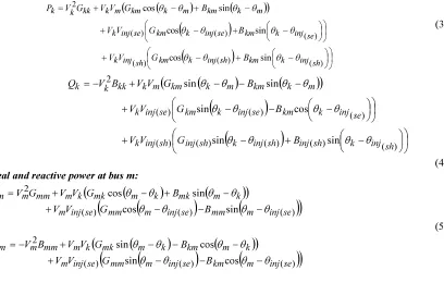
From the above equivalent circuit model, the power injection equations are derived from the power flow studies. By using load flow analysis in Figure 2, the real and reactive power of bus and
are determined. Similarly, the real and reactive powers injected by the coupling transformer are calculated. The important of the power injection representation is that the symmetric characteristics of admittance matrix will not be destroyed [31]. The equations are described as following them,
Real and reactive power at bus k
(
)
(
)
(
)
(
)
(
)
− + − + − + − + − + − + = ) ( ) ( ) ( ) ( ) ( ) ( 2 sin cos sin cos sin cos sh inj k km sh inj k km sh inj k se inj k km se inj k km se inj k m k km m k km m k kk k k B G V V B G V V B G V V G V P θ θ θ θ θ θ θ θ θ θ θ θ (3)(
)
(
)
(
)
(
)
(
)
− + − + − − − + − − − + − = ) ( ) ( ) ( ) ( ) ( ) ( ) ( ) ( 2 sin sin cos sin sin sin sh inj k sh inj sh inj k sh inj sh inj k se inj k km se inj k km se inj k m k km m k km m k kk k k B G V V B G V V B G V V B V Q θ θ θ θ θ θ θ θ θ θ θ θ (4) Real and reactive power at bus m:(6) Series converter injected real and reactive power:
(
)
(
)
(
)
(
)
(
)
(
mm inj se m mm inj se m)
m se inj k se inj km k se inj mk k se inj mm se inj se inj B G V V B G V V G V P θ θ θ θ θ θ θ θ − − − + − + − + = ) ( ) ( ) ( ) ( ) ( ) ( 2 ) ( ) ( sin cos cos cos (7) (8)
(
)
(
)
(
)
(
)
(
)
(
mm injse m mm inj se m)
m se inj k se inj km k se inj km k se inj mm se inj se inj B G V V B G V V G V Q θ θ θ θ θ θ θ θ − − − + − + − + − = ) ( ) ( ) ( ) ( ) ( ) ( 2 ) ( ) ( cos sin cos sin
Shunt converter injectedreal and reactive power:
(
)
(
)
(
inj sh inj sh k inj sh injsh k)
k se inj sh inj sh inj sh
inj V G V V G B
P =− 2 ( )+ ( ) ( ) θ ( )−θ + ( ) θ ( )−θ )
( )
( cos sin
(9)
(
)
(
)
(
injsh inj sh k inj sh inj sh k)
k sh inj sh inj sh inj seinj V G V V G B
Q =− + θ −θ + θ −θ
) ( ) ( ) ( ) ( ) ( ) ( 2 ) ( )
( sin cos (10)
Where,
kk kk
kk G jB
Y = +
mm mm
mm G jB
Y = +
mk mk
mk
km
Y
G
jB
Y
=
=
+
(11) )( )
( )
(sh injsh inj sh
inj G jB
Y = +
) ( ) ( )
(se injse inj se
inj G jB
Y = +
The above described equation (11) is the admittance values of the bus, between the buses and power converters. The real power loss of the converter is assumed as loss less then; the converter equation is changed as follow:
0 ) ( )
(sh + inj se = inj P
P (12) The above real power mismatch equations are used as the guiding principle for conducting limit revisions. The control parameters of the UPFC are determined accurately from the real power mismatch equation. The real power adjustment of the UPFC is based on the real power converter mismatch equation.
3.1. Problem formulation of optimal power flow
The OPF problem is solved with the variable parameters of the UPFC devices. The objective function is minimization of total fuel cost, the total emission and the UPFC installation cost. Here, the multi-objective problem is mathematically formulated as a constrained nonlinear multi-objective optimization problem as follows:
Minimize,
[
f(t,x),e(t,x),cUPFC(t,x)]
Subject to:g(t,x)=0 h(t,x)≤0
where, f(t,x), e(t,x)and cUPFC(t,x)are the
objective function of fuel cost, emission and UPFC installation cost of the system. Then, g(t,x)are the equality constraints and h(t,x)is the inequality constraint. The objective function of fuel cost, emission and UPFC installation cost are described as follow:
Fuel costf(t,x)
The total fuel cost ($/hr) of the system can be represented in quadratic function which is described as follows,
Fuel cost, (, ) ( 2)
1 i
i i G
G i i NG i P c P b a x t
f =
∑
+ +=
(13)
Where,ai
,
biand ci are the fuel cost coefficientof ith generator. Then,
i
G
P is the real power of
theith generator.
Emissione(t,x):
The total environmental emissione(t,x)is
expressed as following them,
Emission (, ) ( 2 ) 1 i G i G i NG i i i P P x t
e =
∑
α +β +γ=
Where,αi, βi andγiare the emission coefficient of ith generator.
UPFC installation costcUPFC(t,x):
The installation cost of UPFC($/KVar)is described as follow:
UPFC installation cost
2 . 188 2691 . 0 0003 . 0 ) ,
(tx = S2− S+
cUPFC (15)
Where, S is the real power operating range of UPFC.
3.2. Optimizing Generator Real Power Limits By ABC
Artificial Bee Colony (ABC) algorithm is one of the swarm intelligence optimization algorithms [32] which is based on the foraging behavior of honey bees for numerical optimization problems [33]. In the paper, ABC is used for optimizing the real power of the generator to minimize the fuel cost and emission. Based on the power balance condition, the optimal power is selected. The behavior of real bees on finding nectar and sharing the information of food sources to the bees in the hive. The ABC algorithm has three agents which are classified as follow:
Employed bee, Onlooker bee, and Scout bee.
Employed bee: It stays on a food source and provides the neighborhood of the source in its memory.
Onlooker bee: It gets the information of food sources from the employed bees in the hive and select one of the food source to gathers the nectar.
Scout bee: It is responsible for finding new food, the new nectar, and sources. This problem is converted in to the real power optimization concept.
Initially, the real power of the generator is selected randomly and the probability formula for selecting the nectar source is expressed as follow,
∑
= = NGk k i G
P P P i
1 ) (
) (
θ θ
(16)
Where, i G
P is the probability of real power
selecting the generator, NGis the number of generator, P(θi)is the real power of
i
thgeneratorandP(θk)is the real power of th
k generator. Then,
the formula for updating the new real power values is expressed as following them,
)) ( ) ( ( ) ( ) 1
(t t t t
hij + =θij +φθij −θkj (17) Where, hijis the position of the first value,
t
isthe iteration number, θijand θkj is the real power
of two ith and kth generator, and jis the dimension of the solution.
Steps bee’s algorithm for proposed approach 1) In the first step, the scout bees ‘N’ random initial population are selected. In the paper, the generator limits are selected as the initial population. The initialized generator limits possible candidate solution which satisfies the power balance condition.
2) Apply load flow solution and then, evaluate the fitness values of the random initial populations. 3) In neighborhood search, .the best solutions from the generator limits are selected.
4) The best solutions are separated into two groups, the first groups have the minimum best solutions and another group has maximum best solutions.
5) For each best solution groups, the size of neighborhood search determined. Generate solutions around the selected within solutions neighborhood size.
6) Run load flow analysis and evaluate generated solutions. Then, select the best solution from each patch.
7) Calculated the fuel cost, emission and the power loss values.
8) Check the stopping criterion. If satisfied, terminate the search, else go to step 9.
9) Assign the new population to generate new solutions. Go to Step 2.
The output of ABC is the optimal operating rating of generation limits with minimum fuel and emission. These, optimal operating range is selected based on the power balance condition as well as the real power loss of the system. Once set the optimal generation limits, and the OPF condition is maintained by the UPFC. The control parameters injected voltage and voltage angle of UPFC is determined by neural network. The detailed description of neural network is described in the following section.
3.3. Calculation Of UPFC Injected Voltage And Angle By Neural Network
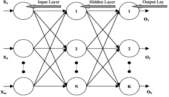
used for determining the injected voltage and voltage angle of UPFC. The UPFC injected voltage and voltage angle are determined based on the optimal generation limits of the generators. The feed forward network consists of three layers: input layer, hidden layer and output layer. The input of
[image:7.595.151.448.199.369.2]the network is optimal generation limits of the generators and the output of the network is the injected voltage and voltage angle of each buses. The structure of feed forward network is illustrated in Figure 3.
Figure 3: Structure Of Feed Forward Neural Network
The inputs of the network are denoted asx1,x2and xm, the outputs of the network are denoted aso1,o2andok. The weights of the network from input layer to hidden layer is denoted as
pn nandV V V V
1 22
11, ,... respectively. Then, the weights between hidden and output layer is denoted as W11,W22,...W1nandWmprespectively. The network is trained by back propagation training algorithm. The back-propagation algorithm is one of the most famous algorithm to train a feed forward network [35]. The back propagation training algorithm is divided into two phases that
are named as propagation and weight update. The network training steps are described as following them,
Back propagation learning algorithm steps
(1) The input and hidden layer, hidden and output layer weights of the neural network are initialized randomly.
(2) Learning the network according to the input and the corresponding target.
(3) Calculate the back propagation error of the targeto1,o2andok.
) ( 1 ) ( 1
1 NN tar NN out
error o o
BP = −
) ( 2 ) ( 2
2 NN tar NNout
error o o
BP = −
(18)
) ( )
( NN out
k tar NN k k
error o o
BP = −
Where,
o
kNN(tar)is the network target of the thk
node and NN(out) ko is the current output of the network.
(4) The current output of the network is determined by following them,
∑
=+ =
N
n
NN n out
NN
n o w o
1 1 1 1 ) (
1 α ( )
∑
= + =N
n
NN n out
NN
n o w o
1 2
2 2 ) (
2 α ( ) (19)
∑
= + =N
n
NN k kn k
out NN
k w o n
o
1 )
Where,α1,
2
α
andk
α
arethe bias function of the node1
,
2
and
k
respectively.) exp(
1
1 )
(
2 2 1 1
1 w o w o
n o
n n NN
− − + =
) exp(
1
1 )
(
2 2
2 n kn k
NN
o w o w n
o
− − +
= (20)
) exp(
1
1 )
(
1 1 o w o w n
o
n k kn NN
k
− − + =
(5) The new weights of the each neurons of the network are update by
w
w
w
oldnew
=
+
∆
. Here,w
new isthe new weight, wold is the previous weight and
∆
w
is the change of weight of each output. The change of weight is determined by follow,1 1 1 . .
error
BP o w =δ
∆
2 2 2 .o .BPerror w =δ
∆ (21) k
error k
k o BP
w =δ. . ∆
Where, δis the learning rate (0.2 to 0.5).
(6) Repeat the above steps till the BPerrorgets
minimized BPerror<0.1.
Once the neural network training process is completed, the network is trained well for identifying the injected voltage and voltage angle of the input. Based on the output of the network, the UPFC voltage and voltage angle is injected. After connecting the UPFC, the load flow analysis applied. Here, the Newton Raphson load flow algorithm used for analyzing the power flow solution [36]. Then, the fuel cost, emission, UPFC installation cost and power loss are determined.
4. RESULTS AND DISCUSSION
Figure 4: Line Diagram Of IEEE 30 Bus System.
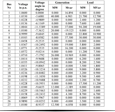
Table 1: Bus Data For IEE 30 Bus System.
Bus No
Voltage in p.u.
Voltage angle in degree
Generation Load
MW Mvar MW MVar
28 1.0094 -7.6744 0.000 0.000 0.000 0.000 29 0.9899 -10.1968 0.000 0.000 2.400 0.900 30 0.9782 -11.1042 0.000 0.000 10.600 1.900
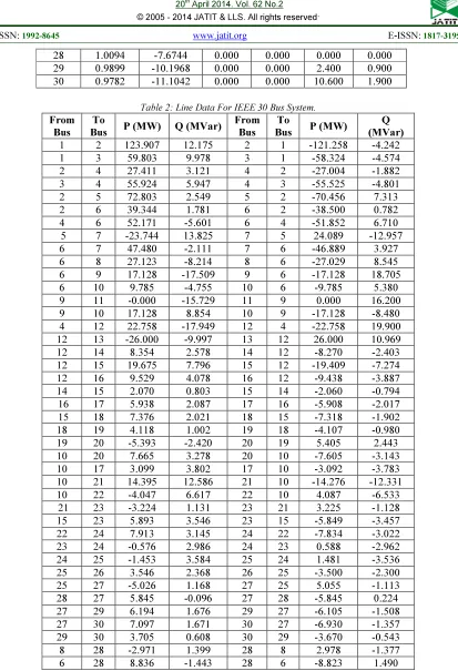
Table 2: Line Data For IEEE 30 Bus System. From
Bus To
Bus P (MW) Q (MVar)
From Bus
To
Bus P (MW)
Q (MVar) 1 2 123.907 12.175 2 1 -121.258 -4.242 1 3 59.803 9.978 3 1 -58.324 -4.574 2 4 27.411 3.121 4 2 -27.004 -1.882 3 4 55.924 5.947 4 3 -55.525 -4.801 2 5 72.803 2.549 5 2 -70.456 7.313 2 6 39.344 1.781 6 2 -38.500 0.782 4 6 52.171 -5.601 6 4 -51.852 6.710 5 7 -23.744 13.825 7 5 24.089 -12.957 6 7 47.480 -2.111 7 6 -46.889 3.927 6 8 27.123 -8.214 8 6 -27.029 8.545 6 9 17.128 -17.509 9 6 -17.128 18.705 6 10 9.785 -4.755 10 6 -9.785 5.380 9 11 -0.000 -15.729 11 9 0.000 16.200 9 10 17.128 8.854 10 9 -17.128 -8.480 4 12 22.758 -17.949 12 4 -22.758 19.900 12 13 -26.000 -9.997 13 12 26.000 10.969 12 14 8.354 2.578 14 12 -8.270 -2.403 12 15 19.675 7.796 15 12 -19.409 -7.274 12 16 9.529 4.078 16 12 -9.438 -3.887 14 15 2.070 0.803 15 14 -2.060 -0.794 16 17 5.938 2.087 17 16 -5.908 -2.017 15 18 7.376 2.021 18 15 -7.318 -1.902 18 19 4.118 1.002 19 18 -4.107 -0.980 19 20 -5.393 -2.420 20 19 5.405 2.443 10 20 7.665 3.278 20 10 -7.605 -3.143 10 17 3.099 3.802 17 10 -3.092 -3.783 10 21 14.395 12.586 21 10 -14.276 -12.331 10 22 -4.047 6.617 22 10 4.087 -6.533 21 23 -3.224 1.131 23 21 3.225 -1.128 15 23 5.893 3.546 23 15 -5.849 -3.457 22 24 7.913 3.145 24 22 -7.834 -3.022 23 24 -0.576 2.986 24 23 0.588 -2.962 24 25 -1.453 3.584 25 24 1.481 -3.536 25 26 3.546 2.368 26 25 -3.500 -2.300 25 27 -5.026 1.168 27 25 5.055 -1.113 28 27 5.845 -0.096 27 28 -5.845 0.224 27 29 6.194 1.676 29 27 -6.105 -1.508 27 30 7.097 1.671 30 27 -6.930 -1.357 29 30 3.705 0.608 30 29 -3.670 -0.543 8 28 -2.971 1.399 28 8 2.978 -1.377 6 28 8.836 -1.443 28 6 -8.823 1.490
The power loss of IEEE 30 bus system is 10.809 MW which determined by applying the power flow solution. Then, based on the above described data set, the optimal power flow concept of proposed
algorithm. The optimal generation limits are determined by based on the objective function of fuel cost, emission and power losses. The fuel cost and the emission coefficient of the generator bus are tabulated in Table 3. Then, the total generation
[image:11.595.127.470.201.306.2]real power limit is applied to the input of neural network. The output of the network is the injected voltage, voltage angle of all the buses of the system.
Table 3: Fuel Cost And Emission Coefficient. Generator
bus number
Fuel cost coefficient Emission coefficient
i
a bi ci αi βi
i
γ
1 0 2 0.0038 0.0126 -1.1 22.983 2 0 1.75 0.0175 0.02 -0.1 25.313 6 0 1 0.0625 0.027 -0.01 25.505 13 0 3.25 0.0083 0.0291 -0.005 24.9
22 0 3 0.025 0.029 -0.004 24.7
27 0 3 0.025 0.0271 -0.00055 25.3
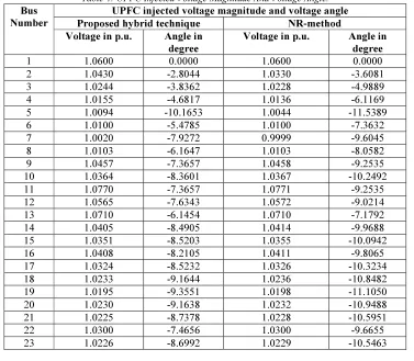
From the output of neural network, the UPFC injected voltage magnitude and voltage angle are obtained. The obtained voltage magnitude and voltage angle are compared with ABC algorithm. The compared values are tabulated in Table 4. Then, the UPFC is connected at different buses and the power loss, UPFC installation cost, fuel cost and emission are determined. The UPFC connected
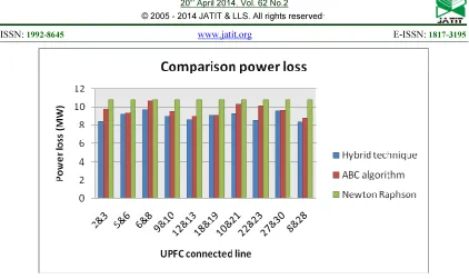
buses and the corresponding power loss, cost base parameters and emission of the tested system are tabulated in Table 5. The loss comparison charts of proposed hybrid technique and ABC algorithm are described in Figure 6. The cost comparison performance of hybrid technique and ABC algorithm is illustrated in Figure 7.
Table 4: UPFC Injected Voltage Magnitude And Voltage Angle. Bus
Number
UPFC injected voltage magnitude and voltage angle Proposed hybrid technique NR-method Voltage in p.u. Angle in
degree
Voltage in p.u. Angle in degree
1 1.0600 0.0000 1.0600 0.0000
2 1.0430 -2.8044 1.0330 -3.6081
3 1.0244 -3.8362 1.0228 -4.9889
4 1.0155 -4.6817 1.0136 -6.1169
5 1.0094 -10.1653 1.0044 -11.5389
6 1.0100 -5.4785 1.0100 -7.3632
7 1.0020 -7.9272 0.9999 -9.6045
8 1.0103 -6.1647 1.0103 -8.0582
9 1.0457 -7.3657 1.0458 -9.2535
10 1.0364 -8.3601 1.0367 -10.2492
11 1.0770 -7.3657 1.0771 -9.2535
12 1.0565 -7.6343 1.0572 -9.0214
13 1.0710 -6.1454 1.0710 -7.1792
14 1.0405 -8.4905 1.0414 -9.9688
15 1.0351 -8.5203 1.0355 -10.0942
16 1.0408 -8.2105 1.0411 -9.8065
17 1.0324 -8.5232 1.0326 -10.3234
18 1.0233 -9.1644 1.0236 -10.8482
19 1.0195 -9.3551 1.0198 -11.1050
20 1.0230 -9.1638 1.0232 -10.9488
21 1.0225 -8.7378 1.0228 -10.5951
22 1.0300 -7.4656 1.0300 -9.6655
[image:11.595.111.488.423.752.2]24 1.0155 -8.1414 1.0158 -10.2432
25 1.0068 -7.3492 1.0069 -9.5967
26 0.9889 -7.7779 0.9890 -10.0252
27 1.0100 -6.5952 1.0100 -8.9337
28 1.0096 -5.7390 1.0094 -7.6744
29 0.9899 -7.8583 0.9899 -10.1968
[image:12.595.93.510.79.611.2]30 0.9782 -8.7657 0.9782 -11.1042
Table 5: The Power Loss, UPFC Installation Cost, Fuel Cost And Emission UPFC
connected bus
Power loss of proposed
method
UPFC installation cost ($/KVar)
Fuel cost ($/hr)
Emission (Kg/hr)
2-3 8.4197 185.6821 723.4103 309.2178 5-6 9.1681 184.4326 497.4753 207.7048 6-8 9.6427 189.8293 709.3847 305.2213 9-10 8.9303 185.6462 622.8654 243.4336 12-13 8.6038 185.3133 597.209 250.5799 18-19 9.0287 185.9104 670.7175 284.8097 10-21 9.2015 185.9531 702.2233 291.0308 22-23 8.5548 187.0827 743.3521 329.4189 27-30 9.5826 187.9167 509.228 208.6349 8-28 8.375 190.2497 676.3555 282.9007
Figure 7: Power Loss Comparison
The Table 4 and 5 shows that, the performance of proposed hybrid technique. For evaluating the performance of proposed technique, it compared with the ABC algorithm and Newton-Raphson method. In table 4, the UPFC injected voltage magnitude and voltage angle of proposed hybrid technique are compared with ABC algorithm. From the comparative analysis, the proposed hybrid technique is selected the injected angle optimally when compared to ABC algorithm. So, the power loss of the proposed method is reduced as well as the fuel cost and emissions are reduced. As, the proposed hybrid technique is achieved a remarkable level for maintaining optimal power flow in power system. Then, the average fuel cost of proposed method is compared with existed work in literature which is presented in table 6. In table 6, the fuel cost of proposed method (with UPFC) is compared with GSA, PSO, BBO, MDE, ABC, and DE without using UPFC device. From the comparative analysis, the proposed method give the fuel cost averagely 645.22 $/hr. But the fuel costs of the existed works are higher as considerable level to the proposed method.
Table 6: Comparison Of Fuel Cost Methods Fuel cost ($/hr) Proposed method with UPFC 645.22
GSA without UPFC [37] 646.84806 PSO without UPFC [38] 647.69 BBO without UPFC [39] 647.7437 MDE without UPFC [40] 647.846
ABC without UPFC [41] 649.0855 DE without UPFC [42] 650.8224
5. CONCLUSION
In the paper, the hybrid OPF technique with FACTS controller was proposed. Then, the proposed hybrid technique was implemented and the OPF performance was tested with IEEE 30 bus system. The optimal generation limits were determined by ABC algorithm and the fuel cost, emission and power loss were analyzed. Then, the analyzed hybrid technique results were compared with ABC algorithm. From the comparative analysis, the proposed hybrid technique has less fuel cost, emission and power loss. Also, the UPFC injected voltage magnitude and the voltage angle are calculated best possible values when compared to ABC algorithm. Since, the voltage deviation is reduced, the real power loss of the system is also reduced. Thus, the power variations of the buses are controlled and the UPFC installation cost is maintained economically. Since, the proposed hybrid technique maintained the OPF concept optimally when compared to ABC algorithm.
REFERENCES
[1] D. Murali, Dr. M.Rajaram and N.Reka, ”Comparison of FACTS Devices for Power System Stability Enhancement “, International Journal of Computer Applications, Vol. 8, No.4 2010.
International Journal of Electrical Power and Energy Systems, No.25, pp. 533–541, 2003. [3] M.A. Abido, ”Optimal Power Flow Using
Tabu Search Algorithm”, International Journal of Electric Power Components and Systems, Vol.30, pp.469-483, 2002.
[4] Priyanka Roy and Chakarabarti, ”Genetic algorithm based optimal power flow solution for determination of spot pricing of generators in deregulated electricity environment of a developing country”, Journal of Acta Electrotehnica, Vol.53, No.1, 2012.
[5] Luonan Chen , Hideki Suzuki and Kazuo Katou, ” Mean field Theroy for optimal Power Flow”, IEEE transaction on Power Systems, Vol.12, No.4, Nov 1997.
[6] Ajit Gopalakrishnan, Arvind U. Raghunathan, Daniel Nikovski and Lorenz T.Biegler, ”Global Optimization of Optimal Power Flow using a Branch & Bound Algorithm”, In Proceedings of 50th Annual Allerton Conference on
Communication, Control, and Computing,
Champaign, IL, USA October, 2012.
[7] Sourav Mallick, D.V. Rajan, S.S. Thakur, P. Acharjee and S.P. Ghoshal, “Development of a new algorithm for power flow analysis”, International Journal of Electrical Power and Energy Systems, Vol. 33, pp.1479–1488, 2011. [8] Martin Geidl and Göran Andersson, ”Optimal
Power Flow of Multiple Energy Carriers”, IEEE Transactions On Power Systems, Vol. 22, No.1, 2007.
[9] S. Sivasubramani and K. S. Swarup, “Multiagent based particle swarm optimization approach to economic dispatch with security constraints,” in International Conference on Power Systems, 2009.
[10]Edilaine Martins Soler, Vanusa Alves de Sousa and Geraldo R.M. da Costa, “A modified Primal–Dual Logarithmic-Barrier Method for solving the Optimal Power Flow problem with discrete and continuous control variables”, European Journal of Operational Research, Vol. 222, pp.616–622, 2012.
[11]C-T Liu and T-S Yeh, ”Parallel simulation of industrial power system transients by an inherent parallel algorithm”, International Journal of Electrical Power and Energy Systems, Vol. 18, No. 7, pp. 437-443, 1996. [12]Xiaoyu Yang, Xiaoxin Zhou, Yichen Ma and
Zhengchun Du, “Asymptotic numerical method for continuation power flow”, International Journal of Electrical Power and Energy Systems, Vol.43, pp. 670–679, 2012
[13]Yog Raj Sood, ”Evolutionary programming based optimal power flow and its validation for deregulated power system analysis”, International Journal of Electrical Power and Energy Systems, Vol.29, pp.65-75, 2007. [14]Javad Lavaei and Steven H. Low,
”Convexification of Optimal Power Flow Problem”, In Proceedings of conference on OPF, 2010.
[15]Dennice Gayme and Ufuk Topcu,”Optimal power flow with distributed energy storage dynamics”, In Proceedings of American Control Conference, 2011.
[16]Hassan Kubba and Hazlie Mokhlis, “An enhanced RCGA for a rapid and reliable load flow solution of electrical power systems”, International Journal of Electrical Power and Energy Systems, Vol.43, pp.304–312, 2012. [17]K. Shanmukha Sundar and H.M. Ravikumar,
“Selection of TCSC location for secured optimal power flow under normal and network contingencies”, International Journal of Electrical Power and Energy Systems, Vol.34, pp.29–37, 2012.
[18]Mahdad, K. Srairi and T. Bouktir, ”Optimal power flow for large-scale power system with shunt FACTS using efficient parallel GA”, International Journal of Electrical Power and Energy Systems , Vol.32 , pp.507–517, 2010. [19]Keyan Liu, Yunhua Li and Wanxing Sheng,
”The decomposition and computation method for distributed optimal power flow based on message passing interface (MPI)”, International Journal of Electrical Power and Energy Systems, Vol.33, pp. 1185-1193, 2011. [20]M. Basu, ”Optimal Power flow with FACTS devices using differential evolution”, Journal of Electrical Power and Energy Systems, Vol.30, No.2, pp.150-156, 2008.
[21]S. Sivasubramani and K.S. Swarup, “Multi-objective harmony search algorithm for optimal power flow problem”, International Journal of Electrical Power and Energy Systems, Vol. 33, pp.745–752, 2011.
[22]Shieh-Shing Lin, Shih-Cheng Horng and Chi-Hsin Lin, “Embedding sensitivity theory in ordinal optimization for decentralized optimal power flow control”, International journal of Electrical Power and Energy Systems, Vol. 34, pp.145–153, 2012.
Power and Energy Systems, Vol. 42, pp.614– 620, 2012.
[24]L.E.S. Pereira, V.M. da Costa and A.L.S. Rosa, “Interval arithmetic in current injection power flow analysis”, International Journal of Electrical Power and Energy Systems, Vol. 43 pp.1106–1113, 2012.
[25]Xiaoqing Bai and Hua Wei, “A semi definite programming method with graph partitioning technique for optimal power flow problems”, International Journal of Electrical Power and Energy Systems, Vol.33, pp.1309–1314, 2011. [26]Lashkar Ara, A., Kazemi, A., and Nabavi
Niaki, S.A., "Multiobjective Optimal Location of FACTS Shunt-Series Controllers for Power System Operation Planning", IEEE Transactions on Power Delivery, Vol.27, No.2, pp,481-490, 2012.
[27]A. V. Naresh Babu and S. Sivanagaraju, "A New Approach for Optimal Power Flow Solution Based on Two Step Initialization with Multi-Line FACTS Device", International Journal on Electrical Engineerin g and Informatics, Vol.4, No.1, pp.173-185, 2012.
[28]Arup Ratan Bhowmik, and Champa Nandi, "Implementation of Unified Power Flow Controller (UPFC) for Power Quality Improvement in IEEE 14-Bus System", Int. J. Comp. Tech. Appl., Vol.2, No.6, pp.1889-1896, 2011
[29]Satakshi Singh, "The Unified Power Flow Controller Optimal Power Flow Model",
International Journal of Scientific and
Research Publications, Vol.2, No.8, pp.1-3, August 2012
[30]Schauder, C.D., Gyugyi, L., Lund, M.R., Hamai, D.M., Rietman, T.R., Torgerson, D.R., and Edris, A., "Operation of the unified power flow controller (UPFC) under practical constraints", IEEE Transactions on Power Delivery, Vol.13, No.2, pp.630-639, 1998 [31]Wanliang Fang, and H.W. Ngan, "A robust
load flow technique for use in power systems with unified power flow controllers", Electric
Power Systems Research, Vol.53, No.3,
pp.181-186, 200
[32]Adil Baykasoulu, Lale Ozbakir, and Pinar Tapkan, "Artificial Bee Colony Algorithm and Its Application to Generalized Assignment Problem", Itech Education and Publishing, 2007
[33]Dervis Karaboga and Bahriye Basturk, "Artificial Bee Colony (ABC) Optimization Algorithm for Solving Constrained Optimization Problems", World Congress on Foundations of Fuzzy Logic and Soft
Computing, pp.789-798, 2007
[34]D. Micusik, V. Stopjakova and L. Benuskova, "Application of Feed-forward Artificial Neural Networks to the Identification of Defective Analog Integrated Circuits", Neural Computing and Applications, Vol.11, pp.71-79, 2002 [35]Sudarshan Nandy, Partha Pratim Sarkar, and
Achintya Das, "Training A Feed-Forward Neural Network With Artificial Bee Colony Based Back Propagation Method", International Journal of Computer Science & Information Technology (IJCSIT), Vol.4, No.4, pp.33-46, August 201
[36]Samina Elyas Mubeen, R. K. Nema, and Gayatri Agnihotri, "Power Flow Control with UPFC in Power Transmission System", World
Academy of Science, Engineering and
Technology, Vol.23, pp.338-342, 2008 [37]Duman S, Guvenc U, Sonmez Y, and
Yorukeren N, "Optimal power flow using gravitational search algorithm" Energy Conversion and Management, Vol.59, pp.86– 95, 2012
[38]Abido MA, "Optimal power flow using particle swarm optimization", International Journal of Electrical Power & Energy Systems, Vol.24, No.7563–7571, 2002
[39]Bhattacharya A, and Chattopadhyay, "Application of biogeography-based optimization to solve different optimal power flow problems", IET Generation, Transmission & Distribution, Vol.5, No.1, pp.70–80, 2011 [40]Sayah S, and Zehar Kh., "Modified differential
evolution algorithm for optimal power flow with non-smooth cost function" Energy
Conversion and Management, Vol.49,
pp.3036-3042, 2008
[41]M. Rezaei Adaryani, and A. Karami, "Artificial bee colony algorithm for solving multi-objective optimal power flow problem", Electrical Power and Energy Systems, Vol.53, pp.219–230, 2013