A Review on Enhancing the Performance of MPPT
for Single Stage PV-Grid Connected System Using
Particle Swarm Optimization Technique
Ms. Trivelli Shekhar Naidu1, Prof. Bushra Khan2, Prof. Radharaman Shah3
1,2,3,Department of Electrical Engineering (IPS),Abha Gaikwad Patil College of Engineering, RTMNU
Abstract: The scaling of maximum power point tracking (MPPT) system is suggested. The optimal operating point of a solar module is known as the maximum power point (MPP) and it changes with its own characteristic as well as cell temperature and sunlight. The scaling S-PVMPPT algorithm is modified algorithm to achieve MPPT in spite of single or 80 micro-meter up to 4 decimal places, that is, an error no bigger than 10−4 , the Trapezoidal Rule, we could take big enough so that 1/n2 ≤ 10−4 solar
PV cells. The most important rule, in practice, is the Simpson’s Rule, because of its simplicity and accuracy. From the simulation and experimental results, the particle swarm optimization (PSO) based maximum power point tracking (MPPT) for PV system is presented which is interrelated with other control schemes such as synchronization with grid and current control finding lower error event as compare with PV-MPPT with same saturated voltage and it can deliver more power than the conventional MPPT Technique.
Keywords— Maximum Power Point Tracking (MPPT), Photovoltaic (PV), Particle Swarm Optimization (PSO), Trapezoidal
rule, Simpson’s rule
I. INTRODUCTION
The voltage-power specific of a photovoltaic (PV) array is nonlinear and time varying because of the changes caused by the atmospheric conditions. The task of a Maximum Power Point (MPP) Tracking (MPPT) in a PV power system is to constantly tune the system so that it draws maximum power from the PV array. In current years, the Simpson-PVMPPT systems have developed more popular because they do not need battery backups to ensure MPPT. The two typical outlines of a Simpson-PV-MPPT system are single or two stages. In two stages, the first is used to boost the PV array voltage and track the maximum power; the second permits the adaptation of this power into high-quality AC voltage. The incidence of numerous power phases undermines the overall efficiency, reliability, and compactness of the system besides increasing the cost. The single stage has frequent, advantages, such as simple topology, high efficiency, etc. Nevertheless, the control strategy has to be calculated in order to remove the maximum available power and to properly transfer it from the PV array to the grid simultaneously. In this case, an important consideration in the controller design is needed.
II. SOLAR CELL AND PV ARRAY MODULE
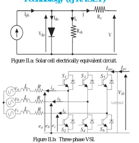
PV generator is a combination of solar cells, connections, protective parts, supports, etc. In the present modelling, the focus is only on cells. Solar cells consist of a p-n junction; various modelling of solar cells have been proposed in the literature [14]–[16]. Thus, the simplest equivalent circuit of a solar cell is a current source in parallel with a diode. The output of the current source is directly proportional to the light falling on the cell (photocurrent). During darkness, the solar cell is not an active device; it works as a diode, i.e., a p-n junction. It produces neither a current nor a voltage. Thus, the diode determines the I–V characteristics of the cell. For this paper, the electrical equivalent circuit of a solar cell is shown in Figure 1 The output current I and the output voltage of a solar cell are given by
Figure II.a: Solar cell electrically equivalent circuit.
Figure II.b: Three-phase VSI.
the Boltzmann’s constant (k = 1.38∗10−23), and T is the solar array panel temperature. R
sis the intrinsic series resistance of the solar
cell; this value is normally very small. Rsh is the equivalent shunt resistance of the solar array, and its value is very large. In general,
the output current of a solar cell is expressed by
---(4) In (4), the resistances can be generally neglected, and thus, it can be simplified to
---(5) If the circuit is opened, the output current I = 0, and the open-circuit voltage Voc is expressed by
---(6)
If the circuit is shorted, the output voltage V = 0, the average current through the diode is generally neglected, and the short circuit current Isc is expressed by using
---(7) Finally, the output power P is expressed by
---(8)
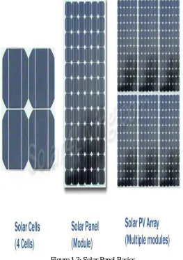
Figure 1.3: Solar Panel Basics
PV Cell: The smallest, basic photovoltaic device that converts radiation directly into electricity. Each PV cell is rated for 0.5 0.7 volt and a current of 30mA/cm2. Based on the manufacturing process they are classified as:
Mono crystalline: efficiency of 12-14 %. These are now predominantly available in Market Poly crystalline: efficiency of 12%
Amorphous: efficiency of 6-8%
Life of crystalline cells is in the range of 25 years where as for amorphous cells it is in the range of 5 years. PV Module: Series and parallel connected solar cells (normally of 36Wp rating).
PV Array: Series and parallel connected PV modules (generally consisting of 5 Modules).
III.PROPOSED WORK
Here, f = frequency 10 kHz. The inductance and capacitance are calculated as L = 100 µH, C = 220 µF.
Most of the cases the requirement of load voltage is greater than source voltage, because long series strings in SPVA may result in more power loss under partial shaded conditions.
An alternative and effective solution is provided by particle swarm optimization (PSO) based method which has fast computational capability and easy to implement due to its simple structure. In [11], the conventional PSO is implemented for MPPT with various extra coefficients, thus, the computational burden of the algorithm is increased.
Moreover, most of the PSO algorithms presented in previous works have been implemented and tested for two-stage PV system where the duty ratios are selected as PSO agents. This paper proposes a simple PSO based MPPT algorithm for a single-stage photovoltaic system, which is operated with other control. It is found that the modified PSO method tracks the MPP with fast speed and good accuracy.
The purpose of MPPT is to track the maximum power point (MPP) of PV characteristics, irrespective of variation in atmospheric conditions. In this paper, particle swarm optimization method is utilized for this purpose. The output of the MPPT controller gives the reference value (vdcref) for dc link voltage controller. PSO was developed by Eberhart and Kennedy in 1995 [15-16] inspired by
social behavior of birds flocking or fish schooling. It is a meta-heuristic, population-based intelligence method that can be applied to optimization problem to search the optimal point. Particle Swarm has two primary operators: velocity update and position update. In each iteration each particle is accelerated toward the particle’s previous best position (pbest) and the global best position (gbest).In
each iteration a new velocity value for each particle is calculated based on its current velocity, the distance from its previous best position, and from the global best position. The new velocity value is, then, used to calculate the next position of the particle in the search space. This process is, then, iterated a set number of times or until a minimum error is achieved. By this process, all particles reach to a global optimal solution.
These points are expressed by the following equations which define the standard PSO method:
where, siand λiare the position and velocity of ithparticle respectively; k denotes the iteration number; w is the inertia weight; r1and r2are random variables uniformly distributed within [0, 1] ;c1 and c2 are the acceleration coefficients; pbest, Iis used to store the best
position of ithparticle found so far and g
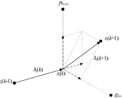
best is the best position of all particles in the entire population. The trajectory of typical
particle movement for one iteration cycle is shown in Fig. 6. The positions of particles are adjusted if the following condition is satisfied:
where, f is the fitness value evaluation function (objective function) which is maximized in each iteration cycle till all the particles evolve to the optimal solution.
For MPPT, the position is defined as PV voltage (vPV) and the velocity is the perturbation in the reference voltage for the dc-link
voltage controller. The solution vector of PV voltage (vPV) with N particles is defined as
Figure 6.1: Particle movement trajectory in PSO search method
IV.CONCLUSIONS
The electricity sector have many quandary regarding, the supply of electricity, so renewable energy advancement policies have increase the solar energy consumption. The consequential of photovoltaic cell connected to the grids. This work propose the single stage inverter with maximum power point tracking (MPPT) and one cycle controlled (OCC) for grid connected PV system. One cycle controlled scheme is predicated on the output current adjustment .Schemes predicated on one-cycle control (OCC) which do not require the accommodation of a phase locked loop for interfacing the inverter to the grid are increasingly being employed for such applications. It requires less no. of sensors (two) as compared to that required (four) in the earlier reported scheme for the implementation of the core controller comprising of OCC and MPPT blocks.
V. ACKNOWLEDGMENT
We wish to acknowledge Michael Shell and other contributors for developing and maintaining the IEEE LaTeX style files which have been used in the preparation of this template. The other Contributors are mentioned in the references.
REFERENCES
[1] O. Ibidapo-Obe, O.O.E. Ajibola, Towards a Renewable Energy Development for Rural Power Sufficiency. International Conference on Innovations in Engineering and Technology. (2011)
[2] O.I. Okoro, and E. Chikuni, Power sector reforms in Nigeria: opportunities and challenges. Journal of Energy in Southern Africa, vol.18, No. 3, pp.52-57 (2007)
[3] Yankari-Reports: FG urges Nigerians to explore renewable energy for positive development. http://yankarireports.com/fg-urges-nigerians-to-explore-renewable-energy-forpositive-development/ (2013)Accessed 21 June, 2013.
[4] C. Meza, J. J. Negroni, D. Biel, and F. Guinjoan, ―Energy-balance modeling and discrete control for single-phase grid-connected PV central inverters,‖ IEEE
Trans. Ind. Electron., vol. 55, no. 7, pp. 2734–2743, Jul. 2008.
[5] Trends in Photovoltaic Application, Survey Report of Selected IEA Countries Between 1992 and 2002 International Energy Agency Pho-tovoltaic Power System, IEA, Pvps t1-12:2003, 2003 -
[6] K. Hemmes, ―Towards multi-source multi-product and other integrated energy systems,‖ Int. J. Integr. Energy Syst., vol. 1, no. 1, pp. 1–15, Jan.–Jun. 2009. [7] F. Liu, Y. Zhou, S. Duan, J. Yin, B. Liu, and F. Liu, ―Parameter design of a two-current-loop controller used in a grid-connected inverter system with LCL
filter,‖ IEEE Trans. Ind. Electron., vol. 56, no. 11, pp. 4483–4491, Nov. 2009.
[8] Azevedo, G.M.S., Cavalcanti, M.C., Oliveira, K.C., Neves, F.A.S. and Lins, Z.D., “Evaluation of maximum power point tracking methods for grid connected photovoltaic systems,” Conference on Power Electronics Specialists, 2008. PESC 2008. IEEE , August 2008, pp. 1456 - 1462.
[9] Kjaer, S.B., Pedersen, J.K. and Blaabjerg, F., “A Review of single-phase grid connected inverters for photovoltaic modules,” Industry Applications, IEEE Transactions , vol. 41, September 2005, pp.1292-1306.
[10] N. Femia, G. Petrone, G. Spagnuolo, andM. Vitelli, ―Optimization of perturb and observe maximum power point tracking method, IEEE Trans. Power
Electron., vol. 20, no. 4, pp. 963–973, Jul. 2005.
[16] A. F. Williams, The Handbook of Photovoltaic Applications: Building Applications and System Design Considerations. Atlanta, GA: FairmontPress, 1986. [17] Dhople, S.V., Davoudi, A. and Chapman, P.L., “Dual stage Converter to improve transfer efficiency and maximum power point tracking feasibility in
photovoltaic energy-conversion systems,” Applied Power Electronics Conference and Exposition (APEC), 2010 Twenty-Fifth Annual IEEE, March 2010, pp. 2138 - 2142.
[18] Kasa N, Iida T, Chen L. Flyback inverter controlled by Sensorless current MPPT for photovoltaic power system. IEEE Trans Ind Electron 2005;52(4):1145– 52.