International Journal of Emerging Technology and Advanced Engineering
Website: www.ijetae.com (ISSN 2250-2459,ISO 9001:2008 Certified Journal, Volume 5, Issue 5, May 2015)
131
Analysis and Optimization of Compressor Mounting Plate of
Refrigerator using FEA
Pushpendra Mahajan
1, Prof. Abhijit L. Dandavate
21
Student, ME-Mechanical Design First Year, Dhole Patil College of Engineering, Wagholi, Pune- 412207 (India) 2
Head of Department, Mechanical Engineering Department, Dhole Patil College of Engineering, Wagholi, Pune, India
Abstract— NVH is one of the major factors impacting quality for household appliances like refrigerators. In refrigerators, compressor is the main source for vibrations and noise. Compressor is attached to compressor mounting plate which is then attached to refrigerator body. Compressor being dynamic component also exerts harmonic exiting forces on the mounting plate. If compressor operating frequency matches with natural frequency of plate then resonance would occur leading to excessive vibrations and noise. Hence the plate should have natural frequency beyond the operating range of compressor. In this paper, natural frequency and static state deflection of a compressor mounting plate are analyzed using FEA software, Ansys. Further two methods of improving and optimizing the design to increase the natural frequency are illustrated and analyzed.
Keywords— Compressor Mounting Plate, Analysis, Optimization, FEM, FEA, Natural Frequency.
I. INTRODUCTION
Compressor is the main functional component in the refrigeration cycle. Compressor is assembled on the compressor mounting plate. This subassembly is then assembled on the refrigerator body in the rear bottom side of refrigerator. In the existing design compressor mounting plate is assembled on the refrigerator body using two fastener locations. Compressor being the dynamic component generates vibration and noise. Vibration is transferred to refrigerator body through mounting plate. During the operating cycle, compressor will also exert harmonic pulsating forces on the mounting plate. Frequency of these forces is the operating frequency of compressor (1500 RPM to 4500 RPM). If the frequency of exciting forces matches the natural frequency of the
material, resonance occurs. Resonance will be
characterized by excessive vibration amplitude and noise. Since refrigerator is a household appliance, any noticeable noise level increase from refrigerator leads to negative impact on perceived quality of the product and hence impacts sales. Further, noticeable noise level increase will also cause the customer to raise a service call and hence the company has to bear additional service cost
Compressor mounting plate is also very close to the floor of the house since it is present is bottom portion of refrigerator. Compressor considered has a weight of 12 Kg. Hence compressor mounting plate has to support this dead weight. Due to the weight, there will be some deformation in the plate. It is very important that this deformation is not excessive since plate will touch the floor in case of excessive deformation.
Thus the compressor mounting plate has two main functions:
1. To minimize vibrations and prevent resonance in any case
2. To minimize static deformation
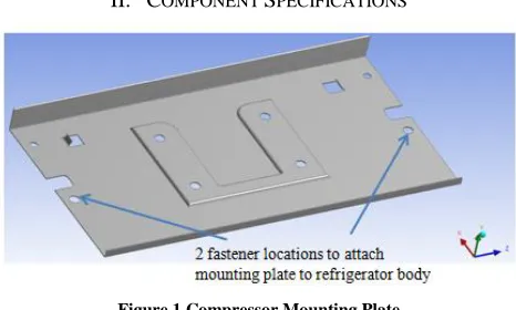
[image:1.612.327.560.404.544.2]II. COMPONENT SPECIFICATIONS
Figure 1 Compressor Mounting Plate
Component analyzed: Compressor mounting plate Material: Structural steel
Material thickness: 1 mm Young’s Modulus: 200 GpA Yield Stress: 250 Mpa
Compressor operating speeds: 1500 RPM to 4500 RPM Compressor weight: 12 Kg
International Journal of Emerging Technology and Advanced Engineering
Website: www.ijetae.com (ISSN 2250-2459,ISO 9001:2008 Certified Journal, Volume 5, Issue 5, May 2015)
132
III. LITERATURE REVIEW
S. S. Rao [1] states that it is possible to reduce but not eliminate the dynamic forces that cause vibrations. Several methods can be used to control vibration. One of the methods is controlling the natural frequencies of the system and avoiding resonance under external excitation. He further states that most prominent feature of resonance is large displacement. In most mechanical and structural systems, large displacement indicates undesirably large strains and stresses, which can lead to failure of system. Hence resonance must be avoided. In most cases, excitation frequency cannot be controlled, because it is imposed by functional requirements of the system or machine. We must concentrate on controlling natural frequency of the system to avoid resonance. Natural frequency of the system can be changed by either varying mass m or the stiffness k. In many practical cases, mass cannot be changed easily, since its value is determined by functional requirement of the system. Therefore stiffness of the system is the factor that is most often changed to alter its natural frequency. Stiffness of shaft can be altered by varying one or more of its parameters such as material or the number and location of support points.
K.S.Kong [2] states that to avoid resonance, compressor bracket natural frequency must be more than operating frequency range of compressor
IV. OBJECTIVE FORMULATION
Compressor operating range = 1500 RPM to 4500 RPM
= 25 Hz to 75 Hz
We thus have specification limits for natural frequency of mounting plate. In any case, natural frequency of compressor mounting plate should be greater than 75 Hz. In view of ground clearance of compressor mounting plate, specification limit for static state deflection is chosen as 2 mm.
Objective of this research work is to optimize the compressor mounting plate design in such a way that compressor mounting plate has following:
1. Natural frequency more than 75 Hz
2. Static state deflection less than 2 mm
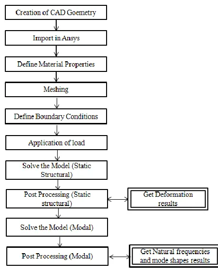
[image:2.612.331.556.154.438.2]V. FEM ANALYSIS OF EXISTING MOUNTING PLATE
Figure 2 Steps for FEM analysis using Ansys
A.
.
MeshingUniform quad mesh is generated using Ansys R13.0. Mesh element size of 5 mm is chosen.
[image:2.612.344.544.500.613.2]International Journal of Emerging Technology and Advanced Engineering
Website: www.ijetae.com (ISSN 2250-2459,ISO 9001:2008 Certified Journal, Volume 5, Issue 5, May 2015)
133
B. Boundary Conditions and Loads
Fixed boundary condition is applied at two fastener location of plate.
Total load (force) on plate = 12 x 9.81 = 117.7 N
Load is applied equally at four locations on compressor mounting plate.
[image:3.612.48.291.224.328.2]Load at each location = 117.7/4 = 30 N
Figure 4 Loads and Boundary Conditions
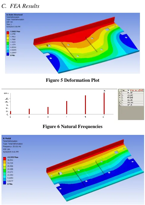
[image:3.612.46.290.349.694.2]C. FEA Results
[image:3.612.322.564.538.658.2]Figure 5 Deformation Plot
Figure 6 Natural Frequencies
Figure 7 Mode shape for lowest natural frequency
Thus following results are obtained from FEA analysis of existing base plate
Maximum Deformation = 2.5 mm Von Mises stress = 193 Mpa First Natural frequency = 25 Hz
Natural frequency is obtained through prestressed modal analysis
D. Results Interpretation
It is observed that static deformation of 2.5 mm is above the pre decided limit of 2 mm. Further natural frequency of 25 Hz matches with compressor operating range. Hence, this plate is bound to have resonance. In order to improve the results, following optimization work is done
VI. OPTIMIZATION APPROACH
From the literature review, it is clear that in order to increase natural frequency stiffness of component needs to be increased. Further, changing and increasing support is one of the methods observed to increase stiffness. The other method chosen is material thickness. Hence optimization is done based on following two approaches:
Approach 1: Increase and change support points (assembly locations for base plate)
Approach 2: Increase and optimize material thickness
VII. OPTIMIZATION BY APPROACH 1
Following iterations are performed to achieve the objectives decided.
Iteration 1: Increase the support points to 4 (one at each corner)
Iteration 2: Increase the support points to 5 (one at each corner and one at centre)
International Journal of Emerging Technology and Advanced Engineering
Website: www.ijetae.com (ISSN 2250-2459,ISO 9001:2008 Certified Journal, Volume 5, Issue 5, May 2015)
[image:4.612.50.284.122.555.2]134
Figure 9 Iteration 2 (5 assembly locations)
[image:4.612.49.290.132.263.2]A. FEA Results
TABLE I
FEA RESULTS APPROACH 1
[image:4.612.327.575.252.517.2]Figure 10 Trend Analysis of Results (Approach 1)
Figure 11 FEA Results with 5 support points (Iteration 2)
From the above results, it is observed that with five assembly locations for assembly of compressor mounting plate, deformation of 0.6 mm and natural frequency of 77 Hz is obtained. Thus both the objectives are met.
VIII. OPTIMIZATION BY APPROACH 2
It is observed that existing mounting plate has very low natural frequency (25 Hz). Hence it would require increasing material thickness by a large amount which is not feasible due to cost implications.
Hence iterations for material thickness are performed for compressor mounting plate with four support points (assembly locations).
Following iterations are performed for mounting plate with four support points:
Iteration 1: Material thickness of 1.1 mm Iteration 2: Material thickness of 1.2 mm Iteration 3: Material thickness of 1.3 mm
A. FEA Results
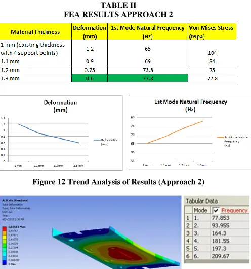
TABLE II
FEA RESULTS APPROACH 2
Figure 12 Trend Analysis of Results (Approach 2)
Figure 13 FEA Results with 1.3 mm material thickness (Iteration 3)
It is observed that with a material thickness of 1.3 mm and four support points, compressor mounting plate has a deformation of 0.6 mm and lowest natural frequency of 77.8 Hz. Thus, both the objectives are also met using this approach.
IX. CONCLUSION
Based on analysis and optimization work done, we conclude the following
[image:4.612.51.286.298.452.2] [image:4.612.52.288.472.561.2]International Journal of Emerging Technology and Advanced Engineering
Website: www.ijetae.com (ISSN 2250-2459,ISO 9001:2008 Certified Journal, Volume 5, Issue 5, May 2015)
135
2.In order to achieve static deformation less than 2 mm and natural frequency above 75 Hz, any of the following two solutions can be implemented:
Solution A: Provide 5 support points (assembly locations) for mounting plate Solution B: Provide 4 support points
(assembly locations) for mounting plate and increase material thickness to 1.3mm 3.Stress levels with 5 support points have increased as
compared to 4 support points. However stress level is still below yield point stress. Stress level decrease substantially with increasing material thickness 4.FEA Softwares (Ansys,etc) can be effectively used
for iterative product development and optimization
X. ASSUMPTIONS AND FUTURE SCOPE
A. Assumptions
1.Bolts/screws have not been considered for analysis 2.Effect of damping has not been considered for
calculation of natural frequencies
B. Future Scope
1.Exciting harmonic pulsating forces due to unbalanced rotating and reciprocating masses in compressor need to be calculated
2.Response of mounting plate to these pulsating forces can be analyzed. (Frequency response analysis) 3.Design of vibration isolation device for the system
(Elastomeric grommets)
XI. APPENDIX
A. Abbreviations and Acronyms
FEM – Finite Element Methods FEA – Finite Element Analysis NVH- Noise Vibration Harshness Hz – Hertz
RPM – Revolutions per minute
Acknowledgement
Authors wish to acknowledge Prof. Anantharama (Mechanical Department) from Dhole Patil College for additional guidance and the lab support from Dhole Patil College of Engineering, Pune
REFERENCES
[1] S.S. Rao, Fifth Edition, Prentice Hall Publication. Mechanical
Vibrations
[2] KS. Kong, 2013 Malaysia Altair Conference, ―Optimization driven
design of Compressor Mounting Bracket‖
[3] Sheshu P, PHI Learning Private limited, Textbook of Finite
Elements Analysis
[4] Vyankatesh D. Pawade, and Pushkraj D. Sonawane, International
journal of science and research, Volume 4, Issue 1, January 2015, ―Study of Design and analysis of air conditioner compressor mounting bracket‖
[5] Umesh S. Ghorpade, D.S. Chavan, Vinay Patil and Mahendra
Gaikwad, IJMIE, Volume 2, Issue 3, 2012, ―Finite Element Analysis and natural frequency optimization of Engine Bracket‖
[6] Tarundeep Singh Brar, Daljeet Singh, Journal of CAD CAM and
Robotics, Volume 2, Issue 3,2013, ―Dynamic Analysis of Compressor mounting bracket of automobile air conditioning system‖
[7] Jeong Woo Chang and Young Shin Lee, Journal of Mechanical