International Journal of Emerging Technology and Advanced Engineering
Website: www.ijetae.com (ISSN 2250-2459, ISO 9001:2008 Certified Journal, Volume 4, Issue 3, March 2014)
To Study the Paddle Feeder Operation with VFD and its Effect
on Conveyor Parameters
Niraj Kumar Sahu
1, Ram Prakash Bhatele
2 1Research Scholar, SVN University, Sagar (MP) India
2Principal, SRIT, Jabalpur (MP) India
Abstract— The aim of this paper is to study and analyze the performance parameters of conveyor, which is fed coal by the paddle feeders, with use of VFD in paddle feeder motors and comparison with other type of coupling used previously in paddle feeders. Paddle feeders are used in coal handling plant of a thermal power station to evacuate coal from track hoppers. In a track hopper conveyor two no. of paddle feeders are available of the 1250MT per hour coal evacuation capacity each. Initially the paddle feeders were operated with eddy current couplings, which were very much maintenance prone and costly due to that the same had been replaced with the fluid couplings. The fluid coupling has the fixed speed operation. Hence, the paddle feeders were operated at fixed speed and due to that the coal evacuation from a paddle feeder was fixed and there was no possibilities to run two nos. of paddle feeders at a time. Now by use of VFD in paddle feeders utilization of the conveyor has increased as two no. of paddle feeders are running at a time and running time of the system reduced. By the use of VFD in paddle feeder motor power consumption is less and same time the coal evacuation also increased.
Keywords—Coal Handling Plant, Eddy current coupling, Energy saving, Fluid coupling, Paddle feeder (PF), Variable frequency drive (VFD).
I. INTRODUCTION
Conveyors (as shown in fig.-1) are used in thermal power stations to transport the coal from track hopper (where coal is received from mines) to bunkers to use for generation of electricity. By increasing the utilization factor of conveyors the evacuation of coal from track hopper will be fast and running hour of the system will reduce and the same time energy saving will be there. Electricity is essential for growth and development of the industries. One have to put their sincere efforts to reduce the cost of generation of the electricity by taking corrective measures. One of the solutions for this is by reducing the auxiliary power consumption within the power station by increasing the utilization factor of the existing system adopting safe practices.Now a days thermal power stations are facing acute problem of coal supply used for generation. Also to reduce the cost of power generation the auxiliary power consumption & repair and maintenance cost of the plant should be reduced.
As a measure of cost reduction now a days VFDs[1] are used to run the auxiliary equipments (where there is a speed variation in equipments is required and which is being done by means of other methods of control) used for power generation in a thermal power plant to reduce the power consumption.
Fig.1 photograph of conveyor system
The Paddle Feeders feed the coal on the conveyor belt from the track hopper. The paddle blades projected in the hopper slot scoop the coal from hoppers and discharge it on the conveyor belt running below.
International Journal of Emerging Technology and Advanced Engineering
Website: www.ijetae.com (ISSN 2250-2459, ISO 9001:2008 Certified Journal, Volume 4, Issue 3, March 2014) Paddle Feeder (as shown in Fig.2) is used in coal
handling plant of a thermal power plant to evacuate the coal from track hopper for feeding to coal bunkers. With the use of eddy current couplings in the paddle feeders to control their speed which was being done by controlling the field of the eddy current coupling and the motor was run with the full speed with rated current. Problems in operation and maintenance of the eddy current coupling was observed due to complicated circuit the same was replaced with the fluid couplings. Fluid couplings were acting as a soft starter but there was a drawback with the fluid couplings of the fixed speed operation. As the speed variation was not there the utilization of conveyor was poor and hence, no power saving achieved.
To overcome the problem and to reduce the power consumption in a paddle feeders at low speed variable frequency drives (VFDs)[2] are used for controlling the speed of paddle feeders to control the rate of coal evacuation from track hopper. By use of the VFDs in paddle feeder drives with variation of speed of paddle wheel, the coal loading in conveyor increased.
II.WORKING AND ADVANTAGE OF VFD
Fig.3 VFD schematic diagram
The induction motors are mostly used in the power plant for various auxiliaries. Alternating current given to the stator windingsof an induction motor produces a magnetic field that rotates at synchronous speed. This speed may be calculated by dividing line frequency by the number of magnetic pole pairs in the motor winding Speed (rpm) = frequency (hertz) x 120 / no. of poles. The rotor of an induction motor attempts to follow this rotating magnetic field, and, under load, the rotor speed slightly slips behind the rotating field.
This slip speed generates an induced current, and the resulting magnetic field in the rotor produces torque[14].
To have the flux constant the ratio of voltage to frequency should be constant.
A variable frequency drive (VFD), as shown in Fig.3, is an electrical variable speed drive used to help energy saving[7]. The systems which work for extended periods of time at a reduced load, it wastes energy. By the use of a VFD allows to adjust the motor-speed as per load.
The VFD has various advantages[2] like, acts as soft starter, reduces the power consumption at reduced speed, improves power factor of motor, operation of drive is smooth etc.
III. PAADLE FEEDER OPERATION WITH DIFFERENT
COUPLINGS AND CONVEYOR PARAMETERS
a) PF with Eddy current coupling:-
Fig.4 picture and arrangement of eddy current coupling
International Journal of Emerging Technology and Advanced Engineering
Website: www.ijetae.com (ISSN 2250-2459, ISO 9001:2008 Certified Journal, Volume 4, Issue 3, March 2014)
Through action and reaction of the magnets and induced poles the same torque is common to both components, and power is transferred from the one to the other. As The variation of speed in the eddy current coupling was possible by variation in the magnetic field of coupling hence, no power saving in paddle feeder motor was achieved. Following is the observation for paddle feeder motor with eddy current coupling:-
Observations:-
Table-1
With Eddy Current Coupling in PF
S. N.
PF Current drawn
Voltage applied
Power Factor
Frequ ency
Remark
1 PF-1 47A 415V 0.6 50HZ PF running at 1200MT feed
rate
When eddy current couplings were used in paddle feeders and two no. of paddle feeders were running simultaneously at reduced speed of paddle wheel to control the feed rate following observations in conveyor parameters were recorded. The observations are tabulated below:-:-
Table-2
With Eddy Current Coupling in PF
S.N. Current drawn
Voltage applied
Power Factor
Frequency Loading of coal
1 232A 415V 0.84 50Hz 1700MT/Hrs.
b) PF with Fluid coupling:-
Fig.5 picture of fluid coupling
The fluid couplings (as shown in Fig.5)[15] are filled with oil and it starts the motor at no load and smoothly couples to the gearbox for operation of the equipments. The main components of the fluid are impeller & casing input side and runner & shaft output side. The impeller & runner both have a large no. of straight radial vanes. At the motor switch-on the fluid coupling has no torque capacity. The motor thus starts at no load and attains its full speed quickly. The motor then runs at constant speed and hence, no variation in speed was possible and the power consumed by the motor was also constant. With use of fluid coupling the conveyors were running under utilized.
Following measurements were recorded during running of one no. paddle feeder and tabulated below in Table-3:-
Table-3 With Fluid Coupling in PF
S.N. PF Current drawn
Voltage applied
Power Factor
Frequency Remark
1 PF-1 48A 415V 0.6 50HZ At
1200MT feed rate
When fluid couplings were used in the paddle feeder drive there was no variation in speed in the paddle feeders paddle wheel and hence, only one paddle feeder could be run at a time and same time the loading in conveyor was also less or it can be said that the conveyor was running with partial load. The observations are tabulated below:-
Table-4 With Fluid Coupling in PF
S.N. Current drawn
Voltage applied
Power Factor
Frequency Loading of coal
1 194A 415V 0.75 50Hz 1200MT/Hrs.
c) PF with VFD:-
Fig.6 photograph of VFD used in paddle feeders
International Journal of Emerging Technology and Advanced Engineering
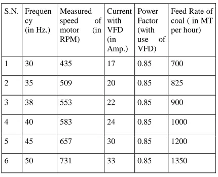
Website: www.ijetae.com (ISSN 2250-2459, ISO 9001:2008 Certified Journal, Volume 4, Issue 3, March 2014) Following measurements are recorded by running one
[image:4.612.61.276.191.365.2]no. paddle feeder with variation of frequency and tabulated below in Table-5.
Table-5
observations of PF motor with VFD
S.N. Frequen cy (in Hz.)
Measured speed of motor (in RPM) Current with VFD (in Amp.) Power Factor (with use of VFD)
Feed Rate of coal ( in MT per hour)
1 30 435 17 0.85 700
2 35 509 20 0.85 825
3 38 553 22 0.85 900
4 40 583 24 0.85 1000
5 45 657 30 0.85 1200
6 50 731 33 0.85 1350
When VFDs are used to run the paddle feeders, the paddle feeders are available with speed variation of paddle wheel and hence, the control in feed rate to conveyor is available. The following measurements are recorded for conveyor parameters:-
Table-6 With VFD in PF motors
S.N. Current drawn
Voltage applied
Power Factor
Frequency Loading of coal
1 234A 415V 0.92 50Hz 1900MT/Hrs.
IV. CALCULATIONS
As per the observations of the above Tables following calculations are done:-
The rated capacity of conveyor is 2000MT/Hrs.
(1) (i) With Eddy Current coupling in paddle feeder operation the conveyor power consumption and utilization is calculated as:-(as per table no.2)
Active Power consumed by conv = √3*V*I*Cosф
= 1.732*415*232*0.84 = 140.07kw
Reactive Power consumed by conv = √3*V*I*Sinф = 1.732*415*232*0.54
= 90.45kvar
% Conveyor utilization = 1700*100/2000 = 85%
(ii) With fluid coupling in paddle feeder operation the conveyor power consumption and utilization is calculated as:-(as per table no.4)
Power consumption in conveyor = √3*V*I*Cosф = 1.732*415*194*0.75
= 104.58kw
Reactive Power consumed by conv = √3*V*I*Sinф
= 1.732*415*154*0.66 = 92.21kvar
% Conveyor utilization = 1200*100/2000 = 60%
(iii) With VFD in paddle feeder operation the conveyor power consumption and utilization is calculated as:-(as per table no.7)
Power consumption in conveyor = √3*V*I*Cosф = 1.732*415*234*0.92
= 154.73kw
Reactive Power consumed by conv = √3*V*I*Sinф = 1.732*415*234*0.39
= 65.90kvar
% Conveyor utilization = 1900*100/2000 = 95%
The calculated results are tabulated below in table-7:-
Table-7
S.N. Type of coupling in PF
Power consum ption in convey or (in kw)
Reactive Power consump tion of conv (in kvar)
Utiliza tion of conve yor (in %)
Power factor
Coal on conveyor ( MT/hrs.)
1 Eddy current
140.07 90.45 85 0.84 1700
2 Fluid Coupling
104.58 92.21 60 0.75 1200
3 VFD 154.73 65.90 95 0.92 1900
International Journal of Emerging Technology and Advanced Engineering
Website: www.ijetae.com (ISSN 2250-2459, ISO 9001:2008 Certified Journal, Volume 4, Issue 3, March 2014)
Fig.7 Graph between type of coupling in PF and reactive power consumption in conveyor
Fig.8 Graph between type of coupling in PF and conveyor utilization
(2). (i) While operation of the Paddle Feeders is done with the eddy current coupling at 1200MT/hrs. feeding rate the current taken by the paddle feeders is 47A at 415V and 0.6p.f. (as per table-1).
Power consumption in paddle feeder = √3*V*I*Cosф
= 1.732*415*47*0.6 = 20.26 kw
(ii)While operation of the Paddle Feeders is done with the fluid coupling at 1200MT/hrs. Feeding rate the current taken by the paddle feeders is 48A at 415V and 0.6p.f. ( as per table-3).
Power consumption = √3*V*I*Cosф
= 1.732*415*48*0.6 = 20.70kw
(iii) While operation of the Paddle Feeders is done with the VFD at 1200MT/hrs. Feeding rate the current taken by the
paddle feeders is 30 A at 415V and 0.85 p.f. (as per table-5).
Power consumption = √3*V*I*Cosф
= 1.732*415*30*0.85 = 18.32 kw
The calculated results are tabulated in table-8 as:-
Table-8
power consumption in PF with different couplings
S.N. Type of coupling in PF
Power consumption in PF (in kw)
1 Eddy current 20.26
2 Fluid Coupling 20.70
3 VFD 18.32
Following graph is plotted between the above parameter for showing the comparison:-
Fig.9 Graph between type of coupling & power consumption in PF
International Journal of Emerging Technology and Advanced Engineering
Website: www.ijetae.com (ISSN 2250-2459, ISO 9001:2008 Certified Journal, Volume 4, Issue 3, March 2014) Table-9
S.N. Frequency (in Hz.)
Measured speed of motor (in RPM)
Current with VFD (in Amp.)
Speed at 4% slip (in
RPM)
1 30 435 17 432
2 35 509 20 504
3 38 553 22 547
4 40 583 24 576
5 45 657 30 648
6 50 731 33 720
From Table -5 following graph is plotted between frequency and current drawn by PF motor with VFD:-
Fig.10 Graph between frequency & current drawn by PF with VFD
V. CONCLUSION
As shown in the Table-9 & fig.-10, by the use of VFDs in paddle feeders the current consumption at reduced speed is reduced very much and hence, huge saving of energy, the slip of the paddle feeder motor also reduced as measured speed is more than the rated 4% slip speed of PF motor. Also as shown in table-8 & fig.-9, for the same feeding rate in all three type of couplings in the PF i.e.1200MT/hour, the power consumption in VFD is very less as compared to other type of couplings.
As shown in table-7 and fig. 7 by use of VFD in paddle feeders the reactive power consumption of conveyor motor reduced considerable as compared to eddy current coupling & fluid coupling in paddle feeder motor due to maximum loading of the coal in conveyor, the power factor of the conveyor motor has improved hence, life of all the associated components with motor will increase.
Also as shown in table-7 & fig.8 the utilization factor of conveyor is maximum with the use of VFDs in paddle feeders, as a result of that the coal evacuation from track hopper is fast and running hour of the system is less causing huge saving of the energy.
Acknowledgment
Kind co-operation of the management as well as employees of NTPC Ltd. Korba for this academic work is highly acknowledged.
REFERENCES
[1] Thida Win, Nang Sabai, and Hnin Nandar Maung , World Academy of Science, Engineering and Technology 42 2008,"Analysis of Variable Frequency Three Phase Induction Motor Drive".
[2] A. de Almeida, F. Ferreira, and D. Both, “Technical and economical considerations in the application of variable-speed drives with electric motor systems,” IEEE Trans. Ind. Appl., vol. 41, no. 1, pp. 18. [3] Neetha John, Mohandas R, Suja C Rajappan, International Journal of
Emerging Technology and Advanced Engineering Website: www.ijetae.com (ISSN 2250-2459, ISO 9001:2008 Certified Journal, Volume 3, Issue 3, March 2013) 784 , "Energy Saving Mechanism Using Variable Frequency Drives".
[4] Book on "Practical Variable Speed Drives and Power Electronics"
By Malcolm Barnes
[5] "Operation And Application Of Variable Frequency Drive (VFD)TECHNOLOGY",Carrier Corporation Syracuse, Tech note,New York October 2005.
[6] variable Frequency Drives And Energy Savings",By: Stephen Prachyl,White Paper,April 2010,Siemens Industry.
[7] "Energy Savings with Variable Frequency Drives",2007 , Tech note, Rockwell Automation.
[8] "Power generation Medium voltage drives for more efficient and reliable plant operation",Power Brochure ABB 2011.
[9] "Variable Frequency Drives",Energy Efficiency Reference Guide by Ceati International.
[10] "Adjustable Speed Drive", Reference Guide,Fourth Edition, August 1997,Revised by:Richard Okrasa, P.Eng.Ontario Hydro.
[11] Waide, Paul; Brunner, Conrad U. (2011). . International Energy Agency. Retrieved Jan. 27, 2012."Energy-Efficiency Policy Opportunities for Electric Motor-Driven Systems".
[12] Eisenbrown, Robert E. (May 18, 2008). "AC Drives, Historical and Future Perspective of Innovation and Growth". Keynote Presentation for the 25th Anniversary of The Wisconsin Electric Machines and Power Electronics Consortium (WEMPEC). University of Wisconsin, Madison, WI, USA: WEMPEC.
[13] Brochures, Vacon Plc Runsorintie 7, 65380 Vaasa, Finland. [14] Technical guide – Induction motors fed by PWM frequency
inverters- by WEG.