International Journal of Emerging Technology and Advanced Engineering
Website: www.ijetae.com (ISSN 2250-2459, ISO 9001:2008 Certified Journal, Volume 4, Issue 10, October 2014)
79
Command of the Active and Reactive Stator Powers of the
Doubly-Fed Induction Generator Used in Wind Energy
Abdelhadi EL MOUDDEN
1, Abdelali AARIB
2, Aïcha WAHABI
3, Fatima Ezzahra BOUNIFLI
4 1Empowered Professor, 2,4Doctoral Student, The National School of Electricity and Mechanics (ENSEM), University Hassan II
Aïn Chock, Casablanca, Morocco
3Assistant Professor, The superior school of technology (EST), University Hassan II Aïn Chock, Casablanca, Morocco
Computing laboratory, systems and renewable energies (LISER) analysis team and control of electrical energy systems (ACSEE), the National School of Electricity and Mechanics (ENSEM), University Hassan II Aïn Chock, Casablanca,
Morocco.
Abstract—The objective of this article is the behavioral
research of the asynchronous machine with double feeding used in the wind energy. The stator of the doubly-fed induction generator (DFIG) is directly connected with the grid. On the other hand, its rotor is connected to the latter via a waterfall (Rectifier, Filter and Inverter). The control of active and reactive powers of the wind turbine is realized by the regulation of the rotor sizes of the DFIG, while applying the indirect non linear command and the principle of control of the powers involvements between the grid and the wind energy is displayed. The approach used is to divert the law of command of the asynchronous machine with double feeding in permanent regime on all the range of speed, in generative mode. The first tool was evoked in a process of non-linear optimization of the electrical energy delivered to the grid. Integrated into a wind system, the asynchronous generator with double feeding allows working on a wide range of speeds of wind, and pulling the maximum of power possible, for every speed of wind. Its stator circuit is directly connected to the electricity grid. The non linear command of the converters of power to PWM (pulse width modulation) allows us to set the reactive and active powers with a big precision. Finally the results of the dynamic behavior of the studied system are presented, which allowed us to justify the reliability of the proposed model and the elaborate command. The results are made in Matlab-Simulink.
Keywords—DFIG, Generator, Inverter, Matlab-Simulink, PWM, Rectifier, Wind Energy.
I. INTRODUCTION
The wind system using a DFIG and a converter "back-to-back", which connects the rotor of the generator and the grid, present numerous assets [2]. One of the advantages of this structure is that the converters of power used, are sized to channel through a fraction of the total power of the system [3-4].
Which allows us the reduction of the losses in the components of electronics power, the performances and the production of power do not depend only on the DFIG, but also on the manner in which the two parts of the converters are controlled. The converter of power side machine is called "Rotor Side Converter" (RSC) and the converter of power grid side is called "Grid Side Converter" (GSC) [5]. The converter of power side machine allows us to control the active power and the reactive power produced by the machine [6]. As for the converter grid side, it controls the tension of the bus DC and the power factor grid side. In this article, we present a technique of control of both converters of power. We shall analyze their dynamic performances in the environment Matlab-Simulink [1]. We begin with the study of the system studied, a modeling of the equations of the turbine and the asynchronous machine with double feeding in the mark will be presented [7]. Then the results of the simulation, and their interpretation in the end of the article [8].
II. DFIGWIND TURBINE MODEL
International Journal of Emerging Technology and Advanced Engineering
Website: www.ijetae.com (ISSN 2250-2459, ISO 9001:2008 Certified Journal, Volume 4, Issue 10, October 2014)
80
Fig. 1 : System studied of the DFIG [17]The stator is directly connected to the AC mains, whilst the wound rotor is fed from the Power Electronics Converter via slip rings to allow DIFG to operate at a variety of speeds in response to changing wind speed. Indeed, the basic concept is to interpose a frequency converter between the variable frequency induction generator and fixed frequency grid. The DC capacitor linking stator -and rotor- side converters allows the storage of power from induction generator for further generation [10]. To achieve full control of grid current, the DC-link voltage must be boosted to a level higher than the amplitude of grid line-to-line voltage. The slip power can flow in both directions, in other words to the rotor from the supply and from supply to the rotor and hence the speed of the machine can be controlled from either rotor- or stator-side converter in both super and sub-synchronous speed ranges [11]. As a result, the machine can be controlled as a generator or a motor in both super and sub-synchronous operating modes realizing four operating modes. Below the synchronous speed in the motoring mode and above the synchronous speed in the generating mode, rotor-side converter operates as a rectifier and stator-side converter as an inverter, where slip power is returned to the stator [12]. Below the synchronous speed in the generating mode and above the synchronous speed in the motoring mode, rotor-side converter operates as an inverter and stator rotor-side converter as a rectifier, where slip power is supplied to the rotor. At the synchronous speed, slip power is taken from supply to excite the rotor windings and in this case machine behaves as a synchronous machine.
III. MODELING OF THE TURBINE
The model of the mechanical power developed by the turbine :
(1)
is called the power coefficient, which expresses the aerodynamic efficiency of the wind turbine. It depends on the ratio which expresses the relation between the speed
at the end of blades and the wind speed; the ratio can be
expressed by the following relation
: Rotation speed of the turbine (rad/s)
: Speed of wind (m/s)
: Radius of the swept area by the blades (m)
The maximum of the power coefficient was
determined by Albert Betz (1920) as follows :
The aerodynamic couple on the slow axis can be expressed by the equation:
(2)
The mechanical speed is connected to the speed of rotation of the turbine by the coefficient of the multiplier. The couple on the slow axis is connected with the couple on the fast axis (side generator) by the coefficient of the multiplier.
Fig. 2 : Power coefficient as a function of tip speed ratio and pitch
angle [3]
: Blades pitch angle (degree)
: Tip speed ratio (dimensionless)
: Air density (kg/m3)
: The surface crossed by the wind (m2)
International Journal of Emerging Technology and Advanced Engineering
Website: www.ijetae.com (ISSN 2250-2459, ISO 9001:2008 Certified Journal, Volume 4, Issue 10, October 2014)
81
IV. MODELING OF THE DFIG
The electric equations of the DFIG in the reference frame can be spelt[13] :
(3)
(4)
(5)
(6)
: The flux linkage (Wb) : The flux linkage (Wb) : The resistance (Ω) and : The stator and rotor electrical angular velocity (rad/s) The indices d and q indicates the direct and quadrature axis components of the reference frame r and s indicates rotor and stator quantities, respectively. All quantities in (3), (4), (5) and (6) are functions of time. By aligning the stator flux vector with the axis d, we can write [9] : (7)
(8)
The electromagnetic couple becomes[2] : (9)
The expression of the active and reactive stator powers becomes [15] :
{
(10), (11)
V. INDIRECT COMMAND OF THE DFIGUSED IN THE WIND
ENERGY
To improve the previous command, we introduce an algorithm of indirect command of active and reactive powers of the DFIG, according to the rotor currents, hence
the terms of coupling and
considered as being not unimportant disturbances, and will be compensated [13]. The command, so decoupled, is realized by means of regulators PI. There are two methods of decoupling in opened loop and in closed loop to control the stator powers. In our study we are interested in indirect control in opened loop.
: Sliding of the machine (dimensionless)
: Leakage flux total coefficient (dimensionless)
: Rotor inductance (H)
: Mutual inductance (H)
A. The indirect command in opened loop
The plan of the set commands block decoupling machine is illustrated on the figure 3. In this method, the decoupling is made at the level of the exits of regulators in rotor currents without any return to the system, by imposing the
reference tensions and which are convenient.
Therefore, the command by overlapped loop which controls the current is then applied to the DFIG for reasons of security of functioning [14]. Besides, the indirect command without locking up of power (in opened loop) allows us to control separately the currents and
in closed loop and the powers and , in opened loop
International Journal of Emerging Technology and Advanced Engineering
Website: www.ijetae.com (ISSN 2250-2459, ISO 9001:2008 Certified Journal, Volume 4, Issue 10, October 2014)
82
TABLEI
PARAMETERS OF THE MACHINE [19]
Parameters Values
Nominal power 1,5 MW
Nominal voltage 240 kV
Nominal frequency 50 HZ
Stator inductance 0.0060 H
Rotor inductance 0.0060 H
Fig. 3 : Open-loop command [18]
: Cyclic stator inductance (H) : Cyclic rotor inductance (H)
: Cyclic mutual inductance (H)
: Angular velocity of the stator (rad/s)
: Regulator proportional integral
: Stator active power (W)
: Stator reactive power (VAR)
: Stator reactive power reference (VAR)
: Stator active power reference (W)
𝑟𝑒𝑓 𝑟
𝑟 𝑟 𝑟𝑒𝑓
𝑟
𝑐𝑟
𝐼
𝑀
𝑐𝑟
𝑀 𝐼
𝐼
2
𝐃𝐅𝐈𝐆
𝑀𝑐
+ + + +
+
-+
-+ +
[image:4.612.57.556.145.603.2]International Journal of Emerging Technology and Advanced Engineering
Website: www.ijetae.com (ISSN 2250-2459, ISO 9001:2008 Certified Journal, Volume 4, Issue 10, October 2014)
83
[image:5.612.48.290.133.453.2]VI. RESULTS OF SIMULATION AND DISCUSSIONS
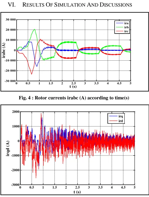
Fig. 4 : Rotor currents irabc (A) according to time(s)
Fig. 5 : Rotor currents irqd (A) according to time (s)
[image:5.612.321.566.134.283.2]The rotor currents depend on the variation of the speed of asynchronous machine with double feeding, and on the variation of the sliding of the machine according to the absorption or the supply of the rotor power, we can remark that irabc (A) vary between (-20 000 A) and (20 000 A), and irqd (A) vary between (-2000 A) and (2000 A) which is appropriate with the high power wind turbines.
Fig. 6 : Stator currents isabc (A) according to time (s)
Fig. 7 : Stator currents isqd (A) according to time (s)
[image:5.612.323.566.390.538.2]The stator currents vary in a sinusoidal way; they follow the evolution of the active stator power of the DFIG, the stator currents are independent of the profile of the wind’s speed, the currents isabc (A) vary between (-400 A) and (300 A), it undergoes a fluctuation, between time of 4.98 seconds and 4.99 seconds and the isqd (A) current vary in sinusoidal way between (-400 A) and (400 A).
Fig. 8 : Stator voltages Vsqd (V) according to time (s)
The forms of waves of the stator tensions are independent, of the speed of wind and they are equal to the tensions of the grid, the stator voltages Vsqd (V) vary between (-160 V) and (160 V), and as staircase between 4.99 seconds and 5 seconds.
0 0.5 1 1.5 2 2.5 3 3.5 4 4.5 5
-30 000 -20 000 -10 000 0 10 000 20 000 30 000
t (s)
ir
ab
c (A
)
ira irb irc
0 0.5 1 1.5 2 2.5 3 3.5 4 4.5 5
-3000 -2000 -1000 0 1000 2000
t (s)
ir
q
d
(A
)
irq ird
4.98 4.985 4.99 4.995 5 5.005
-500 -400 -300 -200 -100 0 100 200 300 400
t (s)
is
ab
c
(A
)
isa isb isc
4.98 4.985 4.99 4.995 5 5.005 -500
0 500
t (s)
is
q
d
(A
)
isq isd
4.98 4.985 4.99 4.995 5 5.005
-200 -150 -100 -50 0 50 100 150 200
t (s)
V
sq
d
(V
)
[image:5.612.49.292.559.698.2]International Journal of Emerging Technology and Advanced Engineering
Website: www.ijetae.com (ISSN 2250-2459, ISO 9001:2008 Certified Journal, Volume 4, Issue 10, October 2014)
[image:6.612.50.292.121.299.2]84
Fig. 9 : Generator speed (rad /s) according to time (s) [image:6.612.321.568.126.298.2]The mechanical speed of rotation of the machine, depends on the speed of wind and on the aerodynamic regulations, it vary between (-1000 rad/s) and (0 rad/s), in a simulation time of 5s which is suitable for high power wind turbine the results of the simulation shows that we work in the generator mode.
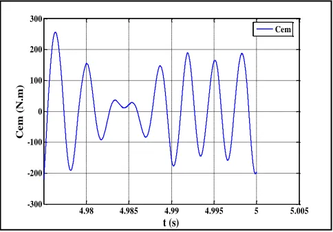
Fig. 10 : Electromagnetic couple Cem (N.m) according to time (s)
[image:6.612.324.566.372.545.2]The electromagnetic couple depends on the variation of the rotor currents. It is independent from the speed of wind, it vary in a sinusoidal way between (-250 N.m) and (250 N.m). It fluctuates between 4.98 seconds and 4.99 seconds, and it depends from the rotor current .
Fig. 11 : Curve rotor flux (Wb) in the mark qd according to time (s)
The rotor flux depends on the variation of the rotor power, it is independent from the wind speed of the machine, it vary between (-0,3 Wb) and (0,25 Wb), their shape is appropriate for the stator voltages.
Fig. 12 : Rotor voltages Vrqd (V) according to time (s)
The frequency of rotor tensions depends on the sliding of the machine. For a zero sliding (synchronous mode), the rotor tensions are constant, the rotor voltage Vrqd (V) vary between (-100 V) and (150 V), and it is independent from the profile of wind, it depends only from the rotor flux
(Wb) and rotor currents (A).
0 0.5 1 1.5 2 2.5 3 3.5 4 4.5 5 -1000
-800 -600 -400 -200 0
t (s)
G
e
n
e
r
ator
s
p
e
e
d
(r
ad
/s
)
Generator speed
4.98 4.985 4.99 4.995 5 5.005 -300
-200 -100 0 100 200 300
t (s)
C
e
m (N
.m)
Cem
4.98 4.985 4.99 4.995 5 5.005
-0.4 -0.3 -0.2 -0.1 0 0.1 0.2 0.3
t (s)
F
lu
x r
q
d
(Wb
)
Flux rq Flux rd
4.98 4.985 4.99 4.995 5 5.005
-150 -100 -50 0 50 100 150 200
t (s)
V
r
q
d
(V
)
[image:6.612.49.291.396.565.2]International Journal of Emerging Technology and Advanced Engineering
Website: www.ijetae.com (ISSN 2250-2459, ISO 9001:2008 Certified Journal, Volume 4, Issue 10, October 2014)
[image:7.612.49.291.125.281.2]85
Fig. 13 : Voltage of continuous bus Vdc (V) according to time (s) [image:7.612.49.291.341.480.2]The Voltage of continuous bus Vdc, which allows us to control the active power injected in the grid, it has a maximum of (1500 V), and a minimum of (90 V).
Fig. 14 : Stator active powers Ps (W) according to time (s)
The active stator powers depends on the variation of the stator currents, of the machine and of the sliding of the machine, it vary between (-60 MW) and (45 MW), which is adapted to high power wind turbine, the simulation time is 5 seconds.
Fig. 15 : Stator reactive powers Qs (VAR) according to time (s)
The reactive stator powers has a zero value, which allows us to decrease the losses on the grid, it vary between (-800 VAR) and (400 VAR), the simulation time is 5 seconds, and it depends from the rotor current .
VII. CONCLUSIONS
We have studied the behavior of the asynchronous machine with double feeding, when we apply the indirect open looped command of the DFIG, and the indirect command in power remains the robust and suitable command for a DFIG used in the wind energy, we have also presented the equations which govern the behavior of the DFIG and we have showed how we can obtain various results with Matlab-Simulink, the DFIG is able to provide a considerable contribution to grid voltage support during short circuit periods. The doubly fed induction generator system presented in this article offers many advantages to reduce cost and has the potential to be built economically at power levels 1,5 MW .Considering the results it can be said that doubly fed induction generator proved to be more reliable and stable system when connected to grid side with the proper converter control systems.
REFERENCES
[1] Matlab-Simulink
[2] L. Xu and C. Wei, « Torque and Reactive Power Control of a Doubly Fed Induction Machine by Position Sensorless Scheme». IEEE Trans, Industry Application, vol. 31, no. 3, pp. 636-642, May/June 1995.
[3] S. HEIER, Grid Integration of Wind Energy, Conversion Systems. New-York : John Wiley & Sons Ltd (1998).
[4] W. L. Kling and J. G. Slootweg, « Wind Turbines as Power Plants». in Proceeding of the IEEE/Cigré workshop on Wind Power and the impacts on Power Systems, 17-18 June 2002, Oslo, Norway. [5] T. Ackermann and Solder, L. « An Overview of Wind
Energy-Status 2002 ». Renewable and Sustainable Energy Reviews 6 (1-2), 67-127 (2002).
[6] T. Burton, D. Sharpe, N. Jenkins and E. Bossanyi, Wind Energy Handbook. John Wiley&Sons, Ltd, 2001.
[7] X. YAO, C. YI, D. YIN, J. GUO and L. YANG, « The grid-side PWM Converter of the Wind Power Generation System Based on Fuzzy Sliding Mode Control », Advanced Intelligent Mechatronics, IEEE 2008, Xian (Chine).
[8] X. YU, K. STRUNZ, « Combined long-term and shortterm access storage for sustainable energy system », 2004 IEEE Power Engineering Society General Meeting, vol.2, pp.1946-1951, 10 June 2004.
[9] D. Seyoum, C. Grantham, «Terminal Voltage Control of a Wind Turbine Driven Isolated Induction Generator using Stator Oriented Field Control». IEEE Transactions on Industry Applications, pp. 846-852, September 2003.
0 0.5 1 1.5 2 2.5 3 3.5 4 4.5 5
0 500 1000 1500
t (s)
V
d
c
(V
)
Vdc
0 0,5 1 1,5 2 2,5 3 3,5 4 4,5 5
-80 000 000 -60 000 000 -40 000 000 -20 000 000 0 20 000 000 40 000 000 60 000 000
t (s)
P
s (W)
Ps Ps reference
0 0.5 1 1.5 2 2.5 3 3.5 4 4.5 5
-800 -600 -400 -200 0 200 400
t (s)
Q
s (V
A
R
)
[image:7.612.48.293.564.704.2]International Journal of Emerging Technology and Advanced Engineering
Website: www.ijetae.com (ISSN 2250-2459, ISO 9001:2008 Certified Journal, Volume 4, Issue 10, October 2014)
86
[10] W. Hofmann, F. Okafor, (2001) : Doubly-Fed Full-ControlledInduction Wind Generator for Optimal Power Utilization. Proceeding of 4th IEEE International Conference on Power Engineering and Drive Systems, Vol. 1, pp. 355 – 361.
[11] S. Muller, M. Deicke and W.DeDoncker, ―Doubly fed induction generator systems for wind turbine,‖ IEEE Industry Applications Magazine, Vol.3, pp. 26-33.2002.
[12] R. Pena, J. C. Clare and G. M. Asher, ―Doubly fed induction generator using back-to-back PWM converts and its application to variable speed wind-energy generation,‖ IEE Proceedings Electrical Power Application, Vol. 143, pp. 231-241 (1996).
[13] Sandy Smith,Rebecca Todd and Mike Barnes ―Improved Energy Conversion for Doubly- Fed Wind Generators‖, Proceedings of IAS 2005, pp. 7803-9208, June 2005.
[14] Lucian Mihet-Popa, FredeBlaabjerg, ―Wind Turbine Generator Modeling and Simulation Where Rotational Speed is the Controlled Variable‖, IEEE Transactions on Industry Applications, Vol. 40.No.1,January/February 2004.
[15] V.Akhmatoy and H.Krudsen, ―Modelling of windmill induction generator in dynamic simulation programs,‖ Proc. IEEE Int. Conference on Power Technology, Budapest,Hungary, paper No. 108. Aug 1999.
[16] Debiprasad P., Benedict E. L. Venkataramanan G. and Lipo T. A. ―A Novel Control Strategy for the Rotor Side Control of a Doubly-Fed Induction Machine‖, Proceedings of Thirty-Sixth IAS Annual Meeting Conference IEEE, Vol.3, 30 Sep.-4 Oct. 2001, pp. 1695-1702.
[17] ABB Technical application papers no.13, "Wind power plants," ABB document 1SDC007112G0201 - 10/2011 - 4.000.
[18] Mekkaoui Naima, "Contribution à la Modélisation et à la Commande d’une Mini-Centrale Eolienne à Base de Machines à Induction Simple et Double Alimentée", Mémoire de Magister université batna(Algérie), pp. 98, promotion 2004.
[19] S. E. AIMANI, "Modélisation de différentes technologies d'éoliennes intégrées dans un réseau de moyenne tension", Thèse de Doctorat, École Centrale de Lille (France), 2004.
AUTHORS'PROFILE
Dr. EL MOUDDEN Abdelhadi : Doctor of Science from The National Polytechnic Institute of Toulouse (INPT) in 1993 - FRANCE.
He is now a professor in the National School of Electricity and Mechanics (ENSEM), University Hassan II Aïn Chock, Casablanca, Morocco.
Since 2006, he has been a member of Laboratory Computing, Systems and Renewable Energies (LISER), Research Group: Analysis and Control Systems of Electrical energy (ACSEE).
His research interests include Dynamic Simulations of Electric Machinery, Simulation and Optimization of Renewable Energy Systems. He has presented and published many articles in scientific journals and conferences (IEEE).
Doctoral student : AARIB Abdelali I am in the process of preparing a doctoral thesis in the National School of Electricity and Mechanics (ENSEM), University Hassan II Aïn Chock, Casablanca, Morocco.
Research Group: Analysis and Control Systems of Electrical energy (ACSEE) - Laboratory of Computing, Systems and Renewable Energy (LISER).
International Journal of Emerging Technology and Advanced Engineering
Website: www.ijetae.com (ISSN 2250-2459, ISO 9001:2008 Certified Journal, Volume 4, Issue 10, October 2014)
87
I am Mrs. Wahabi Aicha, an assistant professor at the superior school of technology (EST) in Casablanca, Morocco since 1991. From 2012 to the present, I’m a member of Laboratory of Computing, Systems and Renewable Energy (LISER), Research Group : Team Analysis and Control Systems of Electrical Energy (ACSEE).I wish to inform you that I'm preparing my habilitation in energy renewable more precisely wind energy turbine, in the National School of Electricity and Mechanics (ENSEM). I got the diploma of superior depth studies in 2000 in the National School of Electricity and Mechanic (ENSEM) Casablanca, Morocco, I am also an electromechanical engineer of the National School of Mineral Industry (ENIM) in Rabat, Morocco (in 1990).
I have already presented three papers in Morocco on wind energy during the years 2013 and 2014 and I've participated in a publication in an international journal.
BOUNIFLI Fatima-Ezzahra : I am a doctoral student preparing a doctoral thesis in the National School of Electricity and Mechanics (ENSEM), University Hassan II Aïn Chock, Casablanca, Research Group: Analysis and Control Systems of Electrical energy (ACSEE) - Laboratory of Computing, Systems and Renewable Energy (LISER).
On June 2013, I got an engineering diploma specialized in electrical energy in ENSEM. My doctoral thesis is about direct and fuzzy-logic control systems of the double-feed induction generator wind turbine. I've submitted my first technical paper to (AMT) international scientific conference (22/04/2014). I also presented two oral communications in Morocco on the wind energy during the year 2014 and I participated in a publication in an international journal.
![TABLE PARAMETERS OF THE I MACHINE [19]](https://thumb-us.123doks.com/thumbv2/123dok_us/8707640.881090/4.612.57.556.145.603/table-parameters-i-machine.webp)