Issue 1
PAGEPAC PLUS CONTROLLER CONFIGURATION
PROGRAMMING GUIDE (V-5335800)
by
PagePac
®INTRODUCTION
The PagePac® Plus User Interface software package runs on a generic DOS-based IBM PC or compat-ible. It requires no more than 640K RAM and a single 3.5 inch floppy-disk drive. The program operates in character mode, and supports both monochrome (MDA or Hercules) and color (CGA or above) dis-plays and adapters. It uses color if it is available and provides a high-contrast color scheme for use on machines with Liquid Crystal Displays (LCD). The Controller unit has the ability to retain the configura-tion opconfigura-tions indefinitely.
The PC connects to an RS-232 port on the rear of the Controller by means of a crossover cable (also called a null-modem cable).
BEFORE YOU BEGIN PROGRAMMING
1. Fill out Zone Map and Configuration Tables.
Paging zone decisions should be made and diagrammed prior to programming. Refer to the Zone Map and Zone Configuration Tables in the PagePac Plus Paging Controller Programming and Operation Guide.
2. Set Zone Option Switches.
3. If you are using the Zone Mapping feature (page 11), you must determine the controller firmware Issue # before programming. Page 12 describes this procedure.
The slide switch for each zone must be manually set to one of the following options, depending on the programmed mode selected for each zone:
• Contact Closure Output (to switch on/off a device, such as a door security lock, remote amplifier, etc.) • Contact Closure Input (such as doorbell or security alarm interface)
• 70V Output for audio
4. Set Dip Switches.
If Zone Expansion Units are installed, the DIP switch on each unit must be set prior to powering up the system, and prior to programming. Refer to the PagePac® Plus Controller Installation and Use Guide, or to the Zone Expansion Unit Installation and Use Guide, for instructions.
LOADING/STARTING THE PROGRAMMING SOFTWARE
1. Turn on PC.
Let it boot up. At the DOS prompt C:>> on the screen:
3. Type <<drive letter>>: [ENTER].<W9IV>
Type A: (or B:) and press [ENTER] to direct the DOS system to the correct disk drive. 4. Type PPPLUS [ENTER].
The introductory screen will come up, displaying the PagePac® Plus startup screen.
The following command line switches listed can be used after the execute name, i.e.,
PPPLUS /BW [ENTER].
5. Press any key to continue.
The screen will be blank except for the Menu Bar across the top of the screen (visible in figure 1).
WHICH FILE TO OPEN?
If you want to make changes to the configuration that is currently in use by the PagePac® Plus system, perform step 1. If you want to use the original default configuration (or another version that you have previously saved) to make changes and then send to the Controller, go to step 2.
1. Change the current configuration. a. Select Transfer from the Menu Bar. b. Select Receive from the Transfer menu.
This will place a copy of the current configuration into the PPPLUS program. You may make changes to it and then use the Transfer/Send option to send your modified configuration back to the Controller.
2. Use the default configuration (or another saved version). a. Select File from the Menu Bar.
b. Select the Load option from the File menu.
You will be prompted to enter the name of the file you wish to load. If no name is entered, the default file will be loaded.
You may make changes to it and then use the Transfer/Send option to send your modified configuration back to the Controller.
Switch
Description
/BW
forces black & white display mode
/COMn
selects serial port; also available via options menu item (COM1-COM4)
/ISSUEn
sets zone map format; also available via config I Map (ISSUE1 or ISSUE2)
RECOMMENDED PROCEDURE
Follow this summary of steps to implement the configuration changes you wish to make. Depending on your needs, you may wish to go directly to the menu(s) and table(s) that access the specific options you wish to change. Detailed instructions for each step are provided elsewhere in this guide.
1. Load the configuration to be modified. See “Which File to Open” (page 2).
2. Make changes to System Parameters. See “System Parameters” (page 6).
3. Make changes to individual Zone or Group Parameters. See “Zone/Group Parameters” (page 8). Repeat this step for each zone or group.
4. Define or change the make-up of a Zone Group. See “Zone Groups” (page 10). Repeat this step for each group.
5. Make changes to Zone Mapping. See “Zone Mapping” (page 11).
6. Send your new configuration to the Controller. See “Transfer Menu” (page 13).
7. Change Monitor or Log File setup. See “Monitor Menu” (page 15).
ABOUT THE SCREEN
Use your keyboard or mouse to select from the Menu Bar, and from all other menus in this program.
Mouse—put the cursor on the option you wish to select, and click the left mouse button once, to select.
Keyboard—use arrow keys, or type first letter of the option name, to move the cursor to the option. Then press [ENTER] to select the option.
ESC key
Press [ESC] (escape key) to get out of any menu and return to the menu bar. The File Menu provides the Exit option. Select Exit to get out of the programming software and return to the DOS prompt.
F1 HELP
Press [F1] for context-specific HELP at any point in any of the tables.
Menu Bar
The menu bar is always visible across the top of the screen (see figure 1). Use the keyboard or mouse to activate a pull-down menu from the Menu Bar.
[ALT] + Highlighted letter
FILE MENU
The File menu allows you to create a new configuration, load an existing one, or save the current config-uration (including any changes made) on disk. Use the arrow keys to highlight your selection, then press
[ENTER]. Press [ESC] to abort any of these options and return to the Menu Bar.
NOTE: File Name Prefix—A configuration file name consists of a prefix up to 8 characters in length, fol-lowed by a suffix (CFG). You choose what you wish to call a new file (the prefix), and the PPPLUS pro-gram will automatically use the CFG suffix.
1. Select New, Open, Save, or Exit.
New resets the current configuration to the factory default values, discarding any changes previously made.
Open loads configuration data from a disk file that you have previously named and saved. You will be prompted to Open a New File by entering a new file name prefix.
Save a configuration file that you are asked to name. You can save a new file that you create (by giv-ing it a new name prefix), or save changes to an existgiv-ing file (by savgiv-ing it without changgiv-ing the file name).
Exit takes you out of the programming software and back to the DOS prompt.
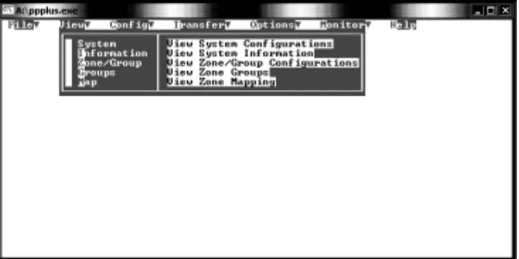
VIEW MENU
The view menu enables you to view (but not alter) the configuration that is currently loaded into the PagePac® Plus Controller. You can view the system parameters, individual zone configurations, zone groupings, or the zone mapping (the telephone extension numbers assigned to zones and groups).
Each of these options brings up a table similar to the tables under the Config Menu.
Select an Option, press [ENTER]. Options are:
• System (View System Configurations) • Information (View System Information)
• Zone/Group (View Zone/Group Configurations) • Groups (View Zone Groups)
• Map (View Zone Mapping)
Figure 2. View Menu
CONFIG MENU
The Config menu selects the portion of the loaded configuration to be edited. Each of these options brings up a table where more specific options are to be selected (see figure 3, below). Use the arrow key to highlight your selection and press [ENTER] to select, or click the mouse button on your selection. Select an Option, press [ENTER].
Options are:
• System (System Parameters)
• Zone/Group (Zone/Group Parameters) • Groups (Zone Groups)
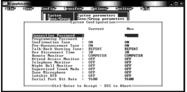
SYSTEM PARAMETERS
System Parameters apply system-wide, and are not zone-specific. Choosing this configuration option brings up a table in which further options may be set. Press [F1] for context-specific HELP. For further information about system parameters, refer to the PagePac® Plus Controller Programming and Use Guide.
The following functions allow you to maneuver within the tables.
• The arrow keys , <<up, down>> move the cursor within the table.
• Use the Space Bar to toggle between options.
• Press [ENTER] to select a setting.
• Press [CTRL] plus [ENTER] to accept changes and exit table.
Figure 3. System Parameters Table 1. Connection Password—Type password (or leave blank).
Enter a connect password to restrict access to the PagePac® Plus paging system. A password can have up to 6 digits (characters are not allowed). Leave blank if no password is desired. Press [ENTER]
to set the password. The default is no password (blank).
2. Programming Password—Type password (or leave blank).
Leave blank if no password is desired. Type up to 6 digits to set a programming password.
(Characters are not allowed.) Press [ENTER] to set the password. The default is no password (blank). 3. Confirmation Tone—ON or OFF.
Use space bar to toggle between ON and OFF. Then press [ENTER]. The default setting is ON. 4. Pre-Announcement Tone—ON or OFF.
Use space bar to toggle between ON and OFF. Then press [ENTER]. The default setting is ON. 5. Talkback Warning Tone.
Valid settings are OFF, INITIAL, and REPEAT. Use space bar to toggle through options, then press
6. VOX Disconnect Time.
Valid settings are 00 (none), 10, 20, 30, 40, 50, and 60 seconds. Use space bar to toggle through options, then press [ENTER] to select one. The default is 30 seconds.
7. Remote Monitor.
This parameter selects either the PC or a visual text display device as the remote monitor connected to the PagePac® Plus Controller. Valid choices are COMPUTER and DISPLAY. Use space bar to toggle through options, then press [ENTER] to select. The default is COMPUTER.
8. Attend Access Monitor.
With this parameter you choose whether to monitor Attendant Access paging activity. Use the space bar to toggle between ON and OFF, then press [ENTER] to select. The default is OFF.
9. Telephone Monitor.
Choose whether to monitor Telephone Access paging activity. Use the space bar to toggle between ON and OFF, then press [ENTER] to select. The default is OFF.
10. Night Bell Monitor.
Choose whether to monitor Nightbell activity. Use the space bar to toggle between ON and OFF, then press [ENTER] to select. The default is OFF.
11. Supervised Trunk Mode.
This parameter enables the Controller to disconnect the station to trunk connection in certain PABXs that have the ability to recognize a reverse disconnect sent by the Controller. Use the space bar to toggle between ON and OFF, then press [ENTER] to select. The default is OFF.
12. Zone Microphone.
This parameter allows you to specify that a zone microphone (or other audio input device) is attached to the Attendant Access interface. When the Zone Microphone option is enabled (ON), the controller will wait for a zone to be selected from the microphone keypad (DTMF tone) before it makes a page. When disabled (OFF), the controller reverts to all call without DTMF selection. Use the space bar to toggle between ON and OFF, then press [ENTER] to select. The default is OFF.
13. Inhibit Dial Tone Detect.
This parameter defeats the dial tone detect function in the event that the user desires to send a tone via the telephone interface to the page output. This feature is only applicable in the station access mode. Use the space bar to toggle between ON and OFF, then press [ENTER] to select. The default is OFF. 14. Serial Port Bit Rate.
ZONE/GROUP PARAMETERS
Zone/group options are specific to a zone or group, and do not apply to the system as a whole. When this option is selected, you are prompted to enter the 2-digit number of the zone or group for which you are setting parameters. Press [F1] for context-specific HELP.
For further information about zone/group configuration options, refer to the PagePac® Plus Controller Programming and User Guide.
1. Type Zone/Group Number.
Type the 2-digit physical zone number, from 01 to 56 (for individual zones) or from 80 through 88 (for groups), and press [ENTER]. Each zone or group must be programmed, so repeat these steps for each zone or group.
If you type a zone number (01 through 56), an options table will appear for that individual zone. Proceed with step 2, below.
If you type group number 80 (the default All Call group) or another group number (81 through 88), an options table will appear for that zone group. Proceed to step 15.
The following functions allow you to maneuver within the tables.
• The arrow keys , <<up, down>> move the cursor within the table. • Use the Space Bar to toggle between options.
• Press [ENTER] to select a setting.
• Press [CTRL] plus [ENTER] to accept changes and exit table. 2. Select OUTPUT or INPUT.
Is this zone to be an OUTPUT or an INPUT zone? If INPUT, two levels of priority are available:
INPUT(1) and INPUT(2). Use space bar to toggle, and press [ENTER] to select. The default Zone Type is OUTPUT.
3. Select OUTPUT TYPE.
For an OUTPUT zone only, select the type of output. The default output type is AUDIO (N/O). Press space bar to scroll through other options, Momentary, Normally Closed, System Handshake, Toggle, Phantom, and AAReady.
4. Page Enable YES/NO.
For an OUTPUT zone only, select YES to enable paging audio to this paging zone, and press [ENTER]. The default is YES.
5. Music Enable YES/NO.
For an OUTPUT zone only, select YES to enable background music to this audio zone, and press
[ENTER]. The default is NO. 6. Talkback Enable YES/NO.
Figure 4. Individual Zone Parameters Table
7. Night Bell Enable YES/NO.
For an OUTPUT zone only, select YES to enable the nightbell feature to be active in this zone. Then press [ENTER]. The default is NO.
8. Pass DTMF YES/NO.
For an OUTPUT zone only, select YES to pass touchtone telephone (DTMF) tones through this output zone (to another controller). Then press [ENTER]. The default is NO.
9. Select Input Closure Tone.
For an input contact closure zone, select the audio tone to be sounded when an input is active. Use space bar to scroll through the options: NONE, CHIME, FAST SIREN, WARBLE SIREN, NIGHT BELL, FAST RING, STEADY TONE, and DOORBELL. Then press [ENTER]. The default is NONE.
10. Tone Routing: Enter Zone Number.
Designate an output zone to receive the tone selected in the previous step. Type the 2-digit zone number, and press [ENTER].
11. Select Audio Source.
Select the audio source for paging in this output audio zone. Options are NONE, ATTENDANT ACCESS, and TELEPHONE. The default is NONE. Then press [ENTER].
12. Audio Routing: [ENTER] Zone Number.
Type the 2-digit zone number of the zone to which the audio is to be routed, and press [ENTER]. 13. Remote Monitoring YES/NO.
Choose YES to select this zone for remote monitoring by computer or display device. and press
[ENTER]. (The choice of computer or display device is made under System Parameters.) The default is NO.
14. Press [CTRL] plus [ENTER] to accept changes and exit table.
The steps that follow are for selecting Zone Group Parameters.
NOTE: When a conflict exists between an individual zone parameter (for example, Page Enable NO) and a parameter for a group that includes the zone (for example, group Page Enable YES), the group parameter will override the individual parameter whenever the group is accessed.
15. Page Enable YES/NO.
For a group of OUTPUT zones, select YES to enable paging audio to all zones in this group, and press
[ENTER]. The default is YES. 16. Talkback Enable YES/NO.
For a group of OUTPUT zones, select YES to enable talkback for all zones in the group, and press
[ENTER]. The default is NO. 17. Pass DTMF YES/NO.
For a group of OUTPUT zones, select YES to pass DTMF tones through these output zones (to another controller). Then press [ENTER]. The default is NO.
18. Remote Monitoring YES/NO.
Choose YES to select this group for remote monitoring by computer or display device and press
[ENTER]. (The choice of computer or display device is made under System Parameters.) The default is NO.
ZONE GROUPS
This option displays a table in which the user defines a group of zones. First, you are prompted to enter a Group Number for the group, then a table will appear in which you select individual zones to be included in this group. Repeat this procedure for each Zone Group.
For further information about zone grouping, refer to the PagePac® Plus Controller Programming and Use Guide.
1. Type Group Number.
Type a 2-digit number from 81 through 88, to identify this group. Press [ENTER]. A table will display, titled Group Configuration.
2. Select Zones.
Keyboard: use the arrow keys to move up and down in the current column of the table. Tab to advance from the bottom entry in one column to the top entry in the next. Use the space bar to select individual zones to make up this group. [Shift] + [Tab] move the selection backwards.
Mouse: highlight an individual zone and press the space bar to select. Repeat for other zones to be included in this group.
A check mark will appear next to the zone to indicate it has been selected.
3. Press [CTRL] + [ENTER] to accept changes and exit table.
Figure 5. Group Configuration Table
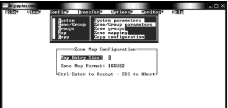
ZONE MAPPING
Selecting Map from the Config Menu first shows a prompt that asks you to indicate the map entry size, which is the number of digits (2, 3, or 4) you wish to use for telephone dialing of paging zones.
You are also prompted to select the zone map format. This only applies if 3 or 4 digits were selected on map entry size.
1. Enter Map Size (number of digits) and press [Enter]
Use the space bar to scroll through the available lengths: 2, 3, or 4 digits.
If you select 2-digits, you are automatically returned to the Menu Bar, since 2-digit numbers are the default zone identifiers.
2. Select ISSUE1 or ISSUE2 and press [Control]+[Enter]
Use the space bar to select the issue #. This identifies the firmware version of your unit. Review the pro-cedure on the next page to determine issue #.
If you selected 3-digit or 4-digit mapping, the program opens up a table called Zone/Group Re-Mapping.
3. Type Zone Alias Numbers.
Designate telephone dialing zone numbers for the individual zones 01 through 56 and zone groups 80 through 88.
From the Keyboard: use the arrow keys to move up and down the current column of the table. Press Tab key to advance from the bottom of one column to the top of the next.
[Shift] + Tab to move backwards.
Highlight field, then type in the Alias number (telephone dialing zone number of each zone). Press [ENTER].
Using the Mouse: highlight the zone, then type the zone number and press [ENTER]. All Alias numbers must have the same length, either 2, 3, or 4 digits.
NOTE: Pressing [ENTER] without typing in an Alias number results in a zero (0) Alias number. [Shift] + [Tab] moves the cursor backwards
4. Press [CTRL] + [ENTER] to accept changes and exit table.
To find out which Zone Map Format (Issue#) is in use:
1. Select Receive from the Transfer menu to transfer the current (default) configuration from the PagePac® Plus Controller to the computer.
NOTE: This procedure only needs to be done if Zone Mapping is used, and must be done before pro-gramming. Make sure null-modem cable is connected from the PC to the Controller.
2. When transfer is complete, go to the View menu and select Information.
3. If the number of installed zones and software checksum fields are blank, the Zone Map should be in ISSUE1 format.
If these fields contain values, then the Zone Map should be in ISSUE2 format.
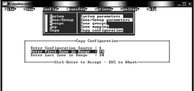
COPY CONFIGURATION
The Copy Configuration option allows you to copy the configuration of one configured zone, to another zone (or series of zones), without having to configure them individually.
1. Select COPY.
A table will appear in which you will indicate the zone you wish to copy from (the Source), and the zone(s) you wish to copy to (the Destination).
2. Enter source zone number (01 through 56).
3. Enter the beginning and end of the range of destination zone numbers.
4. Press [CTRL] + [ENTER] to accept (to activate the copy function).
Figure 7. Copy Configuration Option
TRANSFER MENU
The Transfer Menu opens an option box in which you may choose to Send your current configuration to the Controller, or Receive the Controller's current operating configuration to the User Interface program. You may also choose to connect directly to your PC's serial port, to control a modem.
CONNECT
Select Connect to communicate transparently with the serial port, facilitating operation with a modem to configure the Controller remotely.
SEND
Select Send to copy the currently loaded configuration to the Controller (The transfer takes about 12 seconds). This will then become the effective configuration of the paging system. It will remain in the Controller's memory until replaced by another Send action, or until modified by DTMF telephone keypad programming changes. Select Send and press [ENTER].
RECEIVE
The Receive option copies the Controller's current configuration to the computer. This option allows the user to capture (copy and view) any changes that may have been made to the paging system configura-tion by means of the DTMF telephone keypad. Once the configuraconfigura-tion has been received, you may view it, make changes to it (using the Config menu), save it to disk, and send your modified configuration back to the Controller.
Select Receive.
Figure 8. Transfer Menu
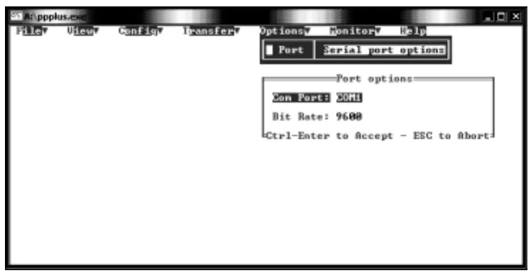
OPTIONS MENU
The Options Menu prompts the user to define the serial COM port of the computer or visual display that is used to interface with the PagePac® Plus Controller.
1. Select COM Port Number.
Figure 9. Options Menu, Port Options
Press space bar to toggle between the options (COM1, COM2, COM3, and COM4). Press [ENTER] to assign. The default is COM1.
2. Select Bit Rate.
Press space bar to toggle between the options (300, 1200, 2400, 4800, 9600, 14.4k, and 19.2k bps). Press [CNTL] + [ENTER] to accept changes and exit.
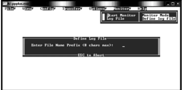
MONITOR MENU
The Monitor Menu permits the user to activate the automatic monitor function of the PagePac® Plus Controller (connected to the PC). It also permits the designation of a computer file for recording all mon-itor activity (the Log File option).
For further information about PC monitoring and logging of paging activity, refer to the PagePac® Plus Controller Programming and Use Guide.
1. Select Start Monitor.
2. Highlight the START MONITOR option and press [ENTER].
The screen will go blank except for the header “Paging Activity Monitor.” Leave this screen active, and the PC turned on, to enable the monitor function of the PagePac Plus Controller.
The screen will display the activity of the paging system in real time. Each message consists of a refer-ence number, a description, and a time stamp.
3. Press [ESC] to exit back to the Menu Bar. Press [F1] for context-specific HELP.
If you have defined a Log File, press [F2] (toggle) to activate (open) or deactivate (close) the Log File. 4. Select Log File
You will be prompted to name a Log File, which is a diskette file where the paging messages will be recorded. Enter a file name (up to 8 characters).
5. Press [ESC] to Abort. Press [F1] for context-specific HELP. A default Log File will be activated, and return to the Menu Bar.
To Activate the Log File
Select Start Monitor from the Monitor menu and press [F2].
To Log File to a Printer/Port
Type a file name of PRN or LPTn, and press [Enter].
For example, LPT1, LPT2, is the number of the parallel port to which your printer is connected.
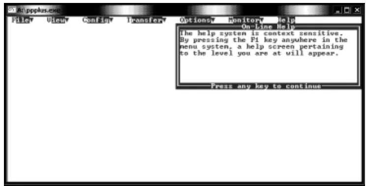
HELP MENU
The Help menu gives a brief description of the context-sensitive on-line help function, which is activated by pressing the [F1] key at any time during the PPPLUS program.
Figure 11. Help Menu
TECHNICAL ASSISTANCE
When calling, have a VOM and a telephone test set available and call from the job site. Call (540) 427-3900 and ask for PagePac Technical Support, or call (540) 427-6000 for Valcom 24-hour Automated Support or visit our websites at http://www.pagepac.com and www.valcom.com.
Should repairs be necessary, attach a tag to the unit clearly stating company name, address, phone number, contact person, and the nature of the problem. Send the unit to:
Valcom, Inc. PagePac® Repair Dept.