Available online: https://edupediapublications.org/journals/index.php/IJR/ P a g e | 1771
A Single-Phase To Three-Phase Power Conversion
System with Parallel Rectifier and Series Inverter
CH.RAVALI1 S. SAI KIRAN KUMAR2 D. RAMESH3
1PG Scholar, Dept of EEE(Power & Industrial Drives),Nova College Of Engineering & Technology,
Hyderabad, TS, India.
2 Associate Professor, Dept of EEE, Nova College Of Engineering & Technology, Hyderabad, TS, India
3 Associate Professor, Head of Dept (EEE), Nova College Of Engineering & Technology, Hyderabad, TS,
India
ABSTRACT:
This project presents a single-phase to three-single-phase power conversion system with parallel rectifier and series inverter to cope with single-phase to three-phase asymmetry. Such converter guarantees both reduction in the input current processed by rectifier circuit (due to the parallel connection) and reduction of the output voltage processed by each inverter (due to the series connection). It is worth mentioning that, in spite of proposing a topology with features not yet observed in the technical literature, this paper presents a comprehensive model of the proposed converter, modulation strategy, and a general comparison with theconventional configuration.
In extension we
proposed FUZZY controller and Simulated
results are also presented
.Key words: Rectifier, inverter, power
conversion, pulse width modulation
I.INTRODUCTION
In the power distribution systems, the
single-phase grid has been considered as an
alternative for rural or remote areas, due to
Available online: https://edupediapublications.org/journals/index.php/IJR/ P a g e | 1772
inherent asymmetry, i.e., constant power at the output-converter side (three-phase load) and pulsating power at the input-converter side (single-phase grid). The direct consequence of this asymmetry is the low frequency voltage oscillation observed in the dc-link capacitors, as well as the power switches of the rectifier and inverter operate with different voltage and current ratings. Normally, the three-phase
motor-rated voltage is higher than that furnished by the single-phase grid (considering the Brazilian voltages available, it is possible to identify: vim = 110 V, out = 220 V, or vim = 220 V, out = 220 V - depending of the region), which means that the rectifier circuit must boost the grid voltage to guarantee the motor-rated voltage.
Fig. 1. Single-phase to three -phase power conversion. Type of power processed by rectifier and inverter circuits.
Furthermore, the current relation between input- and output-converter sides also implies in converter asymmetry, i.e., (iin > iout ). Another important characteristic observed in the single-phase to three-single-phase power converters that also has been considered in this paper is the irregular distribution of power losses among the switches of the converter. It means that, for a 600 V 50A class of insulated gate bipolar transistor (IGBT),
Available online: https://edupediapublications.org/journals/index.php/IJR/ P a g e | 1773
important parameter regarding the possibilities of failures in the power converters. Many configurations have been considered to deal with this asymmetry, as in in which a parallel rectifier circuit is considered to reduce the current processed by rectifier switches, as well as to improve the harmonic distortion, reliability, and efficiency at the input-converter side. With the
same philosophy, Jacobin et al.proposes two
single-phase to three-phase ac–dc–ac converters paralleled [see Fig.], meaning improvements at input–output converter sides. To handle with the low-frequency voltage fluctuation observed in the dc-link voltage, Inhuman and Itch in and present a configuration with a specific control method for a single-phase to three-phase power converter with power decoupling function.
Fig.2. Proposed single -phase to three -phase conversion system.
Inverter (due to the series connection). It is worth mentioning that, in spite of proposing a topology with features not yet observed in the technical literature, this paper presents a comprehensive model of the proposed converter, modulation strategy, and a general comparison
with the conventional configuration.
Experimental results are used for the validation purpose.
III. MODELLING OF PROPOSED
SYSTEM:
This section will present the model of the proposed configuration. Such a configuration is constituted by a single phase grid (eg ), one open-end three-phase motor, inductor filters (L1a, L1b, L3b , and L3a ), converters 1, 2, 3,
and 4, and two dc link capacitor banks (C12 and
C34). If the legs are substituted by pulsed
Available online: https://edupediapublications.org/journals/index.php/IJR/ P a g e | 1774
A. Grid-Side Converter Model
From the system the following equations can be derived to converters 1 and 3 at the grid side :
where i1a and i1b are the input currents of the converter 1, i3a and i3b are the input currents of the converter 3, the symbols r and l represent the resistance and inductance of inductors L1a, L1b, L3a , and L3b . The voltages v1a01 2 and v1b01 2 are the pole voltages of the converter 1, while
v3a03 4 and v3b03 4 are the pole voltages of the converter 3 and ig is the grid current.
B. Machine-Side Converter Model
From the system the following equations can be derived to converters 2 and 4 at the machine side:
where v2a01 2 , v2b01 2 , and v2c01 2 are the pole voltages of converter 2, v4a03 4 , v4b03 4 , and v4c03 4 are the pole voltages of converter 4, and vab = va − vb, vbc = vb − vc , and vca = vc
– va are line-to-line voltages of the machine. For
Available online: https://edupediapublications.org/journals/index.php/IJR/ P a g e | 1775
C. Three-Phase Motor Model
A typical three-phase machine has been used in this study Selecting a fixed coordinate reference frame, the mathematical model that describes the
dynamic behavior of the three-phase induction motor is given by
where vsdq = vsd + jvsq , isdq = isd+jisq , and
φsdq = φsd + jφsq are the voltage, current, and
flux dq vectors of the stator, respectively; vso
and iso are the homopolar voltage and current of
the stator, respectively (the equivalent rotor variables are obtained by replacing the subscript
s by r); Te is the electromagnetic torque; ωr is the angular frequency of the rotor; rs and rr are
the stator and rotor resistances; ls, lls, lr , and llr
are the self and leakage inductance of the stator
and rotor, respectively; lsr is the mutual
inductance and P is the number of pole pairs of
the machine. The dqo stator variables of the
previous model can be determined from the abc
variables by using the transformation given by
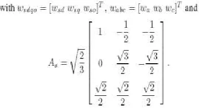
Vectors wsdqo and wabc can be voltage or current or flux vectors and A−1 s = ATs
IV. CONTROL STRATAGY
The proposed converter has the same objectives as in the conventional converter, as observed in Fig. 1(b), i.e., 1) dc-link voltage control, 2) power factor correction, and 3) three-phase voltage generation at the output-converter side. Additionally, the converter control of the
proposed system needs to control the circulating current. Fig. 3 presents the control block diagram for the proposed system. The capacitor
dc-link voltages vC1 2 and vC3 4 are adjusted to
their reference values v*C 1 2 and v*C 3 4 using
controllers RC1 2 and RC3 4 (conventional PI-type controllers), respectively. Those controllers
Available online: https://edupediapublications.org/journals/index.php/IJR/ P a g e | 1776
and i*3a . To control power factor and harmonic
content at the input-converter side, the instantaneous reference currents i*1a and i*3a
are synchronized with the grid voltage, as given
in . The blocks G − ig1 and G − ig3 have two functions, i.e., synchronization with the grid (through a phaselocked loop scheme) and generation of the sinusoidal reference currents.
Fig. 3. Control block diagram. .
V. FUZZY CONTROLLER MODEL
Fuzzy modeling is the method of describing the characteristics of a system using fuzzy inference rules. The method has a distinguishing feature in that it can express linguistically complex non-linear system. It is however, very hand to identify the rules and tune the membership functions of the reasoning. Fuzzy Controllers are normally built with fuzzy rules. These fuzzy rules are obtained either from domain experts or by observing the people who are currently doing the control. The membership functions for the fuzzy sets will be
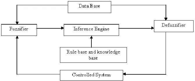
derive from the information available from the domain experts and/or observed control actions. The building of such rules and membership functions require tuning. That is, performance of the controller must be measured and the membership functions and rules adjusted based upon the performance. This process will be time consuming. The basic configuration of Fuzzy logic control based as shown in Fig. 4.1 consists of four main parts i.e. (i) Fuzzification, (ii) knowledge base, (iii) Inference Engine and (iv) Defuzzification.
Available online: https://edupediapublications.org/journals/index.php/IJR/ P a g e | 1777 1 Fuzzification:
Fuzzification maps from the crisp input space to fuzzy sets in certain, input universe of discourse. So for a specific input value x, it is mapped to the degree of membership A(x). The fuzzification
involves the following functions. Measures the value of input variables.
1. Performs a scale mapping that transfers the range of values of input variables into corresponding universe of discourse. 2. Performs the function of fuzzification that
converts input data into suitable linguistic variables, which may be viewed as labels of fuzzy sets.
The input variables to fuzzifier are the crisp controlled variables. Selection of the control variables relies on the nature of the system and its desired output. It is more common in the literature to use the output error and the derivative of output. Each of the fuzzy logic control (FLC) input and output signal is interpreted into a number of linguistic
variables. The number of linguistic variables specifies the quality of control which can be achieved using the fuzzy controller. As the number of linguistic variables increases, the computational time and required memory increases. Therefore a compromise between the quality of control and computational time is needed to choose the number is seven. Each linguistic variables NB, NM, NS, ZE, PS, PM, PB which stands for negative big, negative medium, negative small, zero positive small, positive medium, positive big respectively. For simplicity it is assumed that the membership functions are symmetrical and each one overlaps the adjacent functions by 50% i.e., triangle shaped function, the other type of functions used are trapezoidal -shaped and Bell-shaped. Figure 3.2 shows the seven linguistic variable and the triangular membership function with 50% overlap and the universe of discourse from – a to a.
Fi g 5 Tr i a ngul a r member s hi p func ti ons
2 Knowledge Base (KB):
Knowledge base comprises of the definitions of fuzzy MFs for the input and output variables and the necessary control rules, which specify the control action by using linguistic terms.
It consists of a database and linguistic control rule base.
1. The database provides necessary definitions, which are used to define linguistic control rules and fuzzy data, manipulation in a FLC.
2. The rule base characterizes the control goals and control policy of the domain experts by means of a set of a set of linguistic control rules.
3 Inference Mechanism:
The Decision – Making Logic Which plays an essential role and contains a set of fuzzy if-then rules such as
IF x is A and y is B then z is C
Where x, y and z are linguistic variables representing two input variables and one control output: A, B and C are linguistic values.
It is kernel of an FLC, it has the capability of simulating human decision making based on fuzzy control actions employing fuzzy implication and the rules of inference in fuzzy logic.
Available online: https://edupediapublications.org/journals/index.php/IJR/ P a g e | 1778 between input/output fuzzy sets. They are usually in
the form if A. (set of conditions are satisfied ) then B, (set of consequences can be inferred). Each rule defines a fuzzy path in the Cartesian product A x B (system state space). The antecedents of each fuzzy rule describe a fuzzy input region in the state space. For a system of two-control variable with seven linguistic variables in each range, this leads to a 7x7 decision table. The knowledge required to generate the fuzzy rules can be derived from an off – line simulation, an expert operator and/or a design engineer. Some knowledge can be used on the understanding of the dynamic system under control. A lot of effort has been devoted to the creation of the fuzzy rules. Normally rule definition is based on the operator’s experience and the engineer’s knowledge. However, it has been noticed in practice that for monotonic systems a symmetrical rule table is very appropriate, although some times it may need slight adjustment based on behavior of the specific system. If the system dynamics are not known or if the system is highly non – linear, trial and error procedure and experience play an important role in defining the rules.
4 Defuzzification:
Defuzzification converts the linguistic variables to determine numerical val ues. Centroid method of defuzzification is used in this study.
(1) A scale mapping, which converts the range of values of input variables into corresponding universe of discourse. (2) Defuzzification, which yields a
non-fuzzy control action from an inferred fuzzy control action.
We defuzzify the output distribution B to produce a single numerical output, a single value in the output universe of discourse Y = {y1, y2…yp}. The
information in the output waveform B resides largely in the relative values of membership degrees. The simplest deuzzificatioin scheme chooses that, element Ymax. That has maximal membership put in
the output fuzzy ser B. MB (ymax) = max mB (yj); 1 j
k
The maximum membership defuzzificatioin scheme has two fundamental problems. First, the mode of the B distribution is not unique. In practice B is often highly asymmetric; even if it is unimodal infinitely many output distributions can share the same mode. The maximum membership scheme ignores the information in much of the waveform B. The natural alternative is the fuzzy centroid defuzzificatioin scheme. The regions in which the control actions are overlapped depending upon their membership function. The area thus obtained is divided into narrow strips of equal width of each vertical line, the membership function and the corresponding point on the universe of discourse is evaluated. The centroid is calculated using the formula given below. The graphical representation of centriod is shown in Fig. below.
B= pj=1Yj mB (yj) / pj=1mB (yj)
5.5
Where mB(yj) = membership function of the jth strip.
yj = Corresponding Crisp value of jth strip. p = number
of strips.
Available online: https://edupediapublications.org/journals/index.php/IJR/ P a g e | 1779 This value is actually the deterministic input required
to regulate the process. The entire universe of discourse is then divided into seven triangles, equal in area, each representing the region of the linguistic variables as in fuzzification. The fuzzy centroid is
unique and uses all the information in the output distribution B. Computing the centroid is only step in the defuzzification process, which requires simple division.
VI.SIMLULATION RESULTS
A).EXISTING RESULTS
Fig 7.Circu it Diag ram
Available online: https://edupediapublications.org/journals/index.php/IJR/ P a g e | 1780 Fig 9. Rectifier Ou tp u t
Fig 10.To tal o u tp u t with -o u t filter
Fig 11. To tal o u tp u t with filter
Available online: https://edupediapublications.org/journals/index.php/IJR/ P a g e | 1781 Fig 12. M A TA LB/SIM ULINK d iag ram o f p ro p o s ed s y s tem
Fig 13. So u rce co n tro ller s u b s y s tem
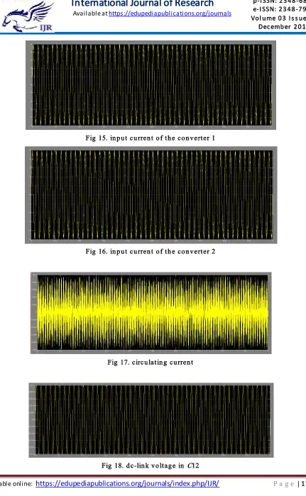
Available online: https://edupediapublications.org/journals/index.php/IJR/ P a g e | 1782 Fig 15. in p u t cu rren t o f th e co n v erter 1
Fig 16. in p u t cu rren t o f th e co n v erter 2
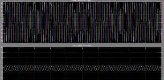
Fig 17. circu latin g cu rren t
Available online: https://edupediapublications.org/journals/index.php/IJR/ P a g e | 1783 Fig 19. lo ad cu rren ts
CONCLUSION
This project was proposed a single-phase to three-phase power conversion system with parallel rectifier and series inverter to cope with single-phase to three-phase asymmetry. Such converter guarantees both reduction in the input current processed by rectifier circuit and reduction of the output voltage processed by the inverter circuit. It is worth mentioning that, in spite of proposing a topology with features not yet observed on the technical literature, this paper presents a comprehensive model of the proposed converter, modulation strategy, and a general comparison with the conventional configuration. In extension we used fuzzy controller to controlling source side converter. And as well as it improve the wave shape and gives high accuracy compared to pid controller Simulated results are also presented.
REFERENCES
[1] A. H. Maggs, “Single-phase to three-phase conversion by the ferrarisarno system,” Electr. Eng.—Part I, General, J. Inst., vol. 93, no. 32, pp. 133–136, Aug. 1946.
[2] K. Hisano, H. Kobayashi, and T. Kobayashi, “A new type single-phase to three-phase converter,” IEEE Trans. Magn., vol. 2, no. 3, pp. 643–647, Sep. 1966.
[3] S. Dewan and M. Showleh, “A novel static single-to three-phase converter,” IEEE Trans. Magn., vol. 17, no. 6, pp. 3287–3289, Nov. 1981.
[4] M. Liserre, “Dr. Bimal K. Bose: A reference for generations [editor’s column],” IEEE Ind. Electron. Mag., vol. 3, no. 2, pp. 2–5, Jun. 2009. [5] F. Blaabjerg, A. Consoli, J. A. Ferreira, and J. D. van Wyk, “The future of electronic power processing and conversion,” IEEE Trans. Ind. Appl., vol. 41, no. 1, pp. 3–8, Jan./Feb. 2005. [6] F. W. Gutzwiller, “Thyristors and rectifier diodes-the semiconductor workhorses,” IEEE Spectrum, vol. 4, no. 8, pp. 102–111, Aug. 1967. [7] A. Elasser, M. H. Kheraluwala, M. Ghezzo, R. L. Steigerwald, N. A. Evers, J. Kretchmer, and T. P. Chow, “A comparative evaluation of new silicon carbide diodes and state-of-the-art
silicon diodes for power electronic
applications,” IEEE Trans. Indust. Appl., vol. 39, no. 4, pp. 915–921, Jul./Aug. 2003.
[8] M.-K. Nguyen, Y.-G. Jung, and Y.-C. Lim, “Single-phase AC–AC converter based on quasi-z-source topology,” IEEE Trans. Power Electron., vol. 25, no. 8, pp. 2200–2210, Aug. 2010.
Available online: https://edupediapublications.org/journals/index.php/IJR/ P a g e | 1784
AC converter,” IEEE Trans. Power Electron., vol. 27, no. 1, pp. 201–210, Jan. 2012.
[10] B. Saint, “Rural distribution system planning using smart grid technologies,” in Proc. Rural Electric Power Conf., Apr. 2009, pp. B3-1–B3-8.
[11] A. R. C. de Lima Montenegro Duarte, U. H. Bezerra,M. E. de Lima Tostes, and G. N. da Rocha Filho, “Alternative energy sources in the Amazon,” IEEE Power Energy Mag., vol. 5, no. 1, pp. 51–57, Jan./Feb. 2007.
[12] X.Wang, H. Zhong,Y.Yang, andX.Mu, “Study of a novel energy efficient single-phase induction motor with three series-connected windings and two capacitors,” IEEE Trans. Energy Convers., vol. 25, no. 2, pp. 433– 440, Jun. 2010.
[13] M. Khan, I. Husain, and Y. Sozer, “Integrated electric motor drive and power electronics for bidirectional power flow between the electric vehicle and DC or AC grid,” IEEE Trans. Power Electron., vol. 28, no. 12, pp. 5774–5783, Dec. 2013.
[14] Y.-S. Lai, W.-T. Lee, Y.-K. Lin, and J.-F. Tsai, “Integrated inverter/ converter circuit and control technique of motor drives with dualmode control for EV/HEV applications,” IEEE Trans. Power Electron., vol. 29, no. 3, pp. 1358–1365, Mar. 2014.