On the Implementation of RC Car for Exploration in Disaster Situation
Ye Hoon Lee
Department of Electronic and IT media Engineering, Seoul National University of Science & Technology, Seoul, 01811, Korea
Abstract
As concerns over social safety nets have increased in recent years, such as arson and earthquakes, the public's interest in and expectations for safety has increased. Based on these social trends, we design and implement a fire disaster RC car equipped with various sensors and cameras. The purpose of our work is to contribute to building a safer society by minimizing casualties and building a smart disaster management system at the disaster site. Internet of Things (IoT) technology is used as a way to control RC car, which include sensing technology for obtaining information from objects in the surrounding environments, wired and wireless communication and network technology for supporting objects to be connected to the Internet, and service interface technology for various service fields. And security technology is also necessary to prevent hacking or information leakage of the Internet component of a large amount of data and the like. The expected effect of the works is that the people directly enter and rescue the disaster sites such as fire and burial, and using this work, they are put in place at the disaster site and can grasp the internal situation more accurately and safely. With the smartphone or tablet PC in your hand, you can check the internal situation of the disaster scene in real time through the camera and sensor.
Keywords: Disaster, RC Car, Remote Control, Internet of Things, Interface Technology.
1. Introduction
The Internet of Things (IoT) is an advanced stage of the Internet or mobile Internet based on existing wired communication, and the devices connected to the Internet can exchange information with each other without any human intervention. The concept of IoT is similar to that of conventional ubiquitous and machine to machine (M2M) communications in that things do not depend on humans. It has evolved into a concept that interacts with all information of reality and virtual world as well as objects.
The IoT-based industry is a new playground that is still growing, and the development of technology is expected with business creation in many fields in the future. As a result, we try to gain a broad understanding of IoT technology, and to gain engineering achievement based on creative thinking about how this technology can change the quality of life and change the way of life. Flexibility of communication between objects and people who are in
trouble. Also, it becomes possible to simplify the process of information exchange and to communicate with objects through smart phone, enabling more active communication.
The issue of safety is now a very important one, and we can see the news of 'firefighter leaving' in the fire scene. Therefore, based on the IoT technology, the camera and the sensors are transmitted to the Android mobile through the Internet, so that the user can confirm the information and the user can access the Internet through the mobile and control the camera. This helps firefighters to understand the internal situation of the fire scene in a safer place in dangerous situations.
We implement an IoT-based fire-fighting RC Car. We want to check and control something in a remote place through a smart phone or a tablet PC in my hand. At first, we consider a simple RC Car, but in the process of designing a piece of work, we came up with an RC Car that could attach a variety of sensors and cameras to replace a dangerous place that people cannot enter. The expected effect of the works is that the people directly enter and rescue the disaster sites such as fire and burial, but using this work, they are put in place at the disaster site and can grasp the internal situation more accurately and safely. With the smartphone or tablet PC in your hand, you can check the internal situation of the disaster scene in real time through the camera and sensor. Therefore, it is expected to help diversify the channels of technology intensive small and medium sized safety companies, such as linking official development assistance (ODA) projects, in accordance with government policies that foster safety fields as new creative industries.
2. System Model
technology includes Android development environment and MCU development environment for mobile application, web service, and camera operation control. It is easy to control the RC Car to the required place with the smartphone in the hand, which makes it possible to handle efficient and safe work.
Fig. 1 System block diagram.
In addition to the internal image of the fire scene, sensors such as internal temperature, oxygen concentration in the air, etc. are attached to the RC car to provide mobility, so that the necessary information can be obtained in places where people cannot enter. In the course of designing a RC car for mobility, we selected a caterpillar-type tank model with a jaw or a flexible advantage in various obstacles. And the H/W and lines which can be seen as dirty are designed to have a two-layer structure and fixed on the first floor, making it look neat. The location of the camera was installed at the uppermost position so that it could be faithful to the purpose of confirming the image, and it was designed to complement the directional restriction of the RC car while moving up and down.
3. System Design and Implementation
3.1 Hardware Module
We used an open platform based on the Arduino Internet as the board to control the motor. Open source is open, software development is universal, sensor is easy to manipulate, and interoperability with various hardware devices is excellent. We programmed to move the motor up and down and left and right when receiving 4 signals using the Arduino sketch program. We used digital pins D10 and D9 as the PWM part in the schematic. The PWM-coded upper and lower signals are programmed to be transmitted to the external terminals through the output terminals D10 (upper and lower) and D9 (left and right). A0 pin is used to read the analog sensor value of the
carbon monoxide sensor, and the temperature value of the temperature sensor can be read using the SDA and SCL pins.
Fig. 2 Motor control whole circuit diagram.
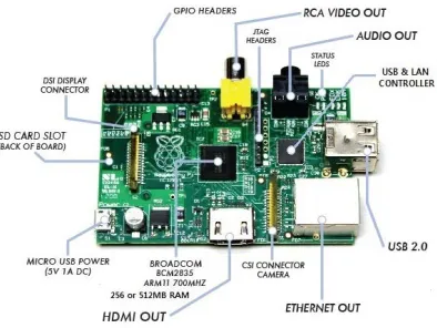
Fig. 3 Web server board outline drawing.
Raspberry Pie (Web Server Board) is a single board computer created by the British Raspberry Foundation to promote basic computer science education at school. Raspberry Pie uses Broadcom's BCM2835 single-chip system, which includes an ARM1176JZF-S 700MHz processor, a video core IV GPU and 256MB of RAM. Raspberry pie does not have a built-in hard disk drive or solid state drive, and uses an SD card as an external storage device. In addition, the Raspberry Pie Foundation provides Linux distributions of Debian, Arch Linux and QtonPi, which are ported to Raspberry Pie.
SN754410 motor driver shown in the middle of GPIO 4, 17, 27, and 22 pins has its own connection to VCC, GND, and port connected to motor, so it is designed to be driven by plugging only IC chip.
Fig. 4 Multi-pi coupled (left) and GPIO Pin layout (right).
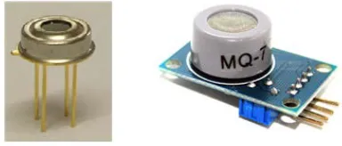
We use a sensor that can read the ambient temperature, the object temperature, and the carbon monoxide concentration. Carbon monoxide is chosen because it can be a huge risk to the human body. The LX9014 is a non-contact infrared temperature sensor that can measure both the temperature of the object and the ambient temperature. The ambient temperature can be read from -40 to 125 ° C and the object temperature can be read from -70 to 380 ° C. In the case of a carbon monoxide sensor, the basic operating principle is that the resistance changes when the carbon monoxide is combined with the catalyst, thereby changing the current flowing. The concentration of carbon monoxide is measured using the current change at this time. The unit is PPM.
Fig. 5 MLX90164 temperature sensor (left) and MQ-7 carbon monoxide sensor (right).
3.2 Software Algorithm
We program to move the motor up and down and left and right when we receive 4 signals using the Arduino sketch program, and we program the codes to read the values of the temperature sensor and the CO concentration sensor. Arduino supports the C and C++ languages as programming languages. By signaling the signal and the part declared for each signal, the motor is moved up and
down from 0 to 170 degrees. The reason why the angle is set to 30 to 170 is that the pan tilt structure supporting the servomotor is not completely assembled to 0 to 180 degrees, which gives a certain error in the system structure. We wrote the code to output the sensor value every 2 seconds.
Fig. 6 Wireless deployment completed (Web server environment).
Webiopi is a framework that allows you to work on Pi's IO on the Web as its name suggests. It is developed with HTTP, JavaScript, Python, etc., and provides easy-to-access libraries. Raspberry pie has GPIO port on the web and is open to the Google code site. There are many ways to control Raspberry Pie's GPIO, but we decided to use Webiopi for Web-based control. As the name suggests, Webiopi is designed to control the GPIO in the Web Browser, runs Web Server with Python, and designs Web pages with HTML and JavaScript. You can control the input/output pins of the web server board by controlling the GPIO with Python and calling the Python function with JavaScript.
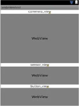
Fig. 7 Eclipse graphic layout
The above layout is a java xml file, and here are three java scripts written to display the WebView on the app screen. The WebView is coded by loading the url, and the JavaScript file loads MyChromeClient and WebBrowserClient in one main activity (Webview Activity) without having to create three separate activities. There will be three screens in the app. Camera information, sensor information, and button control information. It is enough to pop up the camera and sensor information on the screen, but the button control should not only bring up the address, but also make it possible to do the same thing that was possible to switch from the web to the camera and RC car.
4. Performance Test and Evaluation
In order to receive the signals for controlling the camera up/down/left/right on the web page, the connection between the MCU board and the web server board is performed. The servo motor is connected to the PWM terminals 10 and 9 of the Arduino, and the up/down/left/right signals are transmitted to the digital pins 3,4,5,7. This signal is received by the GPIO terminals 18, 23, 24 and 25 of the web server board, respectively, so that the signal can be transmitted to the web page through Webiopi. In case of sensor, temperature sensor and sensor for measuring carbon monoxide concentration are connected to SCL and A0 pins, respectively, and this value is sent to Raspberry Pi via serial communication.
We use the method of connecting the USB line directly by connecting the two boards. The signal from the GPIO
(input/output pin) of the web server board is connected to the input pin of the motor control board. It is necessary to lower the 5V to 3.3V due to the different voltages used to send signals from the Raspberry Pi board that builds the web server to the Arduino board that implements the motor control. However, Taduino, an updated version of Arduino, we do not have to add any additional circuitry.
Fig. 8 Connection between Web server board and MCU.
Fig. 9 Appearance of RC car side system and client system.
However, there are wireless routers that support port forwarding and unsupported wireless routers, and neither of the two routers we provide supports port forwarding, so we cannot implement them.
4. Conclusions
In this paper, we succeeded in moving and controlling the camera and RC car by using the mobile application. It is almost completely implemented with the initial goals that were aimed before production of control and communication, sensor and external robustness. Basically, it is a work with the function that was made for the purpose of using fire-fighting, but there is a possibility of development and it can be used for various purposes. We used mjpg-streamer to experiment with various programs, camera with low latency and stable image streaming, but it would be better to use motion or open CV programs when considering camera for various purposes. We expect that our work is used not only in the works developed so far but also in various fields beyond the fire scene.
Basically, our work was produced by IoT method, so anyone can easily control the object where one needs with smart phone in the hand, so energy conservation and high efficiency work can be done. Before it is used for the purpose of fire-fighting use, our work can build a system with low power through linkage with the power on-off system, thus saving standby power and convenience of real life. This work is optimized for a fire scene, and it has special features such as an installed cooler and an atmospheric CO concentration sensor, so it will be possible to obtain information by directly controlling a fire scene that cannot be reached by a smart phone.
Acknowledgments
This study was supported by the Research Program funded by the Seoul National University of Science and Technology (2016-1697).
References
[1] C. Pfister, Getting Started with the Internet of Things, CA: O’Reilly Media, 2011.
[2] D. G. You, J. M. Park, Android API Bible, Information Culture History, 2010.
[3] D. Lee, The Web App Programming with HTML5 and Phone Gap, PC Books, 2012.
[4] M. Margolis, Arduino Cookbook, 2nd Ed., O’Reilly Media, 2012.