Design and Development of Rectangular Patch
Antenna for WLAN Applications
K. Kanaka Madhuri1, A. Sudhakar2
M. Tech Student [CESP], Dept. of ECE, RVR & JC College of Engineering, Guntur, Andhra Pradesh, India1
Professor, Dept. of ECE, RVR & JC College of Engineering, Guntur, Andhra Pradesh, India2
ABSTRACT: In this paper, the rectangular patch antenna is designed for WLAN applications. It describes the performance analysis of different feeding techniques of microstrip patch antenna (3-6GHz). Two types of feeding technique “Microstrip line feed, coaxial probe feed” are used. The microstrip line and coaxial probe feed are contacting schemes, in which RF power is feed directly to the radiating patch using a connecting element such as a microstrip line where as proximity and aperture coupled feeds are non-contacting schemes, in which electromagnetic field coupling is done to transfer power between the microstrip line and the radiating patch. Rectangular patch antenna gives better design parameters such as reflection coefficient, band width, VSWR, directivity and resonant frequency. The rectangular patch antenna is simulated with the help of CST software.
KEYWORDS: Rectangular patch antenna, microstrip line feed, coaxial probe feed, reflection coefficient, bandwidth, directivity, resonant frequency, CST.
I.INTRODUCTION
Microstrip antennas have recently received much attention and are used as efficient radiators in many communication systems. There is an increase in demand for microstrip antennas [1] with improved performance for wireless communication applications are widely used for this purpose because of their planar structure, low profile, light weight, moderate efficiency and ease of integration with active devices [2].
The antenna is the basic element on these communication systems, it is a key component in system performance and size, and it has to simultaneously satisfy three classes of requirements [3]. i) Geometrical characteristics (small size, light weight, adaptability to actual platform, and non obstructive to the user), ii) Electrical performance (wide bandwidth, radiation properties, high efficiency), and iii) Manufacturing constraints (low cost, reliability, packaging capabilities).
Wireless communications continues to enjoy exponential growth in the cellular telephony, wireless networks include wireless local area network (WLAN) [4] for which the IEEE 802.11 group has the responsibility for setting the standards [5-11].
II. ANALYSIS OF MICROSTRIP PATCH ANTENNA
The resonance frequency depends on the patch size, cavity dimensions, and the filling material dielectric constant. It is expressed as follows;
=
2 √
Where m, n= 0, 1, 2… = wave number at m, n mode, c is the velocity of light, is the dielectric constant of substrate, [12-13] and
= +
Length and width of non radiating rectangular patch’s edge at a certain resonance frequency and dielectric constant are given by:
=
and
= 2
+ 1
Where f is the resonance frequency at which the rectangular microstrip antenna is to be designed. The radiating edge w, patch width is usually kept such that it lies within the range L<W>2L for efficient radiation. By using the above equations we can find the value of actual length of the patch as:
=
2 −2∆l
Where the effective dielectric constant and ∆l is the line extension which is given as
ε = ε + 1
2 +
ε + 1
2 .
1
1 + 12wh
∆l
h = 0.412
(ε + 0.3) wh + 0.264
(ε −0.258) wh + 0.8
III. MICROSTRIP LINE FEED ANTENNA DESIGN PARAMETERS
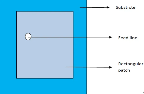
The microstrip line feed antenna is shows in figure 1. It consists of a printed rectangular patch antenna on FR4 substrate of thickness 0.8mm and a relative permittivity 4.4. The substrate has a length of L=20mm and the width of W=15 mm. The dimensions of the partial conducting ground plane are 15mm x 7mm. The excitation is launched through a50 Ohm microstrip feed line, which has the length 7.8mm and the width 1.5mm.
The dimensions of all part of the microstrip line fed antenna are given in table 1.
Substrate 15mm x 20mm x 0.8mm
Ground plane 15mm x 7mm
Rectangular patch 7mm x 8mm
Rectangular slot 3mm x 6mm
Step 3mm x 2.2mm
Feed line 1.5mm x 7.8mm
Table 1.Dimensions of all parts of the line feed antenna
IV. SIMULATION RESULTS
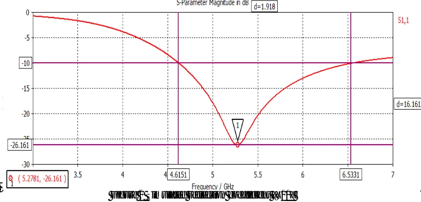
Simulation studies of microstrip line feed antenna reported here are carried out using CST Microwave studio [14]. Figure 2 shows the simulated reflection coefficient [ ] of the microstrip line feed antenna in dB. Gives the reflection coefficient at port 1 where we apply the input to the microstrip patch antenna. It should be less than -10dB for the acceptable operation. It shows that the microstrip line feed antenna resonates at frequency equal to 5.27 GHz which gives the measure of the wide band characteristic of the patch antenna. The simulated impedance band width of about 191.8MHz (4.6151-6.5331) is achieved at -10dB reflection coefficient. The reflection coefficient value that is achieved at this resonant frequency is equal to -26.161dB. This reflection coefficient value suggests that there is good matching at the frequency point below the -10dB region.
Figure 2 Simulated reflection coefficient [S11]
Radiation pattern is a graphical depiction of the relative field strength transmitted from or received by the antenna. The antenna should not have the side lobes ideally. We cannot remove them completely but we can minimize them. Figure 3 shows the simulated 3-D radiation pattern with directivity of 2.585dBi for microstrip line feed antenna configuration at the resonating frequency of 5.27GHz.
Figure 3.3D Radiation pattern for = 5.27GHz
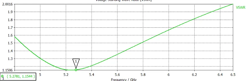
Figure 4 Shows the VSWR (voltage standing wave ratio) plot for the designed antenna. The value of VSWR should lie between 1 and 2. SWR is used as an efficiency measure for transmission lines, electrical cables that conduct radio frequency signals, used for microstrip line feed such as connecting radio transmitters and receivers with their antennas, and distributing cable television signals. Here the value of the VSWR for the microstrip line feed antenna is1.15 at the specified resonating frequency.
Figure 5.VSWR plot for the microstrip line feed antenna
V. FABRICATED ANTENNA
The front and back using of the designed and fabricated microstrip line feed antenna is given in the figure 6. The testing of antenna can be done by using Vector Network Analyzer.
VI. COAXIAL PROBE FEED ANTENNA DESIGN PARAMETERS
Figure 7 shows the geometry of coaxial feed microstrip patch antenna with single band operation for WLAN application. The antenna is excited by coaxial feed line designed for a 50 Ohm characteristic impedance and is printed on substrate with a thickness of 1.5748mm, dielectric constant of 2.5 and loss tangent of 0.0009.
Figure7. Geometry of the coaxial probe feed antenna
The height of the ground which is beneath the substrate and made of PEC material is taken to be three times the thickness of substrate for simulation purpose i.e. 3 x 1.5748mm and of the patch which is also made of material PEC (Perfect Electric Conductor) is 0.02mm. The outer conductor (from bottom of ground to top of ground) is made of substrate material and inner conductor (from bottom of ground to top of patch) is made of PEC material. The inner and outer radius of coaxial probe is 1.25 mm and 4.6 mm respectively. The feed point for the coaxial feed antenna is found to be (-4.25, 0) where the best impedance matching of 49.5 Ohm has been achieved which is very close to50 Ohm.
The dimensions of all part of the coaxial probe feed antenna are given in table 2.
Substrate 54mm x 62mm
Rectangular patch 32mm x 42mm
Ground 54mm x 62mm
VII. SIMULATION RESULTS
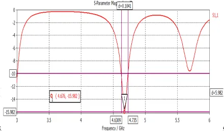
Figure 8 shows that the coaxial feed antenna resonates at frequency equal to 4.676GHz which gives the measure of the wideband characteristic of the patch antenna. The simulated impedance bandwidth of about 104.1MHz (4.63-4.73GHz) is achieved at -10dB reflection coefficient (VSWR ≤ 2). The reflection coefficient value that is achieved at this resonant frequency is equal to -15.982dB.
Figure8. Simulated reflection coefficient [S11]
Figure 9 shows the simulated 3-D radiation pattern with directivity of 8.128dBi for coaxial feed antenna configuration at the resonating frequency of 4.676 GHz.
Figure 10 shows the VSWR plot for the designed antenna. The value of VSWR should lie between 1 and 2.The value of the VSWR for the coaxial feed microstrip patch antenna is 1.37 at the specified resonating frequency.
Figure 10 VSWR plot for the coaxial feed antenna
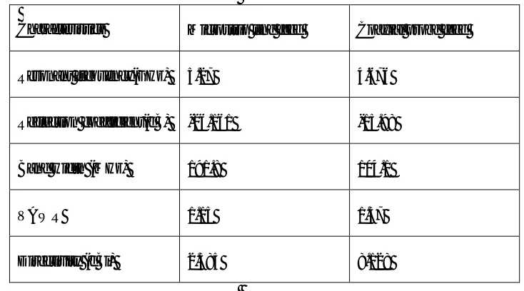
Table 3 Comparisons of two types of feeding techniques
Characteristics Microstrip line feed Coaxial probe feed
Resonant frequency(GHz) 5.27 4.676
Reflection coefficient(dB) -26.161 -15.98
Band width (MHz) 191.8 104.1
VAWR 1.15 1.37
Directivity (dBi) 2.585 8.128
VIII. FABRICATED ANTENNA
Figure11. Front and back view of fabricated antenna
IX.CONCLUSION
The optimum results of two different feeding techniques of rectangular patch antenna on FR4 and RT5880 substrate for WLAN applications has been investigated. A comparison is made between two feeding techniques in terms of bandwidth, reflection coefficient, VAWR and directivity. The microstrip line feed antenna exhibits a bandwidth of about 190.96MHz (4.61-6.53GHz) at -10dB reflection coefficient which corresponds to 5.27GHz WLAN standard. The maximum achievable directivity is 2.585dBi with the corresponding reflection coefficient of -26.161db. A simple coaxial feed microstrip patch antenna in 4.676GHzWLAN frequency band has been demonstrated and implemented using CST microwave studio software. This antenna exhibits a narrow bandwidth of about 104.1MHz (4.6-4.7GHz). The maximum achievable directivity is 8.128dB with the corresponding reflection coefficient of -15.98dB. So, it is observed that the bandwidth of microstrip line feeding is better than coaxial probe feeding.
REFERENCES
[1] Deschamps, G.A., “ Microstrip Microwave Antenna,” Third symposium on the USAF Antenna Research and Development program, University of IIIinois, Moticello, IIIinois, October 18-22, 1953 .
[2] M. Ali, T. Sittironnarit, H.S. Hwang, R. A. Sadler, and G.J.Hayes,“Wide-Band/Dual- Band Packaged Antenna For 5-6 GHz WLAN Application,” IEEE Trans. Antennas Propagat ., vol.52 , N.2. pp . 610-615, February. 2004.
[3] L. Jofer, B. A. Cetiner, and F.Flaviis,“Miniature Muitielement Antenna for Wireless Communication,” IEEE Trans. Antennas Propag. vol.50, N. 5. pp . 658-669, May 2002.
[4] R. Jordan and C. T. Abdallah, “ Wireless communications and networking: An overview,” IEEE Antennas Propag. Mag., vol. 44, pp. 185-193, Feb.2002.
[5] I-F. Chen, C. M. Peng,and S- C. Liang, “ Single Layer Printed Monopole Antenna for Dual ISM-Band Operation,” IEEE Trans. Antennas Propagat.,vol.53, N. 4. pp. 1270-1273, April.2005.
[6] Y. Ge, K. P. Esselle, and T.S. Bird, “ E-Shaped Patch Antennas for High-Speed Wireless Networks,” IEEE Trans. Antennas Propagat., vol.52, N. 12. Pp. 3213-3219, December.2004.
[7] Jun-Hai Cui, Shun-Shi Zhong, “ Compact microstrip patch antenna with C-shaped slot” Microwave Conference, Asia- pacific, 2000. [8] N.A. Murad, M.Esa and S. Tukachil, “ Microstrip U-Shaped Dual-Band Antenna” Asai- Pacific conference on Applied Electromagnetics proceedings,2005.
[9] K.Kumar andN.Gunasekaran, “ A Novel Wide Band Planar n Shaped Base StationAntenna” International Conference on Communications and Signal Processing (ICCSP), 2011.
[10] J. Kaur, R. Khanna and M. Kartikeyan, “Design of co-axial fed broadband single layer rectangular microstrip patch antenna for wireless Applications” J,Engg. Technol., vol.3, No. 2, pp. 71-75, 2013.
[11] R.Garg, P. Bhartia, I.Bahl and A.I tipiboon, “ Microstrip antenna design handbook ”, Artech House, Boston-London, 2000. [12] Global Journal of Research Engineering Volume 11Issue 2 Version 1.0 March 2011 ISSN 0975-58.