Space Vector Pulse Width Amplitude
Modulation for a VSI Fed Induction Motor
Drive
Surasmi N L1, Swetha C2
Assistant Professor, Dept. of EEE, Mar Baselios College of Engineering and Technology, Thiruvananthapuram, Kerala,
India1
PG Scholar, Dept. of EEE, Mar Baselios College of Engineering and Technology, Thiruvananthapuram, Kerala, India 2
ABSTRACT:This paper proposes a converter -inverter fed induction motor drive which can be used in plug in hybrid electric vehicle or electric vehicle. The advantage of this PWM technique is that by eliminating the zero vectors the
switching loss can be reduced. By maintaining a 6ω varied dc link voltage reduced dc link capacitor decreases the size
of the system which can increase the power density. The simulation of the system has been done using MATLAB/SIMULINK. It can be seen that the THD is relatively less. It is feasible for applications which require high efficiency, high power density, low cost. The theoretical analysis for switching loss calculation is also derived.
KEYWORDS:SVPWAM, Induction motor, 6ω dc link voltage, Switching loss reduction, FFT analysis
I.INTRODUCTION
Plug in hybrid electric vehicles (PHEV) makes use of both conventional fuel and electric energy which is stored in the battery. Utilizing electricity from the grid for charging the battery costs less and reduces fuel consumption compared to conventional vehicles. These vehicles can also reduce emissions depending on the electricity source. A Bidirectional dc-dc converter serves the purpose of stepping up or stepping down the voltage level between its input and output along with the capability of power flow. They have applications in the area of energy storage systems for hybrid vehicles, renewable energy storage systems and fuel cell storage systems. The general block diagram is shown in figure 1.
Fig 1Block diagram of the system
PHEV consists of converter, inverter and motor which use energy stored in a battery. The batteries in PHEV can be charged in several ways that is by an outside electric power source, by the internal combustion engine or else by regenerative braking. A battery is used to store the electrical energy which powers the motor. These vehicles require less maintenance due to few moving parts.
number of switching instances up to one-third of fundamental period. But it causes unwanted stress in the power semiconductor devices. A method similar to SVPWAM technique is seen in [14] which reduce the averageswitching frequency by a factor of three to reduce the switching power loss.
In this paper space vector pulse width amplitude modulation (SVPWAM) method for a voltage source inverter fed
Induction motor drive with 6ω varied dc link voltage is implemented by using MATLAB/SIMULINK. The simulations
have been done for a 2HP Induction motor. The advantages of using Induction motor in electric vehicle are also discussed. The theoretical analysis for switching loss calculation is done to verify the improvement in efficiency. FFT analysis had been done for the whole system and was seen to be 4.57%.
II.SVPWAM METHOD
A. Operating Principle
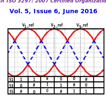
Space vector pulse width modulation (SVPWM) is a special switching sequence of the upper three switches of a three phase inverter. It has advantages like less harmonic distortion in the output voltages which are applied to the phases of an AC motor and to provide more efficient use of supply voltage compared with sinusoidal modulation technique. Among the eight possible switching states for which two of them are zero vectors and six of them are active switching states. The conventional zero vectors are eliminated in each sector in Space vector pulse width amplitude modulation technique thus Vref will be at its maximum amplitude. Thus SVPWAM method is a combination of amplitude
modulation and pulse width modulation such that each inverter leg is switched during one third of fundamental period. The modulation principle of SVPWAM is shown in figure 2.The voltage vectors only follow the sides of the hexagon. As zero vector are not utilized during each sector two switches and their complementary switches does not change its state and thus only one pair of switches need to do PWM switching.
Fig 2.Representation of inverter states
Fig. 3 Switching pattern for SVPWAM method
Compared to conventional SVPWM technique the vector placement is also changed which does not have a transition to zero vector time period. The vector placement within one switching cycle in each sector is shown in figure 4. The new time period [1] can be calculated as:
=
Where the time periods T1 and T2 are
Fig 4 Vector placement diagram
B. Inverter switching loss Calculations
The inverter switching loss per IGBT from [15] using conventional sinusoidal PWM in the inverter system is: 60
sin ) 60 sin(
1
d
s ref
V
T v
T
60 sin sin
2
d s ref
V T v
T
(1)
(2)
, = ′ ′ (6)
Where is= Issinωt
So the switching loss of each IGBT can be represented as
_ = [
,
+ ′ ′, ]
Under unit power factor condition the SVPWAM has switching in two 60° sections thus the integration over 2 is limited down within two 60°. So the switching action is taken during the periods ( , ) and ( , ).
The switching losses are given by:
_ = [ ( ) + ( )] [∫ sin( )dωt] + [∫ sin( )dωt] (8)
= √ [ , + ′ ′, ]
Thus switching loss of SVPWAM method is calculated by
_ _
=2− √3
2
=13.4% compared to conventional sinusoidal PWM method
III. BUCKBOOST CONVERTER
A converter is present at the front end for energy flow from battery to the dc link and from dc link to battery. The unidirectional dc/dc converter can be replaced by diodes with controllable switches as individually buck converter and boost converter do not have bidirectional power flow capability. By operating the switches both buck and boost operations are possible. The bidirectional switches carries current in both directions and thus double sided power flow occurs. Generally IGBT or MOSFET are used in parallel with diode.
Here a 6ω varied feature is to be present at the dc link. In SVPWAM control, dc-link voltage has to vary with a voltage ripple whose frequency is six times of output frequency. This kind of ripple is called 6ω. [21] The peaks of the ripple are corresponding to the peaks of output three phase line-to-line voltage. The converter generates this ripple. This is the input to the inverter with SVPWAM. This provides nearly sinusoidal variation in the output voltage and the percentage in THD can be reduced. Another added advantage is that the size of dc link capacitor can be reduced. Thus the size of the system can be reduced which increases the power density.
IV.INDUCTION MOTOR
The induction motor is well suited for hybrid electric vehicle application because of its robustness, low maintenance, low price and reliability. Recently a new induction motor technology has been developed [22] for vehicle application which can produce the torque of a permanent magnet motor without using permanent magnet material. It also includes features like reduced manufacturing costs and operation of higher temperature and higher speed.
The power circuit diagram of Induction motor is shown in figure 5. The most popular motor model is the Krause’s model from which the flux linkage equations are given by [23]:
Fig 5 Inverter fed Induction motor drive
= [ − + + ]
= [ + + ( + )]
= [ − + − ]
(10)
= [ + + ( − )]
The electrical output torque equations are given by:
= ( − )
− =
Where Fij is the flux linkage
Fmq, Fmd are magnetizing flux linkage
Vqs, Vds d and q axis stator voltages
Vqr, Vdr d and q axis rotor voltages
ωe stator angular electrical frequency
ωe motor angular electrical base frequency
ωr rotor angular electrical speed
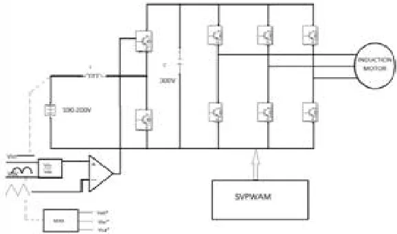
The circuit diagram for the system and control circuitry for the converter is shown in figure 6.
Fig 6 Converter Inverter fed Induction motor drive system
(11)
Rated Speed 1450 rpm
Frequency 50 Hz
Rated power 2HP
Reference Frame Stationary
Poles 4
Rs 0.435 Ω
Rr 0.816 Ω
Lls =Llr 2e-3 H
Lm 8e-3 H
J, Moment of inertia 0.089
V. SIMULATION RESULTS
The simulation results for SVPWAM for a voltage source inverter fed Induction motor has been simulated using MATLAB/SIMULINK. The dc input to the inverter is controlled by the bidirectional dc/dc converter through the
control circuitry by which a 6ω varied voltage is generated. The following waveforms were obtained. The simulation parameters are Vin =100V, L=1mH, C=2μF, fs=10kHz.
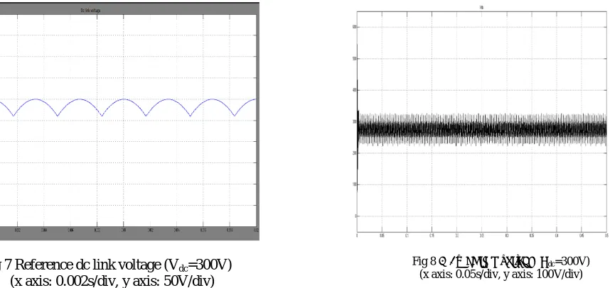
The reference dc link voltage given to the converter with Vdc=300V is shown in figure 7. The output of the dc-dc
converter by applying certain control in the input side is obtained where the voltage at the output of dc/dc converter as shown in figure 8.
Fig 7 Reference dc link voltage (Vdc=300V)
(x axis: 0.002s/div, y axis: 50V/div)
The switching pulses for the inverter are shown in figure 9 where we can see the number of switching’s reduced as the zero vectors are eliminated. The line voltage has nearly sinusoidal variation as shown in figure10 where the magnitude of voltage is 300V.
Fig 9 Switching pulses for SVPWAM method (x axis: 0.1s/div, y axis: 5V/div)
The speed response and the torque response of the machine are shown in figure 11 -12 where the speed response is almost steady and torque will less ripples. The torque waveform settles at a load torque of 2Nm. The speed waveform settles at its reference speed at 314rad/sec.
Fig 12 Speed waveform for SVPWAM inverter fed motor drive(x axis: 0.1s/div, y axis: 50rad/s/div)
VI. FFT ANALYSIS
By using FFT analysis overall THD of the output voltage is calculated. THD stands for Total Harmonic Distortion which is often used to define the degree of harmonic content in an alternating signal. Also keeping low THD values on a system will ensure proper operation of equipment and a longer equipment life span. In the case of SVPWAM the modulation index is always kept at its maximum value. When FFT analysis is done for converter - inverter fed Induction motor drive system it was found to be 4.57% as shown in figure 13.
Fig 10 Line voltage for the inverter Vin = 100 V, Vdc avg = 300 V, Po = 1 HP, fo = 50 Hz, fs = 10 kHz.
(x axis: 0.15s/div, y axis: 200V/div)
Fig 11 Torque waveform for SVPWAM inverter fed motor drive for a load torque of 2Nm
losses. Theoretical analysis is done for the switching losses and found as less. Efficiency of system can be improved with close loop control. Also a plug in hybrid vehicle that has solar array to recharge can be developed with reduced losses.
REFERENCES
[1] Qin Lei, Fang Zheng Peng, “Space Vector Pulse width Amplitude Modulation for a Buck–Boost Voltage/Current Source Inverter, ”IEEE Transc., Vol. 29, no. 1, pp.266-274, Jan 2014.
[2] D. M. Divan , G. Skibinski, “Zero-switching-loss inverters for high power applications,” IEEE Trans. Ind. Appl., Vol. 25, no. 4, pp. 634–643, Jul./Aug. 1989.
[3] W. McMurray, “Resonant snubbers with auxiliary switches,” IEEE Trans. Ind. Appl., Vol. 29, no. 2, pp. 355–362, Mar./Apr. 1993.
[4] J. S. Lai, R. W. Young, Sr. G. W. Ott, Jr. J. W. McKeever, and F. Z. Peng, “A delta-configured auxiliary resonant snubber inverter,” IEEE Trans. Ind. Appl., Vol. 32, no. 3, pp. 518–525, May/Jun. 1996.
[5] J. S. Kim and S. K. Sul, “New control scheme for ac-dc-ac converter without dc link electrolytic capacitor,” in Proc. 24th Annu. IEEE Power Electron. Spec. Conf., pp. 300–306, Jun. 1993.
[6] K. Rigbers, S. Thomas, U. Boke, and R. W. De Doncker, “Behavior and loss modeling of a three-phase resonant pole inverter operating with 120°A double flattop modulation,” in Proc. 41st IAS Annu. Meeting IEEE Ind Appl. Conf., Vol. 4, pp. 1694–1701, Oct. 8–12, 2006.
[7] H. Haga, K. Nishiya, S. Kondo, and K. Ohishi, “High power factor control of electrolytic capacitor less current-fed single-phase to three-phase power converter,” in Proc. Int. Power Electron. Conf., pp.443– 448, Jun. 21–24, 2010.
[8] X.Chen and M. Kazerani, “Space vector modulation control of an ac-dc-ac converter with a front-end diode rectifier and reduced dc-link capacitor,” IEEE Trans. Power Electron., vol. 21, no. 5, pp. 1470–1478, Sep. 2006.
[9] M. Hinkkanen and J. Luomi, “Induction motor drives equipped with diode rectifier and small dc-link capacitance,” IEEE Trans. Ind. Electron., Vol. 55, no. 1, pp. 312–320, Jan. 2008.
[10] J. Jung, S. Lim, and K. Nam, “A feedback linearizing control scheme for a PWM converter-inverter having a very small dc-link capacitor,” IEEE Trans. Ind. Appl., Vol. 35, no. 5, pp. 1124–1131 , Sep./Oct. 1999.
[11] L. Malesani, L. Rossetto, P. Tenti, and P. Tomasin, “AC/DC/AC PWM converter with reduced energy storage in the dc link,” IEEE Trans. Ind. Appl., Vol. 31, no. 2, pp. 287–292, Mar./Apr. 1995.
[12] F. Blaabjerg, S. Freysson, H.-H. Hansen, and S. Hansen, “A new optimized space-vector modulation strategy for a component minimized voltage source inverter,” IEEE Trans. Power Electron., Vol. 12, no. 4, pp. 704–714, Jul. 1997.
[13] L. Asiminoaei, P. Rodriguez, and F. Blaabjerg, “Application of discontinuous PWM modulation in active power filters,” IEEE Trans. Power Electron., vol. 23, no. 4,pp. 1692–1706, Jul. 2008.
[14] H. Fujita, “Switching loss analysis of a three-phase solar power conditioner using a single-phase PWM control method, ” in Energy Conversion Congress and Exposition(ECCE), pp. 618- 623, 2010.
[15] Datasheet: Powerex Duel-in-line intelligent power module 10 Amperes/600 Volts.
[16] Yi Huang, Chunquan Li “Model and system simulation of Brushless DC motor based on SVPWM control” 2nd International Conference on Electronic & Mechanical Engineering and Information Technology (EMEIT-2012).
[17] J. Holtz, “Pulse width modulation – A Survey”, IEEE Transactions on Industrial Electronics, Vol. 30, No.5, pp. 410-420, Dec 1992.
[18] H. W. V. D. Brocker, H. C. Skudenly and G. Stanke, “Analysis and realization of a pulse width modulator based on the voltage space vectors,” in Conf. Rec. IEEE-IAS Annu. Meeting, Denver, CO, pp. 244–251, 1986.
[19] Dorin O. Neacsu, “Space Vector Modulation–an introduction,” The 27th annual conference of the IEEE industrial electronics society.
[20] Keliang Zhou, and Danwei Wang, “Relationship between space vector modulation and three phase carrier- based PWM: A Comprehensive Analysis”, IEEE Transactions on Industrial Electronics, Vol. 49, No.1, pp.186-196 February 2002.
[21] Xianhao Yu, Qin Lei, Fang Zheng Peng, "Boost converter -inverter system using PWAM for HEV/EV motor drive," in 2012 Twenty-Seventh Annual IEEE Applied Power Electronics Conference and Exposition (APEC), pp.946-950 5-9 Feb. 2012.
[22] Mounir Zeraoulia, Mohamed Benbouzid, Demba Diallo. “Electric Motor Drive Selection Issues for HEV Propulsion Systems: A Comparative Study”, IEEE VPPC’05, Sep 2005, Chicago, United States. pp. 280-287, 2005.