Autonomous Guidance Vehicle with Obstacle
Detection and Avoidance
Sohini Aich1, Dr.H Prasanna Kumar2
PG Scholar [C&I], Dept. of EE, UVCE, Bangalore, Karnataka, India1
Assistant Professor, Dept. of EE, UVCE, Bangalore, Karnataka, India2
ABSTRACT: In order to allow hospital staff to spend a bigger part of their time with actual patients, this paper has focused on how to implement an autonomous robot to do some of their work. The robot is made to navigate in a hospital environment to perform some basic functions as well as avoiding obstacles and humans. The solution this paper presents is a multi-sensor system which is able to navigate through an unknown environment without hitting any obstacles whilst maintaining a certain heading. Analog distance sensors, motion sensor for vehicles’ orientation and velocity and a camera for location identification have been implemented .The LabView program enables the mobile robot to travel from a starting point to a user desired destination point, avoiding undefined obstacles on its route. This paper explores the scope to the robotics “Sense, Think and Act” approach where the robot senses for random obstacles on its path via an ultrasonic sensor, makes a decision based on a non colliding threshold distance in order to execute collision avoidance routine and returns to the process of reaching the predefined destination point. The PID controller is implemented to constantly maintain a threshold distance with the obstacle to control the speed of the vehicle and to avoid collision with the obstacles.
KEYWORDS: Navigation, Obstacle avoidance, Camera, Ultrasonic sensor, PID controller, LabVIEW
I.INTRODUCTION
Robotics has become one of the essential segments of modern automation systems. Autonomous mobile robots are being used in various industrial and non-industrial applications for the ease of human labor in day to day activities. Mobile robotics is a growing part in the robotics field, which is becoming progressively more important, useful, and common place in modern society. The only reason being that it is providing the fast functionality, mobility and various multi-media possibilities in different areas of Day to day life like at homes, work, public environments and remote locations where human reach is difficult like various remote locations such as space and deep sea , they are being employed not only in industry but also in service-oriented applications. The ability of mobile robots to perform a significantly extended range of tasks and services many locations offer a great request for specialized applications that lead to increase the interest in mobile robots. This leads to increase the interest in mobile robots.
The idea for this paper came from the hospitals, where there is a constant shortage of skilled staffs plus being understaffed with employees. There has been many steps taken in past to reduce the work load and to aid the staffs in their work. Studies have shown that only 30% of hospital staff's work involves actual patient-related tasks. To do a bed transport in any health care facility today requires two members of staff doing the transportation. An improvement in transportation efficiency would improve the time spent with actual patient care since it would reduce the amount of labour and time spent on moving by staff. Since a completely automated transport would possibly risk patient’s safety, it is important to point out that only one of the two staff members would be replaced in this kind of implementation will be safe.
The main aim of the project is to design, develop and implement the intelligent guidance vehicle which can be used to transport the bed to the desired location along with the obstacle detection and avoidance. The PID controller is implemented to constantly maintain a threshold distance with the obstacle to control the speed of the vehicle and to avoid collision with the obstacles. The guidance vehicle developed in the following project is using a colour following scheme to provide emergency services to the patient where the guidance vehicle is used for the purpose of the transportation of the bed from the ambulance to the ICU without the need of two staffs and automatically detect the path by avoiding the obstacles on its way and to reach its destined location.
.
III.BRIEF OVERVIEW OF SYSTEM
The entire process of autonomous guidance vehicle for the purpose of guidance of the hospital bed is divided into two parts. First the part deals with the development of the colour following module as the system we are trying to develop is fully automated and due to the sensitivity of the hospital environment which already consists of many electromagnetic waves , the system set up is avoiding the use of GPS and GSM tracking device for moving from source to destination. Secondly, the part deals with the path planning, how the guidance vehicle is reaching the desired destination without human assistance and avoiding the obstacles on the path.
Under the developed block diagram the ultrasonic sensors along with the MPU 6050 sensor are interfaced with Arduino Mega 2560 and Arduino Uno and the micro-controller Arduino is responsible for receiving all the raw data from the mounted sensors like ultrasonic sensors gives the distance of the approaching obstacles along the various directions of the vehicle and the MPU6050 provides the certain position of the vehicle so that it can be tracked by its co-ordinates. Now, depending upon the raw data received by the arduino commands the motor driver circuit which is interconnected to four DC motors to take the directions according to the approaching obstacles on the path that is either to move forward etc .The motion control is performed by the driver circuit commanded by the microcontroller.
Fig.1:- Block Diagram of Autonomous Guidance Vehicle
The experimental procedure of the process is explained and the working steps involved in building the autonomous guidance vehicle are discussed in brief.
FLOWCHART FOR THE COLOUR FOLLOWING
Color following technique developed as it has already been assumed that the emergency services of bed transportation till the ICU path is following a definite floor colour here ,it is assumed to be white floor which is maintained at certain intensity such that the colour intensity is not effected either at day or night time. The camera fixed must be able to detect the colour intensity at all times of the day.
The flowchart is as follows:-
Fig.2:-The Colour Following Approach
FLOWCHART FOR THE OBSTACLE AVOIDANCE
Now after the colour identification of the floor, the navigation towards the destination begins which will detect and avoid the obstacles on the path towards the destination. The obstacle avoidance algorithm developed consists of 4 ultrasonic sensors which will detect the obstacles on the following conditions as follows:-
The entire description is divided into two parts: one for the wireless communication to be setup with the camera while the other one is for automatic movement control. The Brief description is as follows:-
The establishment of connection with camera and the colour detection
For initializing the colour detection scheme the camera needs to be initialized. For the initialization of the camera the wifi environment is used due to mobility purpose as the USB based camera comes up with a problem of always getting wired to USB module. The IP webcam app is used for the camera initialization purpose where the camera is placed on the holder and the IP address of the environment is matched with the IP address of the mobile camera and the reception of the images is done easily.
The following image shows the step for matching the IP address:-
Fig.4:- Connecting the mobile camera For movement control
For the path planning scheme the obstacle detection and avoidance scheme has been developed .Here, the guidance vehicle will always maintain a threshold distance with the obstacle so that the vehicle does not collide with the obstacle. The three sensor placed along with the one sensor placed backwards will follow a control logic for the obstacle detection and avoidance. As, the logic is reached the motors connected will take the decisions based on the obstacles approaching.
The logic rule set for the obstacle avoidance scheme is as shown:-
Left Sensor Middle Sensor Right Sensor Direction
decision
0 0 0 Forward(no
obstacle)
0 0 1 Forward(as
obstacle at right)
0 1 0 Right(as
obstacle at right)
0 1 1 Left(as obstacle
at both right and
middle)
1 0 0 Forward(as
1 0 1 Forward (as
obstacle at left
and right)
1 1 0 Right(as
obstacle at left
and middle both)
1 1 1 Reverse(as all
paths blocked)
VI.RESULT AND DISCUSSION
The MPU 6050 is used for the purpose of knowing the orientation of the vehicle as the MPU is responsible for providing the acceleration of the vehicle which is in return twice integrated and differentiated to calculate the velocity and position of the vehicle. MPU provides raw values when calibrated and coded into LABVIEW as shown in fig 5.
Fig.5:- The Co-ordinate plotting of MPU6050
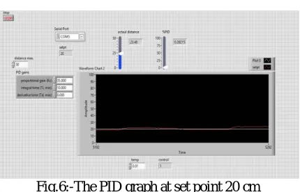
The PID controller is designed and applied on the PWM pin of the DC motor to maintain a threshold distance with the obstacle and vary the PWM according to the obstacle appearing on the path.
Fig.6:-The PID graph at set point 20 cm
The PID parameters obtained here by trail and error method is summarized under the table:-
Table 2:-Tuned PID parameters at set point 20 cm
Kp 35
Ki 10
Kd 0
VII.CONCLUSION
The autonomous guidance vehicle developed here has successfully achieved its major goal of being a low cost and efficient system as it is following a local method for path planning along with successfully avoiding the obstacles on the corridor system developed for the purpose of emergency bed transportation. The colour detection scheme designed successfully matches the intensity of colored floor for automatically start and stop the vehicle once it reaches its destination. The PID algorithm is successfully applied to control the PWM of the motors to control the speed which gets reduced when the obstacle is near and the speed is increased when there is no obstacle in the path along with maintaining the threshold distance with the obstacle.
VIII.FUTURE SCOPE
As the system developed for the purpose of the hospital environment, the obstacle detection scheme developed here consists of the static objects along with the human detection. But there is a need of a more powerful hardware system to correctly deal with human detection and the system must be able to differentiate between the human and static objects Here, for the initial testing a robot vehicle was made to navigate safely through a corridor without bumping into anyone or anything. Here, the robot is always navigating under a known path using the local detection method, which can be overcome implementing a fuzzy navigation algorithm along with the A* algorithm for global path planning so that the robot can be able to navigate easily from one place to another without the need to be trained under the same route.
REFERENCES
[1] Limin Ren , Weidong Wang, “A new fuzzy intelligent obstacle avoidance control strategy for wheeled mobile robot” Conference paper on Mechatronics and Automation (ICMA), 2012.
[2]Chandra Sekhar Pati and Rahul Kala ,” Vision-Based Robot Following Using PID Control” Technologies 2017, 5(2), 34; doi:10.3390/technologies5020034.
[3] Nils Gageik, Thilo Müller, Sergio Montenegro ,” Obstacle Detection And Collision Avoidance Using Ultrasonic Distance Sensors For An Autonomous Quadrocopter”,2012.
[4] Kunal Agarwal , Shadan Mahtab , Sourav Bandyopadhyay, Sauvik Das Gupta,” A Proportional-Integral-Derivative Control Scheme of Mobile Robotic platforms using MATLAB”, IOSR Journal of Electrical and Electronics Engineering (IOSR-JEEE) e-ISSN: 2278-1676,p-ISSN: 2320-3331, Volume 7, Issue 6 (Sep. - Oct. 2013), PP 32-39.
[6] S. Erdis, “Robot-assisted hospital bed transport,'' Master’s Thesis, Rebro University, 2010.
[7] Gyula Mester “Sensor-based navigation of a mobile robot in an indoor environment,” Robotics and Autonomous systems, vol. 38, no. 1, pp. 1— 18,2010.
[8] Rakesh Chandra Kumar1 & Md. Saddam Khan,” Obstacle Avoiding Robot – A Promising One”, International Journal of Advanced Research in Electrical, Electronics and Instrumentation Engineering,Vol. 2, Issue 4, April 2013.
[9] Masaki takahasi & Takafumi Suzuki .”A mobile robot for transport applications in hospital domain with safe human detection algorithm”, Conference on Proceedings of the 2009 international conference on Robotics and biomimetics.