Scholarship@Western
Scholarship@Western
Electronic Thesis and Dissertation Repository
8-9-2018 2:30 PM
Hydrodynamics of a Gas-Driven Gas-Liquid-Solid Spouted Bed
Hydrodynamics of a Gas-Driven Gas-Liquid-Solid Spouted Bed
Jia Meng
The University of Western Ontario Supervisor
Jesse Zhu
The University of Western Ontario Co-Supervisor Dominic Pjontek
The University of Western Ontario
Graduate Program in Chemical and Biochemical Engineering
A thesis submitted in partial fulfillment of the requirements for the degree in Master of Engineering Science
© Jia Meng 2018
Follow this and additional works at: https://ir.lib.uwo.ca/etd
Part of the Complex Fluids Commons, and the Other Chemical Engineering Commons
Recommended Citation Recommended Citation
Meng, Jia, "Hydrodynamics of a Gas-Driven Gas-Liquid-Solid Spouted Bed" (2018). Electronic Thesis and Dissertation Repository. 5518.
https://ir.lib.uwo.ca/etd/5518
This Dissertation/Thesis is brought to you for free and open access by Scholarship@Western. It has been accepted for inclusion in Electronic Thesis and Dissertation Repository by an authorized administrator of
i
A novel cylindrical gas-driven gas-liquid-solid spouted bed was developed in this project, which has a
high potential to be used for a biological wastewater treatment process. Solids motion, flow regimes,
and regime transitions in this system were studied. With increasing gas velocity, four regimes were
identified, including: fixed bed, semi spouted bed, full spouted bed and internal circulating fluidized
bed. The respective gas velocities for the transitions between the four regimes were experimentally
identified and termed as minimum spouting velocity, full spouting velocity and minimum circulating
velocity. A new “basketing” method was adopted to measure the minimum spouting velocity while the
particle velocity and dense phase retraction in the annulus were monitored to determine the full spouting
velocity and minimum circulating velocity. The effects of key operating parameters on the three
transitional velocities were examined in this novel spouted bed. When a draft tube was present, these
three velocities increased with increasing particle density and draft tube length. The minimum spouting
velocity and full spouting velocity were not affected when varying the nozzle-tube gap, while the
minimum circulating velocity increased with longer nozzle-tube gaps. Without a draft tube, the
gas-driven gas-liquid-solid spouted bed stability is reduced, where results were mainly obtained in terms of
the water level, initial static bed height and gas flowrate.
Keywords
ii
Co-Authorship Statement
Title: Hydrodynamics in Gas-driven Gas-liquid-solid Spouted Bed with Draft Tube
Author: Jia Meng, Jesse Zhu, Dominic Pjontek, Xinran Li
The experimental apparatus of gas-driven gas-liquid-solid spouted bed with draft tube was
constructed by Jia Meng under guidance of the advisors. Jia Meng performed all the experiments and
drafted this paper. Xinran Li provided useful assistance in some experiments. Data analyses and process
were undertaken under the advice of Dr. Jesse Zhu and Dr. Dominic Pjontek. The final version of this
paper is ready for submission
Tittle: Hydrodynamics in Gas-driven Gas-liquid-solid Spouted Bed without Draft Tube
Author: Jia Meng, Jesse Zhu, Dominic Pjontek
The experiment apparatus of gas-driven gas-liquid-solid spouted bed without draft tube was
constructed by Jia Meng under guidance of the advisors. Jia Meng performed all the experiments and
draft this paper. Data analysis and modification were undertaken with advice of Dr. Jesse Zhu and Dr.
iii
Acknowledgments
I would like to express my sincerely appreciation to all people who have been supporting me
and helping me in my academic and daily life.
My sincerely gratitude to Dr. Jesse Zhu for being my supervisor. Thanks to his motivation and
supervision especially for giving me this opportunity to pursue my master study. His knowledge and
enthusiasm not only stimulate me throughout the study, but also broaden my horizon for the years to
come.
My heartful thanks to Dr. Dominic Pjontek for being my co-supervisor. His knowledge
provided very good support to my thesis and help me solve my puzzles in this project. Thanks to his
patience in helping me improving my English writing. It has been a pleasure to work with him.
Much appreciation to George Zhang and Tian Nan for their help in equipment construction and
technician support.
Special thanks to Bowen Dreuw for his great help in proof-reading the final draft of my thesis.
Many thanks to my friends and group member for their advice and support.
Great gratitude to my parents for their selfless supports and for continuous encouragement.
Finally, I would like to express my heartful thanks to my girlfriend Tianzi Bai. I cannot insist
iv
Table of Contents
Abstract ... i
Co-Authorship Statement... ii
Acknowledgments... iii
Table of Contents ... iv
List of Tables ... vii
List of Figures ... viii
List of Appendices ... x
Nomenclature ... xi
Chapter 1 ... 1
1
General Introduction ... 1
Background ... 1
Thesis objectives ... 8
Thesis structure ... 9
Reference ... 10
Chapter 2 ... 12
2
Hydrodynamics of a Gas-Driven Gas-Liquid-Solid Spouted Bed with Draft Tube .... 12
Background information ... 12
Experimental apparatus and methods ... 17
2.2.1
Experiment apparatus... 17
2.2.2
Particle properties ... 18
2.2.3
Measurement methods ... 20
General description of gas driven gas-liquid-solid spouted bed ... 23
Regime transition velocities ... 27
v
2.4.2
Full spouting velocity ... 28
2.4.3
Minimum circulating velocity... 29
Effects of operating conditions ... 30
2.5.1
Draft tube length ... 30
2.5.2
Nozzle-tube gap ... 33
2.5.3
Particle density ... 36
Particle accumulation rate measurement ... 38
Summary ... 41
References ... 42
Chapter 3 ... 45
3
Hydrodynamics in Gas-Driven Gas-Liquid-Solid Spouted Bed without a Draft Tube 45
Background information ... 45
Experimental apparatus and methods ... 48
3.2.1
Experimental apparatus ... 48
3.2.2
Particle properties ... 49
3.2.3
Methods... 50
Result and discussion ... 51
3.3.1
Attempt of spouting regime construction ... 51
3.3.2
Effect of gas flowrate on dead zone length ... 52
3.3.3
Effect of initial static bed height on dead zone length ... 53
3.3.4
Effect of water level on dead zone length ... 54
Summary ... 56
Reference ... 57
Chapter 4 ... 59
4
Conclusions and Future Work ... 59
vi
Future Work ... 60
Appendices ... 61
Appendix A. Example of error analysis ... 61
Appendix B. Rotameter calibration... 63
Appendix C. Data of experiments ... 65
vii
List of Tables
Table 2.1 Previous studies for non-conventional spouted bed ... 14
Table 2.2 Experimental particle properties ... 19
Table 2.3 Operating conditions of this work ... 26
Table 2.4 Deviation of calculated and experimental w
p... 40
viii
List of Figures
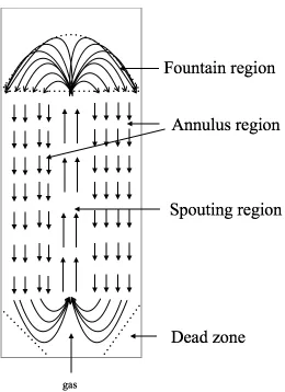
Figure 1.1 Particle motion in spouted bed configurations. Arrows indicate direction of solids
motion. ... 2
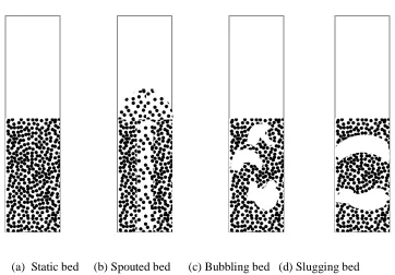
Figure 1.2 Spouted bed flow regimes with increasing gas flow. ... 3
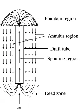
Figure 1.3 Particle motion in spouted bed with a draft tube. Arrows indicate direction of solids
motion. ... 4
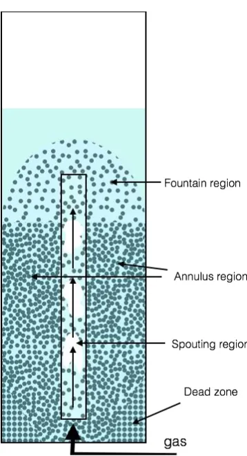
Figure 1.4 Sketch of gas-driven gas-liquid-solid spouted bed with draft tube. Arrows indicate
direction of gas motion. ... 6
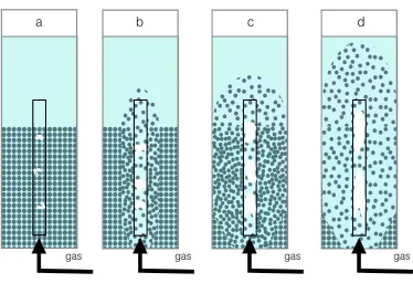
Figure 1.5 Regime transition with increasing superficial gas velocity (a) fixed bed; (b) semi
spouted bed; (c) full spouted bed; (d)internal circulating fluidized bed. ... 7
Figure 1.6 Sketch of the proposed gas-driven gas-liquid-solid spouted bed without draft tube.
Arrows indicate direction of gas flow. ... 8
Figure 2.1 Particle moving track in spouted bed ... 13
Figure 2.2 Four regions in gas-driven gas-liquid-solid spouted bed ... 16
Figure 2.3 Apparatus of gas-driven gas-liquid-solid spouted bed with draft tube... 18
Figure 2.4 Images of particles used in the experiment (unit of ruler is cm) ... 19
Figure 2.5 Typical pressure drop in gas-solid spouted bed ... 21
Figure 2.6 Experimental pressure drop profile in ... 21
Figure 2.7 Schematic of gas-driven gas-liquid-solid spouted bed with draft tube (Arrows
indicate direction of gas motion) ... 23
Figure 2.8 Regime transition with increasing superficial gas velocity (a) fixed bed; (b) semi
spouted bed; (c) full spouted bed; (d)internal circulating fluidized bed ... 25
ix
Figure 2.10 Particle velocity in the annulus versus superficial gas velocity ... 29
Figure 2.11 Dense phase retraction versus superficial gas velocity ... 30
Figure 2.12 Effect of draft tube length on minimum spouting velocity ... 31
Figure 2.13 Effect of draft tube length on full spouting velocity ... 32
Figure 2.14 Effect of draft tube length on minimum circulating velocity ... 33
Figure 2.15 Nozzle-tube gap effect on full spouting velocity ... 34
Figure 2.16 Nozzle-tube gap effect on minimum circulating velocity ... 35
Figure 2.17 Particle density effect on minimum spouting velocity ... 36
Figure 2.18 Particle density effect on full spouting velocity ... 37
Figure 2.19 Particle density effect on minimum circulating velocity ... 38
Figure 2.20 Comparison of experimental particle accumulation and calculated particle
accumulation in basket ... 40
Figure 3.1 Schematic diagram of a spouted bed. Arrows indicate direction of solids motion.
... 46
Figure 3.2 Flow regime transition with increasing gas flow ... 47
Figure 3.3 Apparatus of gas-driven gas-liquid-solid spouted bed without draft tube ... 49
Figure 3.4 Particle motion and dead zone at wall above the nozzle exit level ... 51
Figure 3.5 Dead zone length variance with gas flowrate (ABS particle) ... 53
Figure 3.6 Dead zone length variance with initial static bed height (ABS particle) ... 54
x
List of Appendices
Appendix A. Example of error analysis ... 61
Appendix B. Rotameter calibration ... 63
xi
Nomenclature
Ar Archimedes number
CD Drag coefficient
Db Diameter of basket (mm)
Di Inner diameter of Column (mm)
Dt Inner diameter of draft tube (mm)
dn Inner diameter of nozzle (mm)
g Gravitational acceleration (m/s2)
He Nozzle-tube gap (mm)
Hde Dense phase height in annulus region (mm)
Hde0 Initial dense phase height (mm)
Hs Initial static bed height (mm)
Hw Water level higher than initial static bed height (mm)
Ld Draft tube length (mm)
Ln Non-mobile zone length at column wall (mm)
mp Particle mass in basket (g)
△h Vertical distance (mm)
xii
△t Time variation (s)
Qg Gas flowrate (l/min)
Re Reynolds number
ug Superficial gas velocity (mm/s)
umfs Full spouting velocity (mm/s)
ums Minimum spouting velocity (mm/s)
up Particle velocity in annulus (mm/s)
ut Terminal velocity (mm/s)
wp particle mass accumulation rate (g/s)
wpb Particle mass accumulation rate in the basket (g/s)
ρ Density of fluid (kg/m3)
ρp Density of particle (kg/m3)
ρb Bulk density of particle (kg/m3)
ρw Density of water (kg/m3)
Chapter 1
1
General Introduction
Background
A conventional gas-solid spouted bed contains a vessel filled with coarse particles and fluid
injected vertically at the center of the column bottom. The fluid injection results in an upwards
movement of particles at the center of the column until they break through the static bed and fall
back into the annulus region due to gravity. This is the basic particle flow regime of a spouted bed
(Epstein & Grace, 2011). Once the spouted bed flow regime is stable, this system can be divided
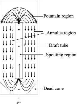
into four regions, as shown in Figure 1.1, which includes the spouting region, fountain region,
annulus region and dead zone. The spouting region is usually at the center of the column above the
fluid inlet nozzle where the particles rise quickly with relatively lower concentration and directly
influenced by the fluid flow. The region surrounding the spout region is referred as the annulus
region, where particles fall downwards slowly at much higher concentrations. The fountain region
is located above the bed surface, where particles reach their highest position and then fall back to
the annulus region. The previous zones provide the general description of the solids circulation
pattern. At the base of the column, there is a region where the particles remain non-mobile,
Figure 1.1 Particle motion in spouted bed configurations. Arrows indicate direction
of solids motion.
Figure 1.2 illustrates the regime transitions of gas-solid spouted beds when increasing the
gas superficial velocity (Epstein & Grace, 2011). The fixed packed bed may however directly
change from packed bed into a bubbling bed, as a stable spouted bed may not be developed when
the initial static bed height is higher than the maximum spoutable height of this system (Epstein &
Grace, 2011). This is because the gas leaks from spouting region to annulus region, breaking the
spouting regime when the static bed height is higher than the maximum spoutable height (Mathur
& Epstein, 1974). The leaking gas fluidizes the particles in the annulus region and prevents them
and eliminate the static bed height limitation. In addition, the draft tube can prevent solids cross
flow between spouting region and annulus region (Neto et al., 2008), as illustrated in Figure 1.3.
(a) Static bed (b) Spouted bed (c) Bubbling bed (d) Slugging bed
Figure 1.3 Particle motion in spouted bed with a draft tube. Arrows indicate
direction of solids motion.
The gas-solid spouted bed was first invented by Mathur and Gisher in the 1950’s (Mathur
& Gisher, 1955) as an efficient high heat transfer equipment to dry wheat. It then gradually began
to see use in many other industry processes, such as gasification (Jarungthammachote & Dutta,
2008), catalytic polymerizations (Olazar et al., 1994), biomass pyrolysis (Amutio et al., 2011) and
tablets coating (Kucharski & Kmiec, 1983).
Novel spouted beds were periodically proposed, including a liquid-solid spouted bed
(Grbavcic et al., 1992) and a liquid-driven gas-liquid-solid spouted bed (Wang et al. 2003). These
systems require liquid net flow to form stable spouting phenomenon. However, research has not
spouting. Therefore, a new system is proposed that utilizes gas only to form a spouted bed.
Gas-liquid-solid spouted bed has a high potential to be used in wastewater treatment processes when
the liquid net flowrate through the system is limited, such as the aeration process unit. In this
application, the gas-driven system stands out as the energy input required to spout particles can be
provided by the aeration gas so that there is no need to recirculate the liquid to form spouting.
Therefore, the energy consumption for liquid net flow is saved.
This work therefore proposes a gas-liquid-solid spouted bed driven by gas flow only to
form a stable spouted regime and the development of the required measurements methods for
regime transition. Figure 1.4 shows a typical sketch of a gas-driven gas-liquid-solid spouted bed
with draft tube. Particles are loaded in the cylindrical column. A nozzle at the center of the column
base injects gas vertically into the system. There is no liquid net flow as the gas is the only driven
factor in this system.
A gas-driven gas-liquid-solid spouted bed can be described based on the same four regions
as the gas-solid spouted bed. However, the resulting flow regimes when increasing the gas flow
rate, as shown in Figure 1.5, differ from the gas-solid configuration. Particle circulation is first
developed near the outside of the draft tube and then expands to the entire annulus region. The flow
regime finally changes to internal circulating fluidized bed at higher superficial gas velocities. The
superficial gas velocity which spouts and circulates the particles near the outside of the draft tube
is called the minimum spouting velocity (ums), while the velocity which spouts the whole system is
called the full spouting velocity (umfs). For these flow regimes, the particles in the annulus region
move downward and come in contact with each other. The particles thus form a dense phase in the
annulus and a dilute phase in fountain, as shown in Figure 1.5 (b) and (c). Above a certain
superficial gas velocity, referred as the minimum circulating velocity, the dense phase is eliminated.
The spouted bed is then operating as an internal circulating fluidized bed where all the particles are
Figure 1.4 Sketch of gas-driven gas-liquid-solid spouted bed with draft tube. Arrows
Figure 1.5 Regime transition with increasing superficial gas velocity (a) fixed bed;
(b) semi spouted bed; (c) full spouted bed; (d)internal circulating fluidized bed.
A gas-driven gas-liquid-solid spouted bed without a draft tube is also studied in this work,
as shown in Figure 1.6. The nozzle at the center introduces a vertical gas jet in this system to form
a spout. Again, there is no liquid net flow in this system. Similar to the gas driven system with a
draft tube, it has four regions to describe the particle flow. The dead zone length at wall (Ln) is
studied to better understand the design of future conical bottoms to avoid creation of a dead zone
Figure 1.6 Sketch of the proposed gas-driven gas-liquid-solid spouted bed without
draft tube. Arrows indicate direction of gas flow.
Thesis objectives
The main objective of this thesis is to develop and characterize a novel gas-driven gas-liquid-solid
spouted bed and to gain a basic understanding of its overall hydrodynamics. The specific objectives
1. Design and construct a gas-driven gas-liquid-solid spouted bed.
2. Develop suitable measurement methods for relevant hydrodynamic characteristics in the
gas-driven gas-liquid-solid spouted bed with draft tube, including minimum spouting velocity (ums),
full spouting velocity (umfs) and minimum circulating velocity (uci).
3. Investigate the impacts of draft tube length (Ld), nozzle-tube gap (He) and particle density (ρp)
on the minimum spouting velocity (ums), full spouting velocity (umfs) and minimum circulating
velocity (uci).
4. Investigate the impact of static bed height (Hs), water level (Hw), and gas flowrate (Qg) on the
dead zone length at wall (Ln) in the gas-driven gas-liquid-solid spouted bed without a draft tube.
Thesis structure
This thesis contains four chapters:
Chapter 1 provides a general introduction, the thesis objectives, and the thesis structure.
Chapter 2 investigates the gas-driven gas-liquid-solid spouted bed with a draft tube. The dffects of
draft tube length, nozzle-tube gap and particle density on regime transition velocities including
minimum spouting velocity, full spouting velocity, minimum circulating velocity. Comparison of
two methods to measure particle accumulation rate is also provided.
Chapter 3 investigates the gas-driven gas-liquid-solid spouted bed without a draft tube. The effects
of water level, initial static bed height and gas flowrate on the dead zone length at wall are studied.
Reference
Amutio, M., Lopez, G., Artetxe, M., Elordi, G., Olazar, M., & Bilbao, J. (2011). Influence of
temperature on biomass pyrolysis in a conical spouted bed reactor. Resources, Conservation and
Recycling. 59, 23-31
Epstein, N., & Grace, J.R. (2011). Introduction. Chapter 1 of Spouted and Spout-Fluid Beds edited
by Epstein, N. & Grace,J. Cambrige, UK
Gokon, N., Takahashi, S., Yamamoto, H., & Kodama, T. (2008). Thermochemical two-step
water-splitting reactor with internally circulating fluidized bed for thermal reduction of ferrite particles.
International Journal of Hydrogen Energy. 33, 2189-2199
Grbavcic, Z., Vukovic, D., Jovanovic, S., Garic, R., Hadzismajlovic, D., Littman, H., & Morgan,
M. (1992). Fluid flow regime and solids circulation rate in a liquid phase spout-fluid bed with draft
tube. The Canadian Journal of Chemical Engineering. 70, 895-904
Jarungthammachote, S. & Dutta, A. (2008). Equilibrium modeling of gasification: Gibbs free
energy minimization approach and its application to spouted bed and spout-fluid bed gasifiers.
Energy Conversion and Management. 49, 1345-1356
Jose, M., Olazar, M., Llamosas, R., Izquierdo, M., & Bilbao,J. (1996). Study of dead zone
and spout diameter in shallow spouted beds of cylindrical geometry.
The Chemical
Engineering Journal
.
64
, 353-359
Kucharski, J., & Kmiec, A. (1983). Hydrodynamics, heat and mass transfer during coating of tablets
in a spouted bed. The Canadian Journal of Chemical Engineering. 61, 435-439.
Mathur, K.B., & Gisher, P. (1955). A study of the application of the spouted bed technique to wheat
drying. Journal of Applied Chemistry. 5, 624-636
Neto, V., Duarte, C., Murata, V., & Barrozo, M. (2008). Effect of a draft tube on a fluid dynamics
of a spouted bed: experimental and CFD studies. Drying Technology. 26, 299-307
Olazar, M., Jose, M., Zabala, G. & Bilbao, J. (1994). New reactor in jet spouted bed regime for
catalytic polymerizations. Chemical Engineering Science. 49, 4579-4588
Wang, J., Wang, T., Liu, L., & Chen, H. (2003). Hydrodynamics behavior of a three-phase spouted
Chapter 2
2
Hydrodynamics of a Gas-Driven Gas-Liquid-Solid
Spouted Bed with Draft Tube
Background information
Gas-solid spouted beds were invented in 1955 and initially used as a fluidized bed
configuration designed to dry wheat in Canada (Mathur & Gisher, 1955). The configuration was
gradually used used in other chemical engineering processes, including solids blending, gas
cleaning and thermal cracking (Markowski & Kaminski, 1983). A conventional gas-solid spouted
bed generally consists of a vertical cylindrical vessel filled with particles where gas is injected from
a nozzle at the bottom of the column. The injected gas provides the necessary drag force on the
particles (Epstein & Grace, 2011) to result in an upward flow of the particles at the center of the
column until break through the static bed and fall back into the annulus region due to gravity.
The typical solids circulation pattern for a gas-solid spouted bed, shown in Figure 2.1
(Epstein & Grace, 2011), consists of four regions including the spouting region, annulus region,
fountain region and dead zone. Particles move upward with high velocity and low concentration in
the spouting region, which is driven by the drag force and buoyancy force of the fluid flow (Epstein
& Grave, 2011). The particles then reach the fountain region where they move to the surrounding
and transitions from a rising to a falling state. Next, the particles travel downward with low velocity
and high concentration due to gravity. Finally, the falling particles move from the annulus region
to the spouting region, repeating the same cycle. This concludes the circulating process of particles
in spouted bed. At the bottom of a flat bottom spouted bed, particles close to the bottom walls of
the bed cannot be removed by both gravity and fluid flow, forming a dead zone. The spouting
regime can be broken by increasing gas velocity and form a bubbling and slugging regime (Epstein
Figure 2.1 Particle moving track in spouted bed
(Arrows indicate direction of solids motion)
To expand the application of spouted beds, non-conventional spouted bed configurations
were proposed to address the needs of specific processes including liquid-solid spouted beds
(Grbavcic et al., 1992) and liquid-driven gas-liquid-solid spouted beds (Wang et al. 2003). Table
2.1 shows the prior work of some researchers about the liquid-solid and liquid-driven
gas-liquid-solid spouted bed (Grbavcic et al. 1992; Littman et al.,1974; Anabtawi et al. 2003; Vukovic et al.
1974; Wang et al., 2003; Erbil, 2005), which focus on liquid-solid and liquid-driven
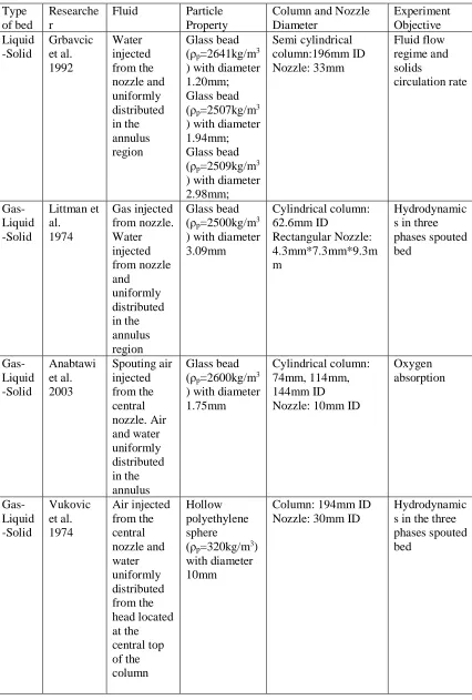
Table 2.1 Previous studies for non-conventional spouted bed
Type of bed
Researche r
Fluid Particle
Property
Column and Nozzle Diameter Experiment Objective Liquid -Solid Grbavcic et al. 1992 Water injected from the nozzle and uniformly distributed in the annulus region Glass bead (ρp=2641kg/m3 ) with diameter 1.20mm; Glass bead (ρp=2507kg/m3 ) with diameter 1.94mm; Glass bead (ρp=2509kg/m3 ) with diameter 2.98mm; Semi cylindrical column:196mm ID Nozzle: 33mm Fluid flow regime and solids circulation rate Gas-Liquid -Solid Littman et al. 1974 Gas injected from nozzle. Water injected from nozzle and uniformly distributed in the annulus region Glass bead (ρp=2500kg/m3 ) with diameter 3.09mm Cylindrical column: 62.6mm ID Rectangular Nozzle: 4.3mm*7.3mm*9.3m m Hydrodynamic s in three phases spouted bed Gas-Liquid -Solid Anabtawi et al. 2003 Spouting air injected from the central nozzle. Air and water uniformly distributed in the annulus Glass bead (ρp=2600kg/m3 ) with diameter 1.75mm
Cylindrical column: 74mm, 114mm, 144mm ID Nozzle: 10mm ID
Oxygen absorption Gas-Liquid -Solid Vukovic et al. 1974 Air injected from the central nozzle and water uniformly distributed from the head located at the central top of the column Hollow polyethylene sphere
(ρp=320kg/m3) with diameter 10mm
Column: 194mm ID Nozzle: 30mm ID
Gas-Liquid -Solid Wang et al. 2003 Water injected from the nozzle and air introduced from a ring type distributor
Glass bead (ρp=2200kg/m3 ) with diameter 10.5mm, 12.0mm, 16.0mm
Column: 230mm ID Nozzle: 16mm ID
Influence of superficial gas velocity, liquid circulation velocity, minimum liquid spouting velocity, pressure drop Gas-Liquid -Solid Erbil 2005 Pulse injected into the spout region. Water pulse introduced into the annulus region. Additionally , air uniformly introduced into annulus region. Glass bead (ρp=2533kg/m3 ) with diameter 3mm
Semi-cylindrical column: 80mm ID Nozzle: 10mm ID
Effect of annulus leakage on particle circulation
The previous studies on non-conventional spouted beds included liquid-driven or
gas-liquid driven systems. Liquid net flow is necessary to spout the particles. However, research has
not been done about the gas-driven gas-liquid-solid spouted bed, which uses only gas flow to form
spouting. Therefore, a new system is proposed that utilizes gas only to form a spouted bed.
Gas-liquid-solid spouted bed has a high potential to be used in wastewater treatment processes when
the liquid net flowrate through the system is limited, such as the aeration process unit. In this
application, the gas-driven system stands out as the energy input required to spout particles can be
provided by the aeration gas so that there is no need to recirculate the liquid to form spouting.
Therefore, the energy consumption for liquid net flow is saved.
To maintain good stability in a proposed gas-driven gas-liquid-solid spouted bed , gas is
water. The gas injection results in an upward movement of the particles at the center of the column
until they break through the static bed and fall back into the annulus region due to gravity. The
spouting for a gas-driven gas-liquid-solid spouted bed share similarity with the gas-solid system
including the four regions phenomenon and particle circulation behavior. Additionally, a draft tube
may be added into this system to avoid gas leakage and particle crossing from the spouting region
to the annulus region as shown in Figure 2.2. The goal of this work is to form the spouting
phenomenon by gas flow only and study hydrodynamics in this system including regimes and
regime transition velocities.
Experimental apparatus and methods
2.2.1
Experiment apparatus
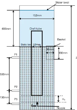
Figure 2.3 presents a schematic of the gas-driven gas-liquid-solid spouted bed used in this
work. Water and air are used as the liquid and gas phases, respectively. The vertical column is made
of transparent plexiglass with 152 mm (6 inch) inner diameter (Di) and 6 mm thickness is open to
the atmosphere. A draft tube with 52 mm inner diameter (Dt) and 4 mm thickness sits at the center
of the column, while the length is varied to investigate the effect of the draft tube length (Ld) on the
hydrodynamics in this system. Three pressure ports located at the column wall are used to measure
the pressure drop in the annulus region. The gas injection nozzle at the center and bottom of the
column has an inner diameter (dn) of 4.5 mm and 1 mm thickness. The water level is maintained at
600mm higher than the initial static bed height. A basket with 36 mm inner diameter, 4 mm
thickness and 130 mm height is placed in the annulus region, with its open-top slightly above the
initial static bed and allowing the measurement of the particle accumulation rate. The nozzle-tube
gap (He) and the draft tube length (Ld) are varied to find their effects on the studied hydrodynamics.
The superficial gas velocity reported in this work is the volumetric gas flowrate divided by the
Figure 2.3 Apparatus of gas-driven gas-liquid-solid spouted bed with draft tube
2.2.2
Particle properties
Three types of particles were investigated in this study including Acrylonitrile Butadiene
Styrene (ABS) particles and two types of plastic particles. Figure 2.4 provides a visual comparison
of the particles and Table 2.2 provides the particle properties. The ABS particle size distribution is
Figure 2.4 Images of particles used in the experiment (unit of ruler is cm)
Table 2
.
2 Experimental particle properties
Archimedes number and terminal velocities were calculated using the following
equations (Khan & Richardson, 1988):
𝐴𝑟 =
34
𝐶
𝐷𝑡𝑅𝑒
𝑡 2= 𝑑
𝑝3
𝜌(𝜌
𝑠− 𝜌)𝑔/𝜇
2(2.1)
𝑅𝑒
𝑡= (2.33𝐴𝑟
0.018− 1.53𝐴𝑟
−0.016)
13.3(2.2)
ParticleType
Particle Density (kg/m3)
Bulk Density (kg/m3)
Particle size (mm)
Volume Equivalent Diameter (mm)
Archimedes Number (-) Terminal Velocity in Liquid (m/s)
ABS
particle 1044 644 2.5 2.5 6738 0.036
Plastic
particle 1 1348 803 0.6-0.8 0.7 1170 0.011
Plastic
𝑢
𝑡=
𝜇𝑅𝑒𝑡𝑑𝑝𝜌𝑝
(2.3)
2.2.3
Measurement methods
In a gas-solid spouted bed, the minimum spouting velocity (ums) is defined as the gas
velocity corresponding to the point at which stable external spouting collapses with decreasing gas
flowrate (Epstein & Grace, 2011). It is generally determined by measuring the pressure drop (△p)
across the bed height as a function of superficial gas velocity in a traditional spouted bed. For a
typical measurement, the pressure drop increases from 0 until reaching a peak value, and then
decreases to a constant value. The minimum spouting velocity is the superficial gas velocity when
the pressure drop becomes constant, as shown in Figure 2.5 (Mathur & Epstein, 1974).
The pressure drop method, however, cannot be used to identify the minimum spouting
velocity for the gas-drive gas-liquid-solid spouted bed. For the gas-driven system, the pressure drop
decreases continuously when increasing the superficial gas velocity, as shown in Figure 2.6. This
measurement difference is mainly because the particle density used in this work is very close to
water, the continuous phase in this system. The pressure drop variance caused by particles cannot
be readily distinguished by the pressure drop method, as shown in Equation 2.4. Furthermore, the
water motion also affects the pressure drop across the bed, making it more difficult to use pressure
drop method to find minimum spouting velocity.
Figure 2.5 Typical pressure drop in gas-solid spouted bed
Figure 2.6 Experimental pressure drop profile in
gas-driven gas-liquid-solid spouted bed
The minimum spouting velocity was thus determined by measuring the particle
accumulation rate (wp) in the gas-driven gas-liquid-solid spouted bed. The particle accumulation
diameter and 4 mm thickness. It has a lid on the top and mesh at bottom. In the measurement, the
basket was placed in the annulus region and the top of the basket is maintained just above as the
static bed height. Once the system forms a stable solid circulating pattern, the lid of basket is
opened, allowing the particles to enter the basket. The basket is then covered again and taken out,
allowing the particles within it to be dried. Finally, the particles are weighed by a balance and the
particle accumulation rate is calculated by Equation 2.5.
𝑤
𝑝=
𝑚△𝑡𝑝 (2.5)where △t=50s
The full spouting velocity is determined by measuring the particle velocity in the annulus
via video analysis. The particles in annulus move downward as packed bed. A 20 second video is
taken between 20 cm to 40 cm from bottom level range of the column. Three particles are selected
randomly to estimate the particle velocity, calculated based on the distance travelled (△h) over a
selected time interval, as shown in Equation 2.6. This process is finished by a video processing
software Shotcut. In this measurement, the wall effect is neglected.
𝑢
𝑝=
△ℎ△𝑡 (2.6)where △t=20s.
The minimum circulating velocity is determined based on the dense phase retraction
(Hde/Hde0) in the annulus region. Dense phase height in the annulus can be directly obtained through
visual observation. The dense phase retraction is calculated by the dense phase height (Hde) over
the initial dense phase height (Hde0). The observation method is feasible because this is a qualitive
General description of gas driven gas-liquid-solid
spouted bed
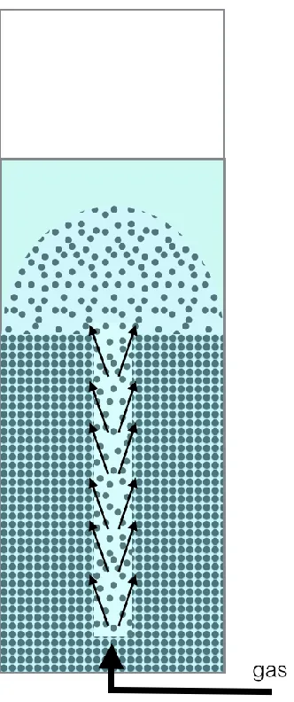
Figure 2.7 illustrates the studied gas-driven gas-liquid-solid spouted bed with a draft tube.
There is a nozzle at the central bottom of the column for gas inlet into this system. There is no net
flow of liquid in and out of the spouted bed and the gas is the only driven factor in this system.
Particles are loaded in the annulus region of the cylindrical column. The gas injection forms bubbles
and results in an upward movement of particles in the draft tube located at the center of the column
until the particles break through the static bed. The particles then fall downward as packed bed in
the surrounding region due to gravity and the particles entrain into the draft tube at the bottom. The
solid circulating motion is similar to gas-solid spouted beds.
Figure 2.7 Schematic of gas-driven gas-liquid-solid spouted bed with draft tube
The gas-driven gas-liquid-solid spouted bed can be divided into four regions, including
spouting region, annulus region, fountain region and dead zone, similar to gas-solid spouted beds.
It has four flow regimes including fixed bed, semi spouted bed, full spouted bed and internal
circulating fluidized bed. When gas velocity is low, gas is injected into the column at a flow rate
that is not high enough to spout the particles. Particles remain stationary, resulting in a fixed bed
regime, as shown in Figure 2.8 (a). As gas flow is increased, more bubbles with higher rising
velocities flow through the draft tube, and the particles begin circulating between the spouting
region and the partial annulus, transitioning into a semi spouted bed, as illustrated in Figure 2.8 (b).
As the gas velocity further increases, more particles in the spouting region are spouted upward and
more particles in the annulus region begin moving downwards to compensate. The particles close
to column wall are fully in motion which is referred as the full spouted bed and is illustrated in
Figure 2.8 (c). Finally, further increasing the gas velocity spouts the particles higher and forms a
much larger fountain region. The particles in the annulus region decrease to a point where the dense
phase height cannot be observed. The particles in annulus region change from moving downward
as packed bed to free falling. thus becoming an internal circulating fluidized bed (Gokon et al, 2008)
as shown in Figure 2.8 (d).
The superficial gas velocity which can spout the particles and result in partial solids
circulation in the annulus is called minimum spouting velocity (ums). Gas flow breaks the
loose-packed bed in the draft tube. The particles in the spouting region move upwards with high velocity
and low concentration. The particles in the annulus close to the draft tube begin moving downward
with high concentration and low velocity. Under this gas velocity, the regime changes from the
fixed bed to the semi spouted bed, as shown in Figure 2.8 (a) to Figure 2.8 (b). The superficial
velocity which can spout the whole system is called full spouting velocity (umfs). More particles in
region move upwards with higher velocity. Therefore, the particles close to the wall begin moving.
Under this gas velocity, the regime changes from semi spouted bed to full spouted bed, as shown
in Figure 2.8 (b) to Figure 2.8 (c). The superficial gas velocity which can change the particles in
the annulus moving downward as packed bed to free falling is called minimum circulating velocity
(uci). Less particles exist in the annulus region as it changes to the dilute phase because the particles
in the spouting region move with much higher velocity as well as spouting much higher and forming
a bigger fountain, resulting in more particles located in the upper area of the spouted bed. Under
this gas velocity, the regime changes from full spouted bed to internal circulating fluidized bed as
displayed in Figure 2.8 (c) to Figure 2.8 (d).
Figure 2.8 Regime transition with increasing superficial gas velocity (a) fixed bed;
(b) semi spouted bed; (c) full spouted bed; (d)internal circulating fluidized bed
Three velocities are studied in this project including minimum spouting velocity (ums), full
gas-driven gas-liquid-solid spouted bed provide important hydrodynamic characteristics for this
configuration. In the previous research of spouted bed, it has been found that the particle properties
and the bed geometry of structures affect the hydrodynamics in spouted bed, including draft tube
length (Grbavicic et al., 1992), nozzle-tube gap (Zhao et al., 2006) and particle density (Mathur &
Gisher, 1955). The density difference between liquid and solid can affect the hydrodynamics in this
system. Therefore, this project used three kinds of particles with different densities to find the
density effect on the regime transition process. ABS particle with different draft tube lengths,
nozzle-tube gaps were used to find the effects of geometry factors on the regime transition process.
The operating conditions used in this study are summarized in Table 2.3.
Table 2.3 Operating conditions of this work
ABS particles
Plastic particles 1 and
2
Draft tube length, L
d(mm)
300
600
900
900
Initial static bed height, H
s(mm)
300
600
800 900
800
Nozzle-tube gap, H
e(mm)
0
0 20 40
0
0
Superficial gas velocity, u
g(mm/s)
Regime transition velocities
2.4.1
Minimum spouting velocity
The minimum spouting velocity is the regime transition velocity from fixed bed to semi
spouted bed. It is measured by the basket method. The particle accumulation rate can be measured
by the collection of particles in the basket located adjacent to the draft tube and the top of the basket
is slightly above the top of the initial static bed.
With increasing superficial gas velocity, the particle accumulation rate (wp) increases, as
shown in Figure 2.9. A sharp increase is observed because particle circulation starts when the gas
velocity is higher than the minimum spouting velocity. The particle accumulation rate above the
minimum spouting velocity (ums) increases proportionally with superficial gas velocity. This is due
to the higher superficial gas velocity spouting more particles in the draft tube as drag force is higher
and causing a higher solid circulation rate. There will be a cross point M on the horizontal line and
the regression line of this series of measurements. Point M is defined as the minimum spouting
velocity. The particle accumulation rate at lower superficial gas velocity is not zero due to the
existing particle density distribution. Some particles with lower density can be spouted up at very
Figure 2.9 Particle accumulation rate versus superficial gas velocity
2.4.2
Full spouting velocity
The full spouting velocity (umfs) is defined as the superficial velocity when the regime
changes from semi spouted bed to full spouted bed. It is determined based on the particle
downwards velocity in the annulus at wall (up).
With increasing gas velocity, so increases the particle velocity in the annulus, as shown in
Figure 2.10. There is a sharp increase because the particles close to the column wall begin moving
when the superficial gas velocity is higher than full spouting velocity. At this point, all particles
begin moving, except those in the dead zone. The particle velocity in the annulus increases
proportionally with superficial gas velocity in the full spouting regime. This is also due to the higher
gas velocities spouting more particles in the spouting region. Particles in the annulus region need
to compensate for the void created by the higher gas velocity spouting more particles. Therefore,
of liquid motion is neglected because the particles move downwards as packed bed. There is a cross
point N of the horizontal line and the regression line, which is defined as the full spouting velocity.
Figure 2.10 Particle velocity in the annulus versus superficial gas velocity
2.4.3
Minimum circulating velocity
The minimum circulating velocity (uci) is defined as the superficial velocity when the
regime changes from full spouted bed to internal circulating fluidized bed. It is determined based
on the dense phase retraction method.
With increasing superficial gas velocity, the dense phase retraction is faster, as shown in
Figure 2.11. There is a sudden change of dense phase height to zero. This is because the particles
in the annulus region to flow to the draft tube is faster than the particle in the fountain to flow to
the annulus. Therefore, the dense phase height can no longer be visually determined. The system
thus changes to an internal circulating regime. The superficial gas velocity corresponding to this
increasing the superficial gas velocity. This is because the higher gas velocity forms a bigger
fountain region. More particles located in the fountain results in fewer particles in the annulus dense
phase region.
Figure 2.11 Dense phase retraction versus superficial gas velocity
Effects of operating conditions
2.5.1
Draft tube length
The minimum spouting velocity increases with increasing draft tube length, as shown in
Figure 2.12. This phenomenon may be due to the increased solids in the longer draft tube, requiring
higher superficial gas velocities to spout. The more particles thus require more fluid flow to break
the loose-packed bed. This result agrees with the previous observations in a gas-solid spouted bed
(Mathur & Gisher, 1955). In addition, the slopes of these three lines are approximately equal,
indicating that the comparable particle accumulation rate increases as a function of superfical gas
gas velocity can provide the same increasing of drag force to spout the same weight of particles.
The same partial of these particles finally accumulate in the basket. The particle accumulation
increasings have the same rate in different groups.
Figure 2.12 Effect of draft tube length on minimum spouting velocity
The full spouting velocity increases with increasing draft tube length, as shown in Figure
2.13. This is because the increasing amount of solid in longer draft tube requires higher superficial
gas velocity to break through the loose-packed bed, as explained in Figure 2.12. In addition, a
longer draft tube has more particles in the annulus region adjacent to the draft tube. Therefore, the
circulation development become slower from center to surrounding and the particles close to the
wall require higher superficial gas velocity to move. In addition, the slopes of these two lines are
approximately the same, implying that the particle velocity in the annulus region increases
the same increasing of superficial gas velocity can spout the same weight of particles, as explained
in Figure 2.12. The equivalent weight of particles are required to compensate the spouting region
from the annulus region, resulting in the same increased particle moving velocity in the annulus
region.
Figure 2.13 Effect of draft tube length on full spouting velocity
The minimum circulating velocity increases with increasing draft tube length, as shown in
Figure 2.14. Although the retraction for tube 90cm does not change to zero, it is evident that it
has a higher minimum circulating velocity, as illustrated in Figure 2.14. This result was expected
as both the minimum spouting velocity and full spouting velocity for a longer draft tube were
higher, as explained in Figure 2.12 and Figure 2.13. In addition, increased solids in the annulus
region with longer draft tube has a higher dense phase to retract, requiring a higher superficial gas
velocity. Therefore, a longer draft tube group requires a higher gas velocity to form a internal
Figure 2.14 Effect of draft tube length on minimum circulating velocity
2.5.2
Nozzle-tube gap
The nozzle-tube gap is the distance between the bottom of the draft tube and top of the gas
nozzle. It has been proven that the particle velocity in the annulus region increases with larger
nozzle-tube gap in gas-solid systems (Zhao et al. 2006). Therefore, the impact of the nozzle-tube
gap is studied in this work for the gas-driven gas-liquid-solid spouted bed.
The full spouting velocities for different nozzle-tube gaps are approximately the same, as
shown in Figure 2.15. This is because equal amounts of solids require the same superficial gas
velocity to break the loose-packed bed and the solids in the annulus can compensate for the spouting
region. In addition, theslopes of these three lines vary, indicating that higher nozzle-tube gap group
leads to higher particle velocity in the annulus. This phenomenon may be due to some gas leaks
into the annulus region. The leaking gas occupies space in the annulus as the buoyancy force of
allowing the particles to settle more quickly. In addition, a higher nozzle-tube gap provides more
space for particles to cross from the annulus to the spouting region, increasing the particle velocity.
This phenomenon has also been observed in a gas-solid system (Berruti et al., 1988; Zhao et al.,
2006).
The minimum circulating velocity increases with decreasing nozzle-tube gap, as shown in
Figure 2.16. This may be because the leaking gas in the annulus region and more space for higher
gap cause the particles in the annulus region moving more quickly, as shown in Figure 2.15.
Therefore, the quantity of particles in the annulus region decreases more rapidly for a longer
nozzle-tube gap as it requires less superficial gas velocity increasing to change to a internal circulating
bed.
2.5.3
Particle density
The minimum spouting velocity increases with increasing particle density, as shown in
Figure 2.17. This phenomenon is due to the particles with higher density being more difficult to
spout as they are heavier, requiring a higher superficial gas velocity to provide the necessary drag
force to break the loose-packed bed.
Figure 2.17 Particle density effect on minimum spouting velocity
The full spouting velocity increases with increasing particle density, as shown in Figure
2.18. This is because the particle with higher density is harder to spout as explained in Figure 2.17.
The particles require a higher superficial gas velocity to begin circulation. Additionally, the
fountain is smaller for a particle with higher density, resulting in the particles located in fountain
annulus to the column wall is thus slower. The semi circulation solids flow pattern can be better
maintained so that the particles close to wall are more difficult to move.
Figure 2.18 Particle density effect on full spouting velocity
The minimum circulating velocity increases with particle density, as shown in Figure 2.19.
It is evident that the particle with higher density have slower dense phase retraction, indicating the
particles with higher density has a higher minimum circulating velocity. This is because both the
minimum spouting velocity and full spouting velocity are higher for a particle with higher density,
as explained in Figure 2.17 and Figure 2.18. The particles are harder to spout and settle more easily.
Figure 2.19 Particle density effect on minimum circulating velocity
Particle accumulation rate measurement
Two methods were used to estimate particle accumulation rate in this work, the basket
method and an estimate based on the particle velocity in the annulus region. The basket can directly
measure how weight particles accumulates in the annulus, while the estimate from the particle
velocity is based on measurements at the wall of the column. The particle and particle velocity
distribution are assumed to be uniform in the radial and vertical directions when the spouted bed
achieves full spouting regime. In addition, the voidage in dense phase in the spouting regime is
assumed to be the same as the packed bed. The particle accumulation rate can thus be calculated in
the basket (wpb) using Equation 2.7:
𝑤
𝑝𝑏= 𝑢
𝑝×
𝜋4× (𝐷
𝑖2− 𝐷
𝑡2) × 𝜌
𝑏×
𝜋 4×𝐷𝑏2 𝜋4×(𝐷𝑖2−𝐷𝑡2) (2.7)
𝑤
𝑝𝑏=
𝜋𝑢𝑝𝜌𝑏𝐷𝑏 24 (2.8)
In Equation 2.7 and 2.8, wpb is the particle mass accumulation rate in the basket, up is the
particle moving velocity in annulus, ρb is the particle density, Db is the inner diameter of basket.
The set of data for the plastic particles 2 were selected to study the particle accumulation
rate (wp) comparison between the basket method and the calculation from the particle velocity in
the annulus region at wall, as shown in Figure 2.20. The calculated values are lower in the low
superficial gas velocity region. This may be because the particle velocity in the central annulus
region is higher than that at wall (Schlichting & Gersten, 2017; He et al.,1994), causing the
calculation value to be smaller than the actual value. In the high superficial gas velocity region, the
calculation rate is larger than the basket method. This may be because the dense phase in the
annulus region becomes looser when the superficial gas velocity is high (He et al., 1994; Pianarosa
et al., 2000), meaning the bulk density is higher than the dense phase density in the annulus region.
Therefore, the calculation value is higher than the actual value. The minimum spouting velocity
under this operating condition is 11 mm/s as shown in Figure 2.20. The deviation between the
calculation particle accumulation rate in the basket and experimental particle accumulation rate in
the basket is smaller than 10% as shown in Table 2.4, which shows that the particle circulation rate
can be roughly calculated by the particle downward velocity in the superficial gas velocity range
Table 2.4 Deviation of calculated and experimental w
pSuperficial gas velocity (mm/s) 15 16 17 18 19 20 21 22
Calculated wp (g/s) 0.731 0.992 1.329 1.523 1.688 1.881 2.331 2.607
Experimental wp (g/s) 0.945 1.120 1.341 1.593 1.764 1.762 2.093 2.118
Relative deviation -22.6% -11.4% -0.9% -4.4% -4.3% 6.8% 11.3% 23.1%
Figure 2.20 Comparison of experimental particle accumulation and calculated
Summary
⚫ The designed experimental gas-driven gas-liquid-solid spouted bed was successfully operated
with the ABS particle, plastic particle 1 and plastic particle 2.
⚫ In the gas-driven gas-liquid-solid spouted bed, the spouted bed flow regimes were observed to
transition from fixed bed, semi spouted bed, full spouted bed and internal circulating fluidized
bed with increasing gas velocity. The regime transition velocities respectively are minimum
spouting velocity, full spouting velocity and minimum circulating velocity.
⚫ The minimum spouting velocity, full spouting velocity and minimum circulating velocity all
increased with increasing draft tube length and particle density. The minimum spouting
velocity and full spouting velocity are not functions of nozzle-tube gap. The minimum
circulating velocity increased with decreasing nozzle-tube gap.
⚫ The particle accumulation rate can be roughly estimated by calculation methods using particle
References
Anabtawi, M., Hilal. N, Al Muftah, A., & Leaper, M. (2003). Volumetric mass transfer
coefficient in non-Newtonian fluids in spout fluid beds.
Chemical Engineering
Technology
.
26
, 759-764
Bi, X. (2011).
Initiation of spouting
. Chapter 2 of
Spouted and Spout-fluid Beds
edited by
Epstein, N., & Grace, J. Cambridge, London, UK
Berruti, F., Muir,J., & Behie,L. (1988). Solids circulation in a spout-fluid bed with draft
tube.
The
Canadian Journal of Chemical Engineering
.
66
, 919-923
Epstein, N., & Grace, J. (2011).
Introduction
. Chapter 1 of
Spouted and Spout-fluid Beds
edited by Epstein, N., & Grace, J. Cambridge, London, UK
Erbil, A. (2005). Effect of the annulus aeration on annulus leakage and particle circulation
in a three-phase spout-fluid bed with a draft tube.
Powder Technology
.
162
, 38-49
Gokon, N., Takahashi, S., Yamamoto, H., & Kodama, T. (2008). Thermochemical
two-step water-splitting reactor with internally circulating fluidized bed for thermal reduction
of ferrite particles.
International Journal of Hydrogen Energy
.
33
, 2189-2199
Grbavcic, Z., Littman, H., & Morgan, M. (2011).
Liquid and liquid-gas spouting of solids
.
Chpater 20 of
Spouted and Spout-fluid Beds
edited by Epstein, N., & Grace, J. Cambridge,
London, UK
Grbavcic, Z., Vukovic, D., Jovanovic, S., Garic, R., Hadzismajlovic, D., Littman, H., &
Morgan, M. (1992). Fluid flow regime and solids circulation rate in a liquid phase
He, Y., Lim, C., & Grace, J., & Zhu, J. (1994). Measurements of voidage profiles in spouted
beds.
The Canadian Journal of Chemical Engineering
.
72
, 561-568
He, Y., Qin, S., Lim, C., & Grace, J. (1994). Particle velocity profiles and solid flow
regimes in spouted beds.
The Canadian Journal of Chemical Engineering
.
72
, 561-568
Khan, A., & Richardson, J. (1989). Fluid-particle interactions and flow characteristics of
fluidized beds and settling suspensions of spherical particles.
Chemical Engineering
Communications
.
78
, 111-130
Littman, H., Vukovic, V., Zdanski ,F., & Grbavcic, Z. (1974). Pressure drop and flowrate
characteristics of a liquid phase spout-fluid bed at the minimum spout-fluid flowrate.
The
Canadian Journal of Chemical Engineering
.
52
, 174-179
Markowski, A., & Kaminski, W. (1983). Hydrodynamic characteristic of jet-spouted beds.
The Canadian Journal of Chemical Engineering
.
61
, 377-381
Mathur, K., & Gisher, P. (1955). A study of the application of the spouted bed technique
to wheat drying.
Journal of Applied Chemistry
.
5
, 624-636
Pianarosa, D., Freitas, L., Lim, C., Grace, J., & Dogan, M. (2000). Voidage and particle
velocity profiles in a spout-fluid bed.
The Canadian Journal of Chemical Engineering.
78
,
132-142
Schlichting, H. & Gersten, K. (2016).
Boundary-Layer Theory
. Berlin, Heidelbery,
Germany
bed expansion, and liquid holdup in a three-phase spouted bed contactor.
The
Canadian
Journal of Chemical Engineering
.
52
, 180-184
Wang, J., Wang, T., Liu, L., & Chen, H. (2003). Hydrodynamics behavior of a three-phase
spouted bed with very large particles.
The
Canadian Journal of Chemical Engineering
.
81
,
861-866
Zhao, X., Yao, Q., & Li, S. (2006). Effects of draft tubes on particle velocity profiles in
Chapter 3
3
Hydrodynamics in Gas-Driven Gas-Liquid-Solid Spouted
Bed without a Draft Tube
Background information
Conventional gas-solid spouted bed was first proposed by Mathur and Gisher in 1950s for
grain drying process (Mathur & Gisher, 1955). Gradually, this configuration start seeing use in
other chemical engineering processes, including solids blending, gas cleaning and thermal cracking
(Markowski & Kaminski, 1983). A conventional gas-solid spouted bed is a fluidized bed reactor
that contacts particles and a fluid in a well-mixed regime. The configuration consists of a cylindrical
vertical column filled with particles where fluid is injected from a nozzle at the center of the column
bottom (Epstein & Grace, 2011), as illustrated in Figure 3.1. The injected fluid provides drag force
and buoyancy force to bring particles upwards at the center of the column (Epstein & Grace, 2011),
which then break through the static bed and fall back down due to gravity, resulting in the solids
circulation regime (Epstein & Grace, 2011).
In gas-solid spouted bed, there are four regions in a stable spouted bed including spouting
region, annulus region, fountain region and dead zone (Zhu & Hong, 1997). The region where
particles move upwards is the spouting region, while the region where particles flow down is
referred as the annulus region. The particles above the spouting region and annulus region is
fountain region. In this region, particles shift movement from rising to falling. In a flat bottom bed,
a dead zone is naturally formed at the bottom as the particles in this region cannot be removed by
Figure 3.1 Schematic diagram of a spouted bed. Arrows indicate direction of solids
motion.
Figure 3.2 illustrates the four regimes in transitional gas-solid spouted bed without a draft
tube including fixed (packed) bed, spouted bed, bubbling bed and slugging bed, which can occur
in a spouted bed with increasing gas superficial velocity (Epstein & Grace, 2011). However, fixed
packed bed may directly change from fixed bed into a bubbling bed and a stable spouted bed cannot
be developed when the initial static bed height is higher than the maximum spoutable height of this
system (Yang, 2003). Gas leakage from the spouting region to the annulus region can fluidize the
(a)Fixed bed (b) Spouted bed (c) Bubbling bed (d) Slugging bed
Figure 3.2 Flow regime transition with increasing gas flow
To adopt the spouted bed in other phase systems for wider application, some researchers
developed other non-conventional types of spouted bed such as the liquid-solid spouted bed
(Grbavcic et al., 1992) and liquid-driven gas-liquid-solid spouted bed (Wang et al. 2003). However,
little research has been completed for gas-driven gas-liquid-solid spouted bed, in which uses gas
only to form spout without liquid net flow.
Gas-liquid-solid spouted beds have a high potential to be used in wastewater treatment
processes such as the aeration process unit. In this application, gas-driven systems are better as the
energy input to spout particles can be provided by the aeration gas so that there is no need to
recirculate the liquid to form spouting. In this system, gas is injected from the central bottom of the
column, which is filled with particles and stagnant water. The fluid provides drag force and
buoyancy force for the particles and they are able to move upwards in the central region. Next, the
particles break through the loose packed bed and fall down into the surrounding region. It can be
The previous work has proven that the gas-driven gas-liquid-solid spouted bed is feasible
with a draft tube, as shown in Chapter 2. Therefore, this work is aimed to construct a gas-driven
gas-liquid-solid spouted bed without a draft tube to compare with the spouted bed with a draft tube.
In addition, the dead zone length at the wall is studied to maximize the useful particle volume and
its practicality for design of a conical bottom. It has been proven that the dead zone length is a
function of initial static bed height and gas flowrate in gas-solid spouted beds (Jose, 1996).
Therefore, the gas initial static bed height and gas flowrate are investigated in this work.
Furthermore, water level is also studied to find its effect.
Experimental apparatus and methods
3.2.1
Experimental apparatus
Figure 3.3 shows the experimental system used for this work. Water and air are used in the
liquid and gas phases, respectively. The vertical column is filled with particles and water, and is
constructed of transparent plexiglass with a 152 mm (6 inch) inner diameter (Di) and 6 mm
thickness, while open to the atmosphere. A gas injection nozzle with an inner diameter (dn) of 4.5
mm and 1mm thickness is located at the center of the column bottom. Three initial static bed heights
(Hs) (300mm, 450mm and 600mm), five water levels higher than the static bed heights (Hw) (0,
50mm, 200mm, 400mm, 600mm) and three gas flowrates (Qg) (2.23 l/min, 4.46 l/min, 8.93 l/min
under ambient pressure) were studied to investigate their effects on key hydrodynamic