Available online: https://edupediapublications.org/journals/index.php/IJR/ P a g e | 639
Bus Detection System for Blind Using Rfid with Prototypes for
the Bus Stop and For the Bus
Sasikanth K , Vinay Kumar G , Sudhakar K , Surya Y , M.Siva Sankara Rao Sr.Asst.Professor[E.C.E dept] ,L.B.R.C.E
Abstract:
This paper outlines implementation of RFID for a bus detection mechanism to help blind in travelling from one place to another. Generally, journey in a bus is a safe and comfort factor but navigation in outdoor environments is highly difficult for those who have congenital blindness or blindness from a very young age. Several solutions have been proposed like walking stick or white cane, guide dogs and GPS guidelines to deal with this difficulty. Although some of them have shown to be useful in real scenarios, they involve an important deployment effort or use artifacts that are not natural for blind users. Therefore, this paper aims to develop a bus detection
prototype using Radio Frequency
Identification (RFID) for blind with two prototypes one at the bus stop and the other one inside the bus.The key components for these prototypes are voice ic and two zigbee units along withtwo switches for accepting and rejecting a bus request.
Keywords—RFID reader, RFID tag, Microcontroller,voice ic,zigbee units
I.INTRODUCTION:
Blind people are desperately in need of special requirements and services including the public transportation to give them the rights and ability to move smoothly and independently from one place to another. One of the
requirements for ease and comfort in enjoying life is the ability to move independently from one place to another using different transportation means such as cars, metro ...etc. However, not everybody can simply depend on his own in travelling like some categories of disabled people. One of these categories is blind people who face many problems in mobility from place to another. For example, blindness limits the type of transportation a person can use and hence, the blind may suffer additional delay compared to a normal person because of the limited transportation choices. The most used transport means for blind people is the public transportation which is considered as one of the important means for travelling in many countries. Unfortunately, public transportation is not an easy mean to use and access by blind people in many countries. For example, in the case of buses, blind people have difficulty in recognizing and estimating the arrival of buses at the bus stations. Moreover, they cannot read the bus number to identify the correct bus to board. Unlike normal people who travel independently
Available online: https://edupediapublications.org/journals/index.php/IJR/ P a g e | 640
For a majority of blind and visually impaired persons, public transport is the only viable mobility option to seek education, work and social connectivity. They face major difficulties in independently accessing public buses since they cannot read the route number and are unsure about the physical location of the bus and its entry/exit door. Despite constantly seeking help from sighted fellow travelers, blind persons frequently miss their desired bus, are unable to reach the gate and get hurt in the process; causing fear and anxiety. This research aims to study, in a developing country context,
(i) .The challenges faced by blind persons in identifying and boarding public buses,
(ii) The nature and effectiveness of help sought from fellow travelers and
(iii).The resulting user anxiety and frustration. Additionally, we present the design and user field testing of a user-triggered bus identification and homing system that allows blind persons to independently access public buses.
III.THEORTICAL ANALYSIS OF PROPOSED METHOD:
Bus stop unit:
Bus unit:
Available online: https://edupediapublications.org/journals/index.php/IJR/ P a g e | 641
other one inside the bus. The transceiver section at the bus stop works as follows, when the user places his card on the reader, it takes the card number and transmits the number along with a default number assigned to the bus stop .This transmission of signal will proceed for a few seconds according to the timer assigned to it .When a bus arrives into the transmission range the transceiver receives the signal ,it compares the number in the received signal with the card number stored in its register. If the both numbers are matched then it reads the alphabet in the signal and displays the corresponding place assigned to the alphabet in the LED display .If the number doesn’t match with the stored register number then no action is performed.
The transceiver in the bus contains two buttons accept and cancel. If the driver press the accept button it transmits an acknowledgement signal back to the transceiver at the bus stop. On receiving an acknowledgement it stops the retransmissions and plays an audio clip that
the bus is going to arrive in a few minutes.
If the driver cancels the signal then nothing happens and ultimately the transceiver at the bus stop makes a few retransmissions for a few seconds and stops. Then the user has to place his card once again after waiting for a few seconds .
IV.IMPLEMENTATION OF PROPOSED METHOD:
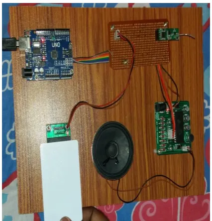
The key components for the project are the zigbee units and APR33A3 voice ic and adruino uno microcontroller.
Fig: APR33A3 VOICE IC
It provides high quality recording and playback with 11 minutes audio at 8 Khz Sampling rate with 16 bit resolution. The aPR33A series C2.x is specially designed for simple key trigger, user can record and playback the message averagely for 1, 2, 4 or 8 voice message(s) by switch, It is suitable in simple interface or need to limit the length of single message.
Available online: https://edupediapublications.org/journals/index.php/IJR/ P a g e | 642
connection, a power jack, an ICSP header, and a reset button.
As said earlier, it contains two units one at the bus stop and the other one inside the bus.the following are the figures of the units.
figa : the unit inside the bus
Fig b:the unit at the bus stop
In the above figures, fig b represents the unit at the bus stop where it gets activated when the user places the card on the reader and a unique number is sent to the controller unit inside the bus where it checks the default
numbers stored inside its register.if the incoming number matches with any of the default numbers then the display unit shown in the fig a, it shows the information related to the incoming number like bus stop name wher the driver acknowledges it with accept and reject buttons then audio clips assigned to the acknowledgements are at the bus stop.
V.RESULTS AND ANALYSIS:
Fig c:user placing card on the reader
Available online: https://edupediapublications.org/journals/index.php/IJR/ P a g e | 643
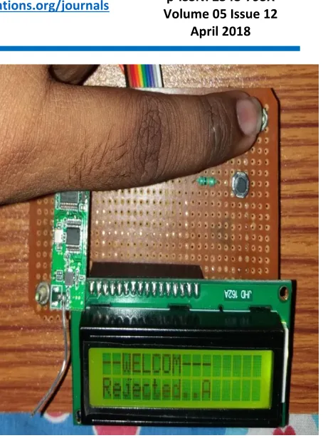
Fig d:A request coming from bus stop – A
The number sent by the unit at the bus stop will be received by a bus unit within the transmission range and displays the a request in the display as shown in the figure d.the above figure is replicating the actions described in the above description.
Fig e: Accepting the request from bus stop – A
Fig f: rejecting the request from bus stop- A
Thus received signal can be acknowledged in two ways, one by accepting the signal by pressing the button assigned to it,the other option is to reject the signal by pressing the another button.In either options an acknowledgement signal is sent tobus stop unit by playing the audio clip like “your bus will arrive in few minutes ”-when the driver accepts the signal and “try again”-when the driver rejects the signal.
In the above figures , fig e represents acceptance of the received signal whereas fig f shows the rejection of the signal.
VI.CONCLUSION:
Available online: https://edupediapublications.org/journals/index.php/IJR/ P a g e | 644
implementing a system which will use the RFID tag and reader setup along with customized program that will help the blind in identifying exact bus. Results of tests indicated that this system could help users to successfully board their desired buses, using the interactive communication modules. Thus showing the possibility of using the RFID technology to help the blind.
VII.REFERENCES:
[1] Bin Ding Sch. of Manage. Univ. of Sci. & Technol. of China, "The Research on Blind Navigation System Based on RFID", ISBN: 978-1-4244-1311-9, Page(s) : 2058 – 2061, 21-25 Sept. 2007.
http://ieeexplore.ieee.org/xpl/articleDetails.jsp ?tp=&arn
umber=4340289&queryText%3Dblind+bus+navi gation +system+using+rfid.
[2]Lavanya G, Preethy W, Shameem A, Sushmitha R, "Passenger BUS Alert System for Easy Navigation of Blind", ISBN: 978-1-4673-4921-5, Page(s): 798 – 802, 20- 21 March 2013. http://ieeexplore.ieee.org/stamp/stamp.jsp?tp =&arnumb er=6529043.