DYADIC GREEN’S FUNCTION OF AN ELEMENTARY POINT SOURCE ABOVE A
PERIODICALLY-DEFECTED-GROUNDED DIELECTRIC SLAB
A. M. Attiya
Microwave Engineering Department Electronics Research Institute
El-Tahreer St., Dokki, Giza, 12622, Egypt
Abstract—A general formulation of Dyadic Green’s function for a point source above a two-dimensional periodic boundary is presented in spectral form. This formulation is simplified by considering only the zero term of the infinite Floquet modes. Then it is applied to obtain the Dyadic Green’s function of a printed source above a dielectric slab with periodically defected ground plane by using a generalized equivalent network of this defected ground plane. This equivalent network is obtained from the reflection coefficients of the defected-grounded slab for different angles of incidence. This network includes equivalent impedances of the periodic surface for both TE and TM incident waves. In addition, it includes coupling impedance between the equivalent TE and TM networks. By determining the generalized equivalent network of the ground plane, the problem of the Green’s function can be formulated by coupled TE and TM transmission line networks.
1. INTRODUCTION
applications it would be required to study the interaction between these synthetic periodic materials and the radiating element which should not be a periodic source. Different approximations based on general equivalent parameters are usually used for studying these problems. For example, Seivenpiper mushroom surface can be replaced by a magnetic conducting surface at certain frequency band [2] and a layer of metamaterial is replaced by double-negative slab with specific negative dielectric constant and negative permeability for a certain frequency [1].
However, such equivalent parameters are usually obtained for certain conditions and they can not be generalized for any source. This was the motivation to introduce more rigorous techniques for simulating an aperiodic source in a periodic medium. Direct solution of the problem by traditional numerical techniques like method of moment and finite difference time domain would be very extensive to take into consideration a large periodic structure which may be used a substrate. On the other hand, a single cell is usually enough to simulate a periodic structure by taking into consideration the periodic boundary condition. However, the aperiodic source does not follow this periodic boundary condition. Thus, the key point of the problem is how to match the periodic boundary condition with aperiodic radiation boundary condition. Up to the best knowledge of the author the feasibility of this problem in FDTD is not available yet. On the other hand, formulation of Green’s functions for a point source above a periodic structure can be a good tool for presenting a rigorous full wave solution for the problem of aperiodic source in a periodic medium by using integral equation representation.
What increases the complexity of the problem is that the diffraction coefficients of the periodic structure due to an arbitrary incident plane wave is not usually a simple problem that can be represented analytically in a closed form. Thus, it would be required first to obtain these infinite diffraction coefficients for each point in the infinite integration separately by using any appropriate numerical technique. This will make the calculation of the Green’s function for any source point and observation point is very time consuming.
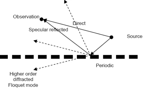
Figure 1. The total field due to an infinitesimal source above a periodic boundary can be represented as a superposition of plane wave in all direction. Each plane wave is diffracted into an infinite set of Floquet modes. The field at the observation point is the summation of the direct field, the specular reflected field and the diffracted fields.
The formulation of dyadic Green’s function for an arbitrary two-dimensional periodic structure is discussed in Section 2. This formulation is based on all the diffracted Floquet modes. However, for most practical applications the periodic boundary has a periodicity less than the half wavelength of the operating frequency. This assumption would introduce that all the higher order Floquet modes are evanescent waves. In addition, the source and the observation points are usually not located on the same plane of the periodic structure as in the case of a periodically defected grounded dielectric slab. Thus, the effect of higher order evanescent Floquet modes can be neglected in this case. This assumption would simplify the problem of the Green’s function to be only infinite spectral integration assuming that only specular diffraction term is the only term considered out of the infinite series of all the Floquet modes. Although this assumption has simplified the problem greatly, it is still required to calculate the specular reflection coefficient of the periodic structure for all spatial spectrum.
Fortunately, such specular reflection can be calculated by using simple equivalent network that can be obtained by fitting the reflections for few angles of incidence [16–21]. Then by applying this equivalent network in the spectral integration, one can obtain the integrand for any spectral point by using simple forms. As an example, the equivalent circuit of the limit case for a complete ground is simply short circuit. The critical point in this method is the accurate representation for the equivalent circuit of the periodic boundary.
Figure 2. General configuration of a periodically-defected-grounded dielectric slab.
The formulation of the equivalent circuit is discussed in Section 3. Section 4 presents numerical examples for the equivalent networks of different periodically defected grounded dielectric slab. These equivalent networks are used to calculate an example of Green’s function of different periodically defected grounded dielectric slabs with an emphasis on their modified features compared with traditionally perfect electrical grounded dielectric slab.
2. FORMULATION OF DYADIC GREEN’S FUNCTION FOR 2-D PERIODIC BOUNDARY
A general formulation for dyadic Green’s function for a point source in the presence of a two-dimensional periodic boundary is discussed in this section based on spectral representation. This representation is based on expanding the field due to an infinitesimal point source as a super position of plane waves in all spectral directions including propagating and evanescent waves as follows [9]:
E(r, r) = −jωµ0Il 8π2
∞
−∞ ∞
−∞
dkx0dky0
¯ ¯I +∇∇
k20
·αe
−jkx0(x−x)−jky0(y−y)−jkz00|z−z| jkz00
(1a)
where
kz00=
k2
r andr are the position vectors of the source and observations points, respectively, ¯¯I is the identity dyadic andαis the direction of the current along the point source.
The total field due a point source in the presence of a specific boundary can thus be obtained by studying the interaction of each plane wave of its spectral representation with the surrounding boundary and adding all the reflected and diffracted field components at the observation point. Calculation of reflected and diffracted waves would require to separate this plane waves according to their polarization into TE and TM components and studying each component separately. For the case of a periodic boundary, the reflected and diffracted fields due to an incident plane wave is represented as an infinite series of Floquet modes that propagate in all directions at discrete spectral points. In addition, for an arbitrary angle of incidence mode coupling can occur due to a periodic boundary. Thus, the incident TE plane wave would be diffracted as TE and TM components and vice versa.
For the case of a horizontal dipole whereα=ax, the radiated field
due to the point source is decomposed into TE and TM components. The total field at the observation point can thus be obtained as
E(r, r) = −Il 8π2ωε
0
∞
−∞ ∞
−∞
dkx0dky0B (kx0, ky0) (2a)
where
B(kx0, ky0) =
k2 0ky0 kρ00kz00
aTEince−jkx0(x−x
)−jky0(y−y)−jkz00|z−z|
+e−jkx0(xd−x)−jky0(yd−y)+jkz00(zd−z)R
TE(kx0, ky0)
+
kx0k0 kρ00
aTMince−jkx0(x−x
)−jky0(y−y)−jkz00|z−z|
+e−jkx0(xd−x)−jky0(yd−y)+jkz00(zd−z)R
TM(kx0, ky0) (2b)
The first terms in each square packet corresponds to the direct wave for both TE and TM components respectively. The unit vectors of the incident TE and TM components are given by:
aTEinc = (ky0ax−kx0ay)/kρ0 (3a)
aTMinc =
sign(z−z)(−kx0ax−ky0ay) +
k2ρ00 kz00
az
kz00 k0kρ00
where sign(x) = 1for x > 0 and sign(x) = −1for x < 0. The
RTE(kx0, ky0) andRTM(kx0, ky0) components correspond to the total reflected and diffracted fields due to the incident TE and TM field components respectively. The general forms of these components for a planar two-dimensionally periodic boundary would be:
RTE(kx0, ky0) =
m
n
aTEref(mn)ΓT E/T Emn +aTMref(mn)ΓT M/T Emn
e−jkxm(x−xd)−jkyn(y−yd)−jkzmn(z−zd) (4a)
RTM(kx0, ky0) =
m
n
aTMref(mn)ΓT M/T Mmn +aTEref(mn)ΓT E/T Mmn
e−jkxm(x−xd)−jkyn(y−yd)−jkzmn(z−zd) (4b)
where the infinite summation represents all Floquet modes,
kxm = kx0+ 2πm/dx (5a)
kym = ky0+ 2πn/dy (5b)
dx anddy are the lattice dimensions inxand ydirections respectively.
The longitudinal propagation constant of themnth Floquet mode is
kzmn =
k20−k2
ρmn Im(kzmn)≤0 (5c)
where
kρmn=
k2
xm+k2yn (5d)
The term Γη/ξmn is the mnth Floquet η diffraction mode due to an ξ
incident plane wave;η andξ here corresponds to either TE or TM. It should be noted that each diffracted ray is starting from the diffraction point given by (xd, yd, zd)
xd = x−(zd−z)kx0/kz00 (6a) yd = y−(zd−z)ky0/kz00 (6b) where zd is the longitudinal position of the interface between the
components in Eq. (2b). The directions of the diffracted TE and TM polarizations are given by
aTEref(mn) = (kynax−kxmay)/kρmn (7a)
aTMref(mn) =
−kxmax−kynay+
k2 ρmn kzmn az kzmn
k0kρmn
(7b)
By applying Eqs. (3)–(7) into Eq. (2), one can obtain the total field at the observation point in all direction due to an infinitesimal point source directed in xdirection. By specifying the received field in each direction separately, one obtains the dyadic componentsGEJxx,GEJyx and GEJzx respectively. As an example, the GEJxx is given by:
GEJxx(r, r) = −1 8π2ωε
0 ∞ −∞ ∞ −∞
dkx0dky0Bx(kx0, ky0) (8a)
where
Bx(kx0, ky0)
=
k02ky0 kz00kρ00
(ky0/kρ00)e−jkx0(x−x
)−jky0(y−y)−jkz00|z−z|
+e−jkx0(xd−x)−jky0(yd−y)+jkz00(zd−z)R
TEx(kx0, ky0)
+
kx0k0 kρ00
kx0kz00 kρ00k0
e−jkx0(x−x)−jky0(y−y)−jkz00|z−z| +e−jkx0(xd−x)−jky0(yd−y)+jkz00(zd−z)R
TMx(kx0, ky0) (8b)
RTEx(kx0, ky0)
=
m
n
(kyn/kρmn) ΓT E/T Emn +
−kxmkzmn
kρmnk0
ΓT M/T Emn
e−jkxm(x−xd)−jkyn(y−yd)−jkzmn(z−zd) (8c) RTMx(kx0, ky0)
=
m
n
−kxmkzmn
kρmnk0
ΓT M/T Mmn + (kyn/kρmn) ΓT E/T Mmn
e−jkxm(x−xd)−jkyn(y−yd)−jkzmn(z−zd) (8d)
For the case of a vertical dipole whereα =az, the radiated field
due to the point source is decomposed TM component only. The total field at the observation point is obtained as
E(r, r) = −ωµ0Il 8π2k2
0
∞
−∞ ∞
−∞
dkx0dky0A(kx0, ky0) (9a)
where
A(kx0, ky0)=
k 0kρ00 kz00
aTMince−jkx0(x−x
)−jky0(y−y)−jkz00|z−z|
+e−jkx0(xd−x)−jky0(yd−y)+jkz00(zd−z)R
TM(kx0, ky0) (9b)
The definitions for all terms ofA(kx0, ky0) are the same as in Eqs. (3)–
(7).
The main problem in this case is how to obtain simple forms of RTE(kx0, ky0) and RTM(kx0, ky0) components for all values of kx0 and ky0. For the case where the source and observation points are slightly separated from the periodic surface as in periodically defected grounded slab and the periodicity of the cells is smaller than the free space half wavelength, the higher order modes will be evanescent and decaying waves. Thus, the problem can be approximated by considering only the zero order Floquet mode in the infinite series representation of RTE(kx0, ky0) and RTM(kx0, ky0). Hence, it is required only to calculate the specular reflection coefficients only including the mode conversion between the TE and TM fields. Although this approximation represents a great simplification for the problem, the direct calculation of the required reflection coefficients at all values ofkx0andky0 is still an enormous computational aspect that cannot be suitable for direct calculation of the corresponding Green’s function. This is the motivation here to develop approximate forms for these reflection coefficients based on calculated values at few kx0 and ky0 points.
A final note before ending this section is that the double infinite integration can be simplified by converting it into a polar form to make use of any symmetric property in the radial direction. Thus, the
integration ∞
−∞ ∞
−∞dkx0dky0 would be replaced by
2π
0
∞
0
kρdkρdφ where
3. EQUIVALENT NETWORK OF A PERIODICALLY DEFECTED GROUNDED DIELECTRIC SLAB
For a grounded dielectric slab, the longitudinal field dependence can be modeled by two separated transmission line sections for both TE and TM modes where the free space is modeled by a semi-infinite transmission line section and the grounded dielectric slab is modeled by a short-circuited finite transmission line section. In this case the other half space is completely isolated by the perfect electric conductor and there is no coupling between the TE and TM modes. This model can be modified for a periodically-defected-grounded dielectric slab by replacing the short circuit by finite impedance and introducing additional coupling impedance between the equivalent TE and TM networks. In this case the lower semi-infinite half is not isolated as in the case of a grounded dielectric slab. Figure 3 shows the proposed general equivalent network for an incident TE wave. In this case the periodic structure is modeled by the impedance ZsT E and the mode coupling between the TE and TM fields is modeled by the impedance
Figure 3. Equivalent network that can be used to model the reflection and transmission coefficients due to an incident TE plane wave on a periodically defected grounded dielectric slab. Z0T E =ωµ/kz0,Z1T E = ωµ/kz1, Z0T M = kz0/ωε0, Z1T M = kz1/ωε0εr. kz1 =
εrk20−k2ρ and
kz0 =
k20−k2
ρ = k0cosθinc, kρ = k0sinθinc. ZsT E and Z T M/T E s
ZsT M/T E. For the case of low coupling between TE and TM fields, this
coupling impedance would be open circuit.
In this case the equivalent network would be excited from the upper semi-infinite TE transmission line. The reflected field along this line would correspond to ΓT E/T E while the transmitted field to the lower semi-infinite TE transmission line would correspond to TT E/T E. On the other hand, the transmitted fields through the coupling impedance to the upper and lower semi-infinite TM transmission lines would correspond to ΓT M/T E and TT M/T E respectively. By using simple transmission line calculations one can obtain these reflection and transmission coefficients in terms of the equivalent impedance parameters as follows
ΓT E/T E =
jZ1T E 2
−Z0T E 2
ZsT Etankz1d
+jZ1T E2Z0T Etankz1d−
Z0T E2Z1T E
2Z1T EZsT EZ0T E+jZ1T E
2+ZT E
0 2
ZsT Etankz1d
+jZ1T E 2
Z0T Etankz1d+
Z0T E2Z1T E
(10a)
ΓT M/T E = Z
T M
in //Z0T M
ZsT M/T E+ZinT M//Z0T M
ejkz0d+ ΓT Ee−jkz0d
(ejkz1d+ Γse−jkz1d)
(1+ Γs)
1 + ΓT M
01
ejkz1d+ ΓT M
01 e−jkz1d
(10b)
TT E/T E =
ejkz0d+ ΓT E/T Ee−jkz0d
(ejkz1d+ Γse−jkz1d) (1+ Γs) (10c)
TT M/T E = Z
T M
in //Z0T M
ZsT M/T E+ZinT M//Z0T M
ejkz0d+ ΓT E/T Ee−jkz0d
(ejkz1d+ Γse−jkz1d) (1+ Γs) (10d) where
ZinT M =Z1T MZ
T M
0 +jZ1T Mtankz1d Z1T M +jZ0T Mtankz1d
(11a)
Γs=
ZsT E//Z0T E−Z1T E ZT E
s //Z0T E+Z1T E
ZsT E =−
ΓT E/T E+ 1 Z0T E 2
Z1T E
+j
ΓT E/T E−1 Z1T E 2
Z0T Etankz1d
2Z1T EZ0T EΓT E/T E+j
Z0T E
2ΓT E/T E+1tank z1d
+ jZT E
1 2
ΓT E/T E−1tank z1d
(11c)
ΓT M01 = Z
T M
0 −Z1T M
Z0T M +Z1T M (11d)
For the inverse problem, where it is required to obtain the equivalent impedance parameters from the reflection coefficients, it can be shown that:
ZsT M/T E=
X−ΓT M/T E ΓT M/T E
ZinT M//Z0T M (12a)
ZsT E= Z
T E
s ZT M
(ZT M −ZT E
s )
(12b)
where
X=
ejkz0d+ ΓT Ee−jkz0d
(ejkz1d+ Γ
se−jkz1d)
(1+Γs)
1 + ΓT M
01
ejkz1d+ ΓT M
01 e−jkz1d
(13a)
ZT M=ZsT M/T E+Z0T M//ZinT M (13b)
The problem now is converted into obtaining the reflection coefficients ΓT E/T E and ΓT M/T E for the periodically defected grounded dielectric slab at different values ofkx0andky0by using an appropriate technique like method of moment [16–19, 27] or by using experimental data. The results in the present paper are based on obtaining these reflection coefficients by using method of moment. These reflection coefficients are used in Eqs. (11)–(13) to obtain the corresponding values ofZsT E and ZsT M/T E by using Eq. (12) at these values ofkρ and φ.
For periodical structures of very small cell compared with the operating wavelength, these equivalent impedances are found to be nearly independent on kρ and φ. Thus, they can be represented as
fixed impedances in this case. However, these equivalent impedances are found to be slightly varying at different values of kρ and φ for
periodic cell less than half free space wavelength. By applying these equivalent impedances into Eq. (11), one can obtain the reflection and transmission coefficients of Eq. (10) at all the spectral plane including the visible and the non-visible regions. By using these reflection coefficients it would be possible to calculate the dyadic Green’s function of a point source above periodically defected ground plane as discussed in the previous section.
Equations (10)–(13) are derived for TE incident wave. Similar analysis is also obtained for TM incident wave. By analogy, the resultant equations for TM case is the same as TE case after exchanging all TE and TM superscripts in Eqs. (10)–(13).
4. NUMERICAL EXAMPLES
This section introduces sample results for the equivalent networks of different periodically defected grounded dielectric slabs. Then theses equivalent networks are used to calculate the Green’s function Gxx
as an example for the dyadic Green’s function. The dielectric slab is assumed to be of a thickness h = 1.575 mm and a dielectric constant εr = 1 0.2. The operating frequency is assumed to 10 GHz. The
unit cell of the periodic defected ground slab in the present examples is assumed to be square of length 9 mm which is 0.3 the free space wavelength at this operating frequency.
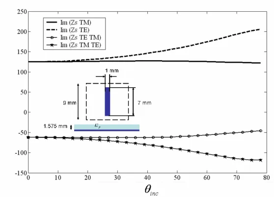
As a simple example for this defected grounded slab is an array of strips of dimensions 7 mm×1mm. The strips are assumed to be oriented parallel to they axis. The maximum mode conversion in this case can be obtained at φinc = π/4. Figure 4 shows the equivalent
network parameters in this case for different values ofθinc. It can be
noted that the equivalent impedances for both TE and TM incident waves are purely inductive while the coupling impedances are purely capacitive.
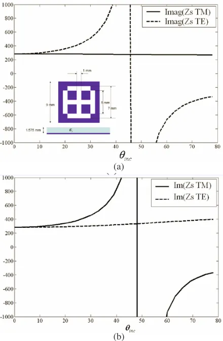
In a similar way, the equivalent network of a periodically defected ground slab composed of Jerusalem cross slots and patches are obtained as shown in Figures 5 and 6. The advantage of this shape is the symmetry in the different φ directions. This symmetry reduces the coupling effect between the TE and TM waves. Thus, the coupling impedances in this case are found to be nearly open circuit. It is also noted that the equivalent network of periodically defected of Jerusalem cross slot is characterized by resonance behavior. This resonance behavior is not found in the periodically defected of Jerusalem cross patches where both the equivalent TE and TM networks are found to be capacitive for all scanning angles.
Figure 4. Equivalent network parameters at 10 GHz for a periodically defected grounded dielectric slab as functions ofθincwhereφinc=π/4.
The unit cell of the defected ground plane is a square lattice of dipole FSS. The lattices dimensions are 9 mm×9 mm. The dipole FSS is 7 mm×1mm. The thickness of the dielectric slab is 1.575 mm and its dielectric constant is 10.2.
functionGxx(x, y, z;x, y, z) for an infinitesimal point source above a
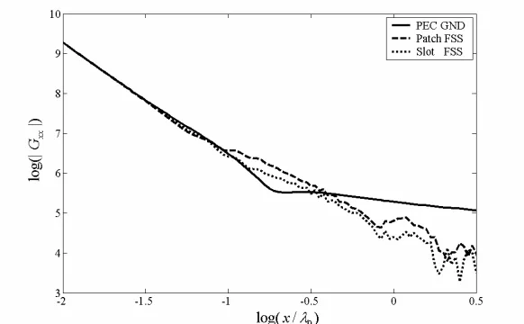
blindness in infinite phase array of such printed antennas which are undesirable properties in this type of antennas. On the other hand, one can not that for periodically defected ground plane, the decay rate is slightly different from 1/x3, which means that the surface wave effect in this case would be negligible. This important feature is found for both patch and slot FSS ground planes, however slot FSS ground plane is found to have more effect on reducing the mutual coupling between the source and the observation point above the slab. This result shows that periodically defected ground plane can be a good candidate for printed antenna applications.
(a)
(b)
Figure 5. Equivalent network parameters at 10 GHz for a periodically defected grounded dielectric slab as functions ofθincwhere (a) φinc=
Figure 6. Equivalent network parameters at 10 GHz for a periodically defected grounded dielectric slab as functions ofθincwhereφinc=π/2.
Figure 7. The Green’s functionGxx(x,0, h; 0,0, h) of a point source
5. CONCLUSION
Dyadic Green’s function of an infinitesimal point source above a periodically-defected dielectric slab is formulated in spectral form. This spectral form includes all the diffracted Floquet modes. It is simplified for small periodic cells by using only the zero order mode where all the higher order modes are evanescent modes. This spectral representation is based on the reflection and mode coupling coefficients of the periodically-defected ground dielectric slab. These reflection and mode coupling coefficients can be obtained analytically in closed forms by using equivalent loaded transmission line sections. An efficient technique is used to obtain the equivalent network parameters of the periodically-defected grounded dielectric slab by using the calculated reflection and mod coupling confections at discrete angles of incidences. These equivalent networks are used to obtain these coefficients at any angle of incidence analytically. Examples of the equivalent network parameters are presented for different periodically-defected grounded dielectric slabs. These equivalent networks are used to calculate the Green’s functions for these slabs. It is found that such periodically defected ground plane has an efficient effect on reducing surface wave coupling between the source and the observation points on the dielectric slab. This feature has a significant importance in designing large printed phased array antennas to avoid scan blindness.
REFERENCES
1. Enghata, N. and R. W. Ziolkowski, Electromagnetic Metamateri-als: Physics and Engineering Exploration, Wiley-IEEE, 2006. 2. Sievenpiper, D., L. Zhang, R. F. Broas, N. G. Alexopoulos, and
E. Yablonovitch, “High-impedance electromagnetic surface with a forbidden frequency band,”IEEE Trans. Microwave Theory Tech., Vol. 47, 2059–2074, Nov. 1999.
3. Kildal, P. S., “Artificially soft and hard surfaces in electromag-netics,” IEEE Trans. Antennas Propagat., Vol. 38, 1537–1544, Oct. 1990.
4. Zhang, J. Y., J. Y. von Hagen, M. Younis, C. Fischer, and W. Wiesbeck, “Planar artificial magnetic conductors and patch antennas,” IEEE Trans. Antennas Propagat., Special Issue on Metamaterials, Pt. I, Vol. 53, 70–81, Jan. 2005.
6. Melezhik, P., A. Poyedinchuk, and N. Yashina, “Radiation from surface with periodic boundary of metamaterials excited by a current,” Progress In Electromagnetics Research, PIER 65, 1–14, 2006.
7. Oskouei, H. D., K. Forooraghi, and M. Hakkak, “Guided and leaky characteristics of periodic defected ground structures,”Progress In Electromagnetics Research, PIER 73, 15–27, 2007.
8. Terracher, F. and G. Berginc, “A numerical study of TM-type surface waves on grounded dielectric slab covered by a doubly periodic array of metallic patches,”Progress In Electromagnetics Research, PIER 43, 75–100, 2003.
9. Chew, W. C., Waves and Fields in Inhomogeneous Media, Van Nostrand Reinhold, New York, 1990.
10. Sigelmann, R. A. and A. Ishimaru, “Radiation from aperiodic structures excited by an aperiodic source,”IEEE Trans. Antennas Propagat., Vol. 13, 354–364, May 1965.
11. Yang, H. Y. D. and J. Wang, “Surface waves of printed antennas on planar artificial periodic dielectric structures,” IEEE Trans. Antennas Propagat., Vol. 49, 444–450, Mar. 2001.
12. Yang, H. Y. D., “Theory of microstrip lines on artificial periodic substrates,” IEEE Trans. Antennas Propagat., Vol. 47, 629–635, May 1999.
13. Capolino, F., D. R. Jackson, D. R. Wilton, and L. B. Felsen, “Comparison of methods for calculating the field excited by a dipole near a 2-D periodic material,” IEEE Trans. Antennas Propagat., Special Issue on Electromagnetic Waves in Complex Environments: A Tribute to Leopold B. Felsen, Vol. 55, 1644– 1655, Jun. 2007.
14. Capolino, F., D. R. Jackson, and D. R. Wilton, “Fundamental properties of the field at the interface between air and a periodic artificial material excited by a line source,” IEEE Trans. Antennas Propagat., Special Issue on Artificial Magnetic
Conductors, Soft/Hard Surfaces, and Other Complex Surfaces,
Vol. 53, 91–99, Jan. 2005.
15. Qiang, R., J. Chen, F. Capolino, D. R. Jackson, and D. R. Wilton, “ASM-FDTD: A technique for calculating the field of a finite source in the presence of an infinite periodic artificial material,”
IEEE Microw. Wireless Compon. Lett., Vol. 17, No. 4, 271–273, Apr. 2007.
16. Whites, K. W. and R. Mittra, “An equivalent boundary-condition model for lossy planar periodic structures at low frequencies,”
17. Stufel, B. and Y. Pion, “Impedance boundary conditions for finite planar and curved frequency selective surfaces,” IEEE Trans. Antennas Propagat., Vol. 53, 1415–1425, Apr. 2005.
18. Stufel, B., “Impedance boundary conditions for finite planar or curved frequency selective surfaces embedded in dielectric layers,”
IEEE Trans. Antennas Propagat., Vol. 53, 3654–3663, Nov. 2005. 19. Munk, B. A., Frequency Selective Surfaces: Theory and Design,
John Wiley & Sons, New York, 2000.
20. Dubrovka, R., J. Vazquez, C. Parini, and D. Moore, “Equivalent circuit method for analysis and synthesis of frequency selective surfaces,”IEE Proc. - Microw. Antennas Propag., Vol. 153, No. 3, 213–220, Jun. 2006.
21. Maci, S., M. Caiazzo, A. Cucini, and M. Casaletti, “A pole-zero matching method for EBG surfaces composed of a dipole FSS printed on a grounded dielectric slab,” IEEE Trans. Antennas Propagat., Vol. 53, 70–81, Jan. 2005.
22. Yang, H. Y. D., N. G. Alexopoulos, and E. Yablonovitch, “High-gain printed circuit antennas,”IEEE Trans. Antennas Propagat., Vol. 45, 185–187, Jan. 1997.
23. Lynch, J. J. and J. S. Colburn, “Modeling polarization mode coupling in frequency-selective surfaces,”IEEE Trans. Microwave Theory Tech., Vol. 52, 1328–1338, Apr. 2004.
24. Bilotti, F., L. Vegni, and F. Viviani, “Spectral dyadic Green’s function of integrated structures with high impedance ground plane,” Journal of Electromagnetic Waves and Applications, Vol. 17, No. 10, 1461–1484, 2003.
25. Yang, H. Y. D. and D. R. Jackson, “Theory of line-source radiation from a metal-strip grating dielectric-slab structure,”IEEE Trans. Antennas Propagat., Vol. 48, 556–564, Apr. 2000.
26. Munk, B. A. and G. A. Burrell, “Piecewise linear elements and its application in determining the impedance of a single linear antenna in a lossy half-space,” IEEE Trans. Antennas Propagat., Vol. 27, 331–343, May 1979.