1
Theoretical Approach of Downsizing 2L V6 Petrol
Engine to 4 Cylinder Inline Engine
Rishabh Pravin Bafna
Department of Mechanical Engineering, Jaihind College of Engineering, Kuran Email: [email protected]
Abstract- The paper discusses the concept, design and final results of downsizing 2L V6 Petrol engine to 4 cylinder inline (I4) engine. The basic architecture is retained and prime importance is given to meet the Indian market performance requirement, which was done by having strong focus on fuel economy, power & cost. The paper discusses the technologies which can be implemented for the purpose of downsizing so that the 4 cylinder inline engine has equal power or more power than the 2L V6 petrol engine. Mostly downsizing doesn't mean that just reducing the number of cylinders. Downsizing is done to reduce the capacity of engine, without affecting the power delivered by the engine. The paper discusses the theoretical calculations done for designing I4 engine & with the use of proposed technologies we can create a downsized I4 engine as good as a V6 engine.
Index Terms- Petrol Engine, Downsizing
1. INTRODUCTION
The purpose of this project is to produce a downsized 4 cylinder inline engine from a 2L V6 petrol engine. As diesel is cheaper, we can develop a downsized 4 cylinder inline diesel engine suited to Indian market performance. But we are going to present the theoretical concept of developing the engine based on the same architecture of a 2L V6 petrol engine. Hence, we will be developing a downsized 4 cylinder petrol engine. The main problem raised was whether we can achieve the same or better performance by integrating a smaller engine into our machines. This is the fundamental question that underpins the steady increase in Original Equipment Manufacturers (OEMs) looking at engine downsizing as a way of improving the cost-effectiveness of their operations. With a growing number of OEMs choosing to install more compact and efficient engines into their machines, the benefits of engine downsizing are becoming more apparent. By integrating a smaller displacement engine, operators can benefit from a reduction in fuel burn and lower greenhouse gas emissions, while higher power density helps to improve the overall efficiency of smaller engines. If a car has a smaller capacity engine than its predecessor, but can still do the same job or has even better performance, then we call it „downsizing‟.
Engine downsizing is the use of a smaller engine in a vehicle that provides the power of a larger engine, through the use of recent technologies.
Mostly downsizing doesn't mean that just reducing the number of cylinders. Downsizing is done to reduce the capacity of engine, without affecting the power delivered by the engine.
It is the result of car manufacturers attempting to provide more efficient vehicles that emit less emission.
Many manufacturers are reducing engine capacity and number of cylinders. By adding a boosting device (turbocharger or supercharger) and direct injection technology, they provide a powerful engine with similar performance to a much larger engine, but with much improved efficiency and reduced carbon emissions.
A smaller engine is also often lighter, so the car can be lighter and therefore nimbler. Reducing the number of cylinders also reduces the amount of friction in the engine, increasing the efficiency.
Downsizing by adding a turbocharger or tuning the engine to have better exhaust system, racing air filters and remapping ECU to inject more fuel, so it‟s a petrol engine, you can use better racing spark plugs.
2
2. COMPARISON TABLE (BENCHMARKING)
Nissan Cefiro A32 has Bosch double platinum spark plugs, 4 valves per cylinder (2 for inlet & 2 for exhaust). It has a Double OverHead Camshaft (DOHC) with Variable Valve Timing (VVT). Multi Point Fuel Injection (MPFI) system is equipped in this car.
The above mentioned I4 cars have a total of 16 valves (4 valves per cylinder). Multi Point Fuel
Injection (MPFI) system is equipped in almost all of them. Toyota Corolla XI (E170) has 1 spark plug per cylinder & the rest of the models have 2 spark plugs per cylinder each. All models have turbocharger but Volkswagen Golf V has both turbocharger & supercharger.
Specifications Ford Ecosport Volkswagen Golf V
Toyota Corolla XI
(E170) Renault Fluence
Nissan Cefiro A32
Engine Model DURATEC
Ti-VCT 1.4 TSI 1.6 Valvematic 1.6 16V VQ20DE
Bore 79mm 76mm 80.5mm 79.5mm 78mm
Stroke 81.4mm 75.6mm 78.5mm 80.5mm 69.7mm
No. of cylinders 4 (inline) 4 (inline) 4 (inline) 4 (inline) 6(V engine)
Displacement 1499cc 1390cc 1598cc 1598cc 1995cc
Compression
Ratio 11.0:1 10.0:1 10.7:1 9.8:1 9.5:1
Maximum Power 112hp@
6300rpm
140hp@ 5600rpm
132hp@ 6400rpm
110hp@ 6000rpm
155hp@ 6400rpm
Maximum Torque 140N.m@
4400rpm
220N.m@ 4000rpm
160N.m@ 4400rpm
151N.m@ 4250rpm
186N.m@ 4400rpm
Top Speed 172kmph 210kmph 200kmph 185kmph 227kmph
Mileage
12.3kmpl (city) 19.2kmpl (highway)
12kmpl (city) 19.6kmpl (highway)
12.5kmpl (city) 20.4kmpl (highway)
12kmpl (city) 14kmpl (highway)
10kmpl(city) 14.1kmpl (highway)
0-100 acceleration
(sec) 13.3 8.8 10 11.5 9.2
Transmission 5MT 6MT 6MT 5MT 5MT
3
3. DESIGNOFPARAMETERS
Let
Car 1 = Ford Ecosport
Car 2 =
Volkswagen Golf V
Car 3 =
Toyota Corolla XI (E170)
Car 4
= Renault Fluence
Car 5 =
Nissan Cefiro A32
We have Bore Diameter, d We have Stroke Length, L
Displacement volume of single cylinder, V = Vs = (3.14/4) * d2 * L
Total displacement volume of 4 cylinders, Vt = Vs t= 4 * V
We have Compression Ratio, CR CR = (Vc + Vs) / Vc
where Vc = Clearance Volume & Vs = Stroke Volume
We get the value of Vc from above equation.
By following the above procedure, we get the values of V, Vt, Vc for the mentioned cars.
Table 1: Volumes of cars (in cc)
Car 1
Car 2
Car 3
Car 4
Car 5
V
398.99 342.95 399.53 399.59 333.05Vt
1595.96 1371.8 1598.12 1598.36 1332.2Vc
39.89 38.10 41.19 45.41 39.18We took the average of Vc of 4 cars. We get (Vc)avg = 41.14
Based on (Vc)avg value, we find the value of CR. Table 2: Compression ratio of cars
Car 1
Car 2
Car 3
Car 4
CR 10.69 9.34 10.71 10.71 We select the precise value, i.e., CR = 10.71
Brake Power = (2*3.14*N*T) / 60
1 hp = 746 W Therefore, 1 W = (1 / 746) hp Table 3: Break horse power of cars (in hp)
Car 1 Car 2 Car 3 Car 4 Car 5
bhp
86.47 123.53 98.82 90.08 114.88We take the average of the brake horse power (bhp) of the 4 cylinder inline petrol engine cars. We get (bhp)avg = 99.59hp ~ 100hp = 74600W
We select the values closer to Volkswagen golf V because the bhp of this car is maximum among the other three 4 cylinder inline petrol engine cars. We take the following values for the design of a downsized 4 cylinder inline engine:
Bore Diameter, d = 77mm Stroke Length, L = 76mm V = Vs = (3.14/4) * d2 * L We get V = Vs = 353.90cc Vt = Vst = 4 * V
We get Vt = Vst = 1415.6cc ~1416cc
Thus, we downsized the 2L V6 petrol engine to 1.4L 4 cylinder inline petrol engine.
Compression Ratio, CR = 10.71 CR = (Vc + Vs) / Vc
We get Vc = 36.45cc
Torque is inversely proportional to rpm. Hence, we take Torque * rpm = Constant.
We find the torque values of all the mentioned cars at 4400rpm.
Table 4: Torque of cars (in N.m)
Car 1
Car 2
Car 3
Car 4
Torque 140 200 160 145.85
We took the average value of the torque of the first 4 cars. We get
Average Torque = 161.46 N.m Brake Power = (2*3.14*N*T) / 60 We get bhp = 99.72hp
Thus, the theoretically obtained bhp of a 4 cylinder inline petrol engine is 99.72hp.
4 The value of the brake horse power of 4 cylinder
[image:4.595.306.520.135.514.2]inline engine (before downsizing) is very much closer to the brake horse power of a 2L V6 petrol engine. Now, after equipping some better technologies, we can further increase the power of the 4 cylinder inline petrol engine.
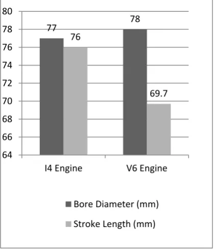
[image:4.595.73.283.213.457.2]Fig. 1: Bore diameter (mm) & Stroke length (mm) of I4 & V6 engine
Fig. 2: Displacement volume (cc) of I4 & V6 engine
Fig. 3: Compression Ratio of I4 & V6 engine
Fig. 4: Maximum torque (N.m) & maximum power (hp) of I4 engine before downsizing & V6 engine at 4400rpm
4. PROPOSED TECHNOLOGIES
4.1.Fuel Injection Technologies:
4.1.1. Gasoline Direct Injection (GDI):
In non-Diesel internal combustion engines, Gasoline Direct Injection (GDI), also known as Petrol Direct Injection, Direct Petrol Injection, Spark Ignited Direct Injection (SIDI) and Fuel Stratified Injection (FSI), is a variant of fuel injection employed in modern two-stroke and four-two-stroke gasoline engines. The gasoline is highly pressurized, and injected via a common rail fuel line directly into the combustion chamber of each cylinder, as opposed to conventional multi-point fuel injection that injects fuel into the intake tract, or cylinder port. Directly injecting fuel into the combustion chamber requires high pressure injection whereas low pressure is used injecting into the intake tract or cylinder port.
77 78
76
69.7
64 66 68 70 72 74 76 78 80
I4 Engine V6 Engine
Bore Diameter (mm)
Stroke Length (mm)
1416 1995
0 1000 2000 3000
I4 Engine V6…
Displacement (cc)
10.71 9.5
8.5 9 9.5 10 10.5 11
I4 Engin
e V6 Engin
e
Compression Ratio
161.46
186
99.72 114.88
0 20 40 60 80 100 120 140 160 180 200
I4 Engine Before Downsizing
V6 Engine
Maximum Torque at 4400rpm (N.m)
[image:4.595.74.284.496.640.2]5 In some applications, gasoline direct injection enables
stratified fuel charge (ultra-lean burn) combustion for improved fuel efficiency, and reduced emission levels at low load.
4.1.2. Multi Point Fuel Injection (MPFI):
MPFI is a fuel injection technique used in gasoline engines. MPFI injects fuel into the intake ports of each cylinder‟s intake valves, rather than at central point within an intake manifold like in spark plugs.
Direct Injection has a lot of advantages over the MPFI or port injection and it‟s the way of the future.
Direct injection improves mileage through a stratified charge engine process.
Lower emissions.
Prevents engine knocking/detonation.
Better control of the engine since before GDI it was only possible to manipulate valve timings in
real time operation to change the
efficiency/power characteristics of the engine, now since you can vary the fuel pressure, amount, there are a whole lot of possibilities to explore.
GDI engines are built sturdier compared to MPFI engines and last longer.
Better power output compared to MPFI.
The ultimate advantage of GDI is that through this technology everything happening inside the engine can be precisely controlled by the electronics and nothing is left to chances. For example in MPFI, some amount of fuel can be left over inside the injectors though not causing an issue , causes slight variation in every stroke but when you move over to GDI , it‟s like a German train time table. It will always be perfect. Hence, we are implementing GDI technology.
4.2.Valve Operating Mechanisms:
There are various technologies available in the market for valve opening& closing mechanism as follows:
VVT: Variable Valve Timing VTVT: Variable Timing Valve Train
VVTi: Variable Valve Timing with intelligence
iVTEC: Intelligent Valve Lift Technology
& many more similar technologies.
The above mentioned technologies are used mechanically. Hence, there are friction losses.
Brake Power = Indicated Power – Friction Losses
Hence, to increase the brake power, we need to reduce the friction losses. To reduce friction losses, we are implementing an electronically operated solenoid valve for operating intake & exhaust valves. As we use a hydraulic system, there is no need to use cam shaft & timing belt or timing chain.
4.3.Turbocharger:
There are various types of turbocharger. Some of them are as follows:
Normal Turbocharger
Variable Nozzle Turbocharger Waste Gate Turbocharger Two Stage Turbocharger Three Stage Turbocharger
We are implementing a Two Stage Turbocharger (Twin Type Turbocharger) in a 4 cylinder inline petrol engine along with an intercooler in between because with the help of such kind of arrangement, we can send more amount of air inside the cylinder. Turbocharger will suck the atmospheric air in its first stage. Then the pressure air rises, & according to Charles law, pressure is directly proportional to the temperature. Thus, temperature rises & then the density also rises. Now, if we pass this pressurized air into the intercooler, then its density will decrease. Again pass the air to the second stage of compressor & then ultimately send it to the IC engine. Thus, we can send more amount of air by this arrangement. This ultimately results in efficient combustion of fuel.
4.4.Camshaft & Cam Quantity:
If the number of inlet & exhaust valves is 1 each in a single cylinder, then we can use a Single Over Head Camshaft (SOHC).
If the number of inlet & exhaust valves is 2 each in a single cylinder, then we can use a Double Over Head Camshaft (DOHC).
The more are the number of valves, the more are the number of cams required for operating the valves. We are using 16 valves in total.
6
4.5.Exhaust Gas Recirculation (EGR):
4.5.1. High Pressure EGR:
Low EGR rates at lower engine speeds/loads Simple to calibrate
Cheaper
4.5.2. Low Pressure EGR:
Higher EGR rates
Possible damage to engine Complicated to calibrate Expensive
4.5.3. High + Low Pressure EGR:
Higher EGR rates More flexibility in control Complicated to calibrate Expensive
We are selecting High + Low Pressure EGR because according to the conditions, the respective EGR will process the exhaust gas.
4.6.Spark Plug:
Single Spark Plug Dual Spark Plug
Triple Spark Plug – One Master Plug & Two Slave Plugs
When we are using all the advanced technologies, then there is no need to use a triple spark plug. Dual spark plug is sufficient enough to create complete combustion of the fuel inside the combustion chamber & cylinder. Hence, we use dual spark plug.
4.7.Catalytic Converter:
4.7.1. Two way catalytic convertor: Reactions:
Oxidation of carbon monoxide to carbon dioxide: 2CO + O2 → 2CO2
Oxidation of hydrocarbons (unburnt and partially burnt fuel) to carbon dioxide and water:
CxH2x+2 + [(3x+1)/2] O2 → xCO2 + (x+1) H2O
4.7.2. Three way catalytic convertor: Reactions:
Oxidation of carbon monoxide to carbon dioxide: 2CO + O2 → 2CO2
Oxidation of hydrocarbons (unburnt and partially burnt fuel) to carbon dioxide and water:
CxH2x+2 + [(3x+1)/2] O2 → xCO2 + (x+1) H2O Reduction of nitrogen oxides to nitrogen and oxygen: 2NOx → xO2 + N2
We are using the three way catalytic convertor because it reduces nitrogen oxides also.
Alternative to this problem is that we can use „Nano fluid‟ as a coolant which doesn‟t allow the production of NOx & SOx in the cylinder after combustion. Beyond a particular higher temperature (1100oC), NOx & SOx gases are produced. The Nano fluid (Alumina- Al2O3), as a coolant doesn‟t allow this temperature to be reached. So, there is no production of NOx & SOx.
5. CONCLUSION
Thus, we are able to develop a 4 cylinder inline engine which has a closer value of brake power to that of a 2L V6 petrol engine. Later, to increase further the brake power of the 4 cylinder inline engine, we equipped the engine with various technologies. We installed a Gasoline Direct Injection (GDI) system, iVTEC valve operating mechanism, Two Stage Turbocharger, 4 valves per cylinder (2 inlet valves & 2 exhaust valves), Double Over Head Camshaft (DOHC), High + Low Pressure EGR, Double Spark Plug (Twin Spark Ignition System), Three Way Catalytic Convertor, etc.
We can even install an electronically operated solenoid valve instead of iVTEC & DOHC so that friction losses occurring by the mechanical valve operating mechanism & Double Over Head Camshaft (DOHC) is reduced. The problem with this technique is the increase in cost of the engine.
There is no need to install a supercharger. The above mentioned technologies are sufficient to downsize a 2L V6 petrol engine into a 4 cylinder inline petrol engine.
6. ACKNOWLEDGEMENT
1. I would like to thank Expertshub (Industrial Skill Development Centre) for giving me a platform to improve my technical knowledge & skills regarding automobiles & for making me trained to assemble & disassemble various types of engines.
2. I express my sincere regards to Mr. Kirubakaran Reddy & his entire team for guiding me regarding this paper topic. 3. I would like to thank Prof. Mosim Attar for
7
7. REFERENCE
[1] Ajinkya Deshmukh & Abhishekh Borse; “A Review on Advanced Engines Technology” International Journal of Advanced Technology in Engineering & Science, Vol. No. 4, Issue No. 02, February, 2016, pp. 85 – 89
[2] Carlo Alberto Rinaldini, Sebastiano Breda, Stefano Fontanesi,Tommaso Savioli; “Two -Stage Turbocharging for the Downsizing of SI V-Engines”, 69th Conference of the Italian Thermal Engineering Association, ATI 2014; 2015; pp. 716-722
[3] M Suresh, Dr. R. Hari Prakash, Dr. B Durga Prasad; “Operation and Developments of DISI Engines – A Review”, International Journal of Latest Trends in Engineering and Technology (IJLTET), Vol. 5 Issue 4 July 2015, pp. 31-37
[4] Tejas B. Raju, DoddamaniHithaish; “A Review
on Gasoline Direct Injection Engine System”, International journal of research in aeronautical and mechanical engineering, Vol.2, Issue.3, March 2014, pp. 224-231
[5] G.V.N.B.Prabhkar , B.Kiran Babu , K.Durga Prasad; “Digital Twin and Triple Spark Ignition in FourStroke Internal Combustion Engines of TwoWheelers”, International Journal of Innovations in Engineering and Technology (IJIET), Volume 4 Issue 4 December 2014, pp. 293-298