`
1.INTRODUCTION
T
he auto industry faced with the growing challenges to fulfill ever growing demands of today global customer, which puts a great pressure on the automotive R&D & test engineers to develop a critical component in the shortest possible time to minimize the launch time for new products. This necessitates the understanding of the new technologies & quick absorption of the development of the newer products. The main objective of this research work is the design evaluation of automobile connecting rod using FEM for high cycle fatigue strength. The main concern is to perform structural dynamic analysis of the connecting rod to cross check its failure by FEA. The pre-processing and analysis is performed using high end latest software. The connecting rod is under tremendous stress from the reciprocating load represented by the piston, actually stretching and being compressed with every rotation, and the load increases to the third power with increasing engine speed. The connecting rod is subjected to a complex state of loading. It undergoes high cyclic loads of the order of 106 to 109 cycles, which range from high compressive loads due to combustion, to high tensile loads due to inertia. Therefore, durability of this component is of critical importance. In the past few decades, the Finite Element Method (FEM) has been developed into a key indispensable technology in the modeling and simulation of various engineering systems. In the development of an advanced engineering system, engineers have to go through a very rigorous process of modeling, simulation, visualization, analysis, designing, prototyping, testing and finally, fabrication. As such, techniques related to modeling and simulation in a rapid and effective way play an increasingly important role in buildingadvanced engineering systems, and therefore the application of the FEM has multiplied rapidly.
2. LITERATURE REVIEW
For the current study, it is necessary to investigate failure modes of connecting rods, finite element modeling techniques, optimization techniques, developments in production technology, new materials, fatigue modeling, and manufacturing cost analysis. This literature survey reviews some of these aspects. Failure of a connecting-rod is one of the most common causes of catastrophic engine failure causing irreparable engine damage.
Vatroslav Grubisic (2004) found that component failure due to fatigue arises due to improper material selection, fabrication defects, improper heat treatments, design errors and unexpected operating conditions. Failure of automotive component due to fatigue contributes to 24 %.
Mohammad Reza Asadi et al (2009) Performed detailed load analysis for a connecting rod followed by finite element method.in order to calculate stress in connecting rod, the total forces exerted connecting rod were calculated and then it was modeled, meshed and loaded in ANSYS, software. The maximum stresses in different parts of MF-285 connecting rod were determined. The maximum pressure stress was between pin end and rod linkages and between bearing cup and connecting rod linkage. The maximum tensile stress was obtained in lower half of pin end and between pin end and rod linkages.
Xianjun Hou et al (2009) Conducted sensitivity analysis and optimization based on the combination of Pro/MECHANICA and ANSYS for designing of the connecting rod of LJ276M electronic gasoline engine. The maximum stress of connecting rod on the largest compression condition was reduced by 4.9% after the optimization was
Design Evaluation of Connecting Rod using FEM for High
Cycle Fatigue Strength
Gaba.Peeyush
1, Sethi APS
2Mechanical Engineering Department1, Baba Banda Singh Bhadhur Engineering College2 Email: [email protected]
Abstract-The automobile engine connecting rod is a high volume production critical component. Every vehicle that uses an internal combustion engine requires at least one connecting rod .From the viewpoint of functionality, connecting rods must have the highest possible rigidity and fatigue strength at the lowest weight. Due to its large volume production, it is quite logical that optimization of the connecting rod for its weight or volume will result in large-scale savings. It will also achieve the objective of reducing the weight of the engine component, thus reducing inertia loads, reducing engine weight and improving engine performance and fuel economy. The major stress induced in the connecting rod is a combination of axial and bending stresses in operation. This paper deals with the stress analysis of connecting rod and guidelines for its finite element simulation. The definitions of critical load cases and the High Cycle Fatigue (HCF) have been explained. Finally it has been concluded that the connecting rod design can be optimized using Finite Element Methods (FEM) for high cycle fatigue.
applied, static intension safety coefficient was increased by 5.4% and mass of connecting rod was also reduced.
Zhou Qinghui et al (2010) Discussed that it is difficult to describe the dynamic changes of boundary conditions of the running engine by the traditional method of simply finite element analysis. In order to obtain the vibration characteristics and vibration frequency distributions, structural characteristics of the connecting rod mechanism using modal analysis is investigated. Firstly, a physical model of connecting rod mechanism is built using CAD software. Secondly finite element analysis and simulation of the model is taken by Hyperworks and MSC. Nastran software’s. Then its flexible multi-body dynamic model is established by ADAMS/View. And the fatigue stress of connecting rod under the max combustion pressure and Inertia force condition is calculated using the durability Module. The result indicates the stress distribution and deformation instance. The stress is mainly produced on the joint of connecting rod shell and the bottom end or the top end. And the biggest stress acting on the connecting rod is just 34.0613 MPa, early smaller than its limited stress 355 MPa. The method provides the theoretical evidence for connecting rod structure improvement and optimum design.
Based on the combination of modal analysis technology and finite element method (FEM), the 3D model of a diesel engine’s connecting rod was established with UG software, and then a free modal analysis of it was carried out with ANSYS. Through the analysis, the inherent frequencies and mode shapes of first 5 order modes were obtained respectively. The free modes of the connecting rod were verified by testing using hammer beat method (Shao Zhong Jiang and Wen Bing Yan, 2011).
Chang Ping Zouet et al (2012) found that the connecting rod of a certain type of continuous mill produced crackle & could not work, thus hindering the production. The authors entrusted with the 3D Finite Element Analysis (FEA) of the connecting rod utilizing the large scale Integrated-Design Engineering Analysis Software, I-DEAS. The authors found the solution of several kinds of law of stress distribution and deformation, and reached valuable conclusions.
Wenzhe Chen et al (2012) Investigated the connecting rod design and optimization of the engineering clamp hanger based on metamodel. The structure of the clamp hanger and the working load status of the connecting rod were firstly analyzed. Then the metamodel theory was applied to the connecting rod design and optimization: The metamodel of the connecting rod was set up in Solid Edge, and the design factors were signed as function-based parameters, with their geometrical relation changeless. Finally, keeping the fine strength security and stability, the structure of the connecting rod was optimized. The presented research in this paper offered a new reference and thought for the hanger design and improvement.
Suraj and Sunil (2012) evaluated the design parameters of connecting rod using FEM to achieve suitable design for connecting-rod. Finite element analysis of single cylinder four
stroke petrol engines was taken for the study. A proper finite element model was developed using cad software Pro/E Wildfire 4.0. Then static analysis is done to determine the von misses stress, shear stress, elastic strain, total deformation in the present design of connecting rod for the given loading conditions using ANSYS v 12. Based on the observations of the static FEA and the load analysis results, the load for the optimization study was selected. The results were also used to determine of various stress and the fatigue model to be used for analyzing the fatigue strength. Outputs of the fatigue analysis of include fatigue life, damage, factor of safety, stress biaxiality indication.
Ramanpreet (2013) conducted simulation on a model of connecting-rod of a single cylinder four stroke engine. The main objective of his paper was to develop a new insight for the use of composite material in connecting rods. Finite element analysis was done to compare the conventional isotropic material and the orthotropic composite material. Modeling of connecting rod was done using software CATIA V5 and for stress analysis it was imported to MSC PATRAN. Linear static analysis was carried out for both isotropic material and orthotropic composite material with mesh to obtain the stress results. Comparison of both the material was done, keeping the boundary conditions same for both materials.
2.1 PROBLEM FORMULATION
It has been observed from the literature, that not much has been reported about the design evaluation of connecting rod using FEM for high cycle fatigue strength. There has been a lot of research done on finite element analysis of connecting rods, but the research regarding the design evaluation / optimization of connecting rod for high cycle fatigue strength is missing. So this research has been planned to develop a systematic procedure to evaluate the design of a connecting rod using FEM for high cyclic fatigue strength. The objectives of this research work are:
• To develop a geometrical model for connecting rod using cad software.
• To investigate the stress analysis of connecting rod using FEM simulation.
• Design evaluation and optimization through investigating the maximum stress of connecting rod using above mentioned software.
3.MESH GENERATION
The finite element method (FEM) is by far the most widely used method for performing the structural analysis For an accelerated design exploration, approximation techniques such as surrogate models, reduced order models, and reanalysis methods, which are reviewed in, should be used to reduce the computational effort while keeping a certain level of accuracy.
sufficient, but if connecting rod is not symmetric then full assembly has to be considered.
From experience, the critical areas of the connecting rod are known to be the areas where there is a sudden change in the profile of the geometry. Additionally, the radius around the stem close to the big end and the transition radius of the bearing cap must be kept in mind. Hence these areas are meshed with a fine mesh and a high mesh quality is maintained and their mass is connected to the connecting rod body at its local COG by using a mass element in order to simulate the exact inertia forces.
Different mesh sizes in depth are taken for individual variants in 3 different cases to explain meshing pattern.
Case 1. Surface elements with uniform size (3 rows and 3 column) taken and then using automatic tetra mesh command, mesh is generated
fig.1 Mesh Generation (case-1)
Case 2. Surface elements are same as explained in above case (3 rows and 3 columns) but uniform tetramesh is generated along the depth. Mesh is uniform along the surface and also along the depth
Fig.2 Mesh Generation (case-2)
Case 3.Only two element rows was used to generate mesh along the depth, i.e. coarse mesh pattern is used. Calculated safety factors are against fatigue failure with constant stress ratio R method.
Fig.3 Mesh Generation (case-3)
Following procedure is recommended for constructing elements: First create critical area with symmetric rectangular shell elements. Element Morphing is done using meshing software, in this critical area and Hexa elements are created along the symmetric plane. Tetrahedrons are produced by splitting Hexa elements which are to be transferred afterwards into parabolic element.
3.1 STRUCTURAL ANALYSIS
The main target of a general connecting rod structural design is to achieve the required fatigue safety to avoid its failure under the mass and gas forces acting on it while keeping the rotating and oscillating mass to a minimum. A higher oscillating mass leads to a higher tensile stress on the stem of the connecting rod during the gas exchange phase and can lead to failure. Also, a higher tensile force can lead to a relatively higher ovalization of the big end, because of a combination of all these factors, the choice of the load cases for the structural analysis needs careful attention.
Experimental procedure involves modeling of connecting rod using CAD software. Static analysis of connecting rod is done using cad analysis software in order to understand the fatigue locations in connecting rod. The maximum load acting on connecting rod was calculated analytically. The load thus calculated was used as an axial tensile force at the small end in order to do perform static analysis of connecting rod. The transition zone between small end and shank was selected for this study. The force acting on the small end of connecting rod is a combination of gas forces and inertia forces.
3.2 Load Cases
In the first step of the structural analysis the bolt pretension force is applied. Based on bolt dimension, strength class information, thread pitch and friction coefficient on the mating surfaces and assembly torque (and its tolerances) an initial estimation of the bolt force variation is calculated. The assembly of the connecting rod bolts is generally yield controlled. The minimum and maximum bolt forces are used in the analysis of connecting rod; the minimum for contact evaluation (contact opening between cap and connecting rod) and the maximum for HCF analysis as the high pretension can lead to a higher mean stress resulting in failure even with a relative small amplitude stress.
It is given that:
• Engine speed at maximum torque = 875 rpm
• Engine speed at maximum power = 1875 rpm
• Engine speed at maximum over speed = 2600 rpm
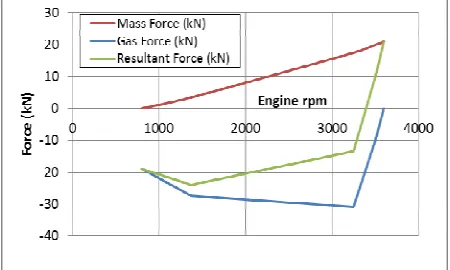
Fig. 4 Calculation of Gas, Inertia and Resultant Load
So, following 6 load cases for FEA are considered: • Load case #1: bolting pre load, contact definition,
clearances, over sizes.
• Load case #2: Mass forces (gas exchange T.D.C) at 1375 rpm.
• Load case #3: Mass forces (gas exchange T.D.C) at 3250 rpm (rated speed).
• Load case #4: Mass forces (gas exchange T.D.C) at 3600 rpm (over speed).
• Load case #5: Gas and mass forces (ignition T.D.C) at 1375 rpm.
• Load case #6: Gas and mass forces (ignition T.D.C) at 3250 rpm (rated speed).
• Load case combination 1 for HCF analysis at 1375 rpm: load cases #2 and #5
• Load case combination 2 for HCF analysis at 3250 rpm: load cases #3 and #6
3.3 Boundary Conditions.
• Applied material for connecting rod is C70S6. • A typical surface roughness is assumed 60µm. • The maximum bolt pretension is critical for HCF
behavior and the minimum pretension is critical for contact behavior. Maximum bolting pre load 50 KN and minimum bolting pre load 44 KN.
• Constant temperature close to the maximum oil temperature is assumed.
• All the contacts with the rotating between sliding parts are assumed small sliding.
• Modulus of Elasticity 21500 N/mm2 • Poisson’s Ratio 0.29
• Density 7.82 kg/cm3
With the above boundary conditions and appropriate material properties (linear or non-linear depending on the availability of the measurement data), the structural analysis is done for the steps and assuming a constant temperature. The stress-strain response provided by this analysis is used to predict high cycle fatigue (HCF).
Also, the absolute value of the tensile and compressive stress should not exceed the material yield strength even under the extreme load case of knocking or irregular firing.
Under this condition, it can cause a permanent deformation in the connecting rod in each cycle where the yield strength is exceeded causing its structural failure.
4.HIGH CYCLE FATIGUE
The following procedure is followed for evaluation of high cycle fatigue (HCF) behavior:
• The load cycles oscillating masses and oscillating masses in combination with gas pressure were calculated for engine speed at max. Torque and max. Power output.
• In each case from the two load cases the mean and alternating stresses were calculated by the FEM software.
[image:4.595.307.540.225.439.2]• Based on stresses and considering influence of e.g. stress gradient, surface roughness, etc., FEM software calculates two different safety factors against alternating stresses for every node of the FE-model:
Fig.4 Calculation of factor of safety
The resulting alternating load from the structural analysis is below the yield stress and therefore fracture requires many load cycles in the order of 106 or more. Areas typically critical with regard to HCF are connecting rod stem or those close to the transition radius. The most damaging combination of mean and alternating stress occurs when they are both tensile. The lower stress level is determined by the gas exchange cycle when inertia loads result in tensile stresses. For the upper stress level, the combination of inertia and gas pressure acts on the connecting rod.
The FEM software is used for the durability evaluation. In case of an elastic FEA where the linear but temperature dependent material properties are used, the stress conversion in the locations of local yielding is considered with the Neuber’s stress correction formula. To calculate the local material strength, influence factors such as surface roughness, stress gradient, mean stress, isothermal temperature and statistical factors are taken into account with respect to the FEM software.The safety factor at constant mean stress or constant stress ratio (R=σLower /σUpper) is calculated as the ratio of local component strength to local component stress and a target value of based on statistical data and experience is specified for product release.
challenge is to find a solution which is cost-effective, exploiting the material strength under predefined loading conditions. Hence, for such a complex shape, an automatic shape optimization is recommended.
5. RESULTS
During analysis, the following results have been obtained in form of calculation of factor of safety and maximum / mean stresses. It is necessary to ensure that minimum factor of safety is required to be 1.50. Wherever, its less, some structural change to the geometry of connecting rod is required so as to reduce the stresses and improve the factor of safety. Fig. 7 depicts HCF behavior at load case combination at 1374 rpm with mean stress constant. Fig.8 depicts HCF behavior at 3250 rpm with mean stress constant. Here, it needs attention to modify the geometry of connecting rod as at a particular point near big eye end, factor of safety has fallen below 1.5, thus indicating possible failure. Fig.9 depicts HCF behavior through alternate stresses and mean stresses at 3250 rpm.
Fig.6 HCF behavior at 1375 rpm (factor of safety)
Fig.7 HCF behavior at 3250 rpm (factor of safety)
Fig.8 HCF behavior at 3250 rpm (stresses)
5.CONCLUSIONS
The following conclusions are drawn from high cycle fatigue behavior of connecting rod:
• Mean and alternating stresses calculated for the connecting rod are on a moderate level.
• Resulting factors of safety are uncritical at shank of connecting rod. The required minimum factor of safety is 1.5. The occurring minimum is 1.71 at the connection between shank and big end.
• From the work carried out during this research it is concluded that complicated mechanisms can be simulated. The results obtained are logical and can be used to improve or modify the parts, shapes and performance of the whole system.
• In order to achieve results that are reliable when using the finite element method one has to use an acceptable element mesh with respect to the shape and size of the elements. As a help to produce an acceptable mesh there are quality criteria that must be fulfilled.
REFERENCES
[1] Kumar S K, Reddy T K and Hussain A S (2012), “Modeling and Analysis of TwoWheeler Connecting Rod”, I. J. Mer.,Vol. 2, No. 5, pp. 3367-3371.
[2] Pal S and Kumar S (2012), “Design Evaluation and Optimization of Connecting Rod Parameters Using FEM”, I. J. Emr., Vol 2, No. 6, pp. 21-25.
[3] Pathade C V, Patle B and Ingale N A (2012), “Stress Analysis of IC Engine Connecting Rod by FEM”, I. J. EIT.,Vol. 1, No. 3.
[4] Pathade C V, Patle B and Ingale N A (2012), “Stress Analysis of IC Engine Connecting Rod by FEM”, I. J. EIT.,Vol. 1, No. 3.
[5] Ramanpreet Singh,(2013) “Stress Analysis Of Orthotropic And isotropic Connecting Rod Using Finite element Method” International Journal of Mechanical Engineering and Robotics Research” Vol. 2, No. 2.
Engine by the Finite Elements Method”, Australian Journal of Basic and Applied Sciences.
[7] Ranjbarkohan M, Asadi R M and Dardashti N B (2011), “Stress Analysis of Connecting Rod of Nissan Z24 Engine by the Finite Elements Method”, Australian Journal of Basic and Applied Sciences.
[8] Shaari M S, Rahman M M, Noor M M, Kadirgama K and Amirruddin A K (2010), ”Design of Connecting Rod of Internal Combustion Engine: A Topology Optimization Approach”, pp. 155-156, NCMER, Faculty of Mechanical Engineering UMP Pekan, Kuantan,Pahang, Malaysia.
[9] Shaari M S, Rahman M M, Noor M M, Kadirgama K and Amirruddin A sK (2010), ”Design of Connecting Rod of Internal Combustion Engine: A Topology Optimization Approach”, pp. 155-156, NCMER, Faculty of Mechanical Engineering UMP Pekan, Kuantan,Pahang, Malaysia.
[10] Shao Zhong Jiang, Wen Bing Yan (2011),“Free Modal Analysis and Experimental Verification of a Diesel Engine’s Connecting Rod”, Advanced Materials Research, pp.314-316.
[11] Suraj Pal, Sunil Kumar (2012),“Design Evaluation and Optimization of Connecting Rod Parameters Using FEM”, Department of Mechanical Engg, Y.C.O. Engg. Talwandi sabo,,pp 21-25.
[12] Thomas G T, Srikari S and Suman J L M (2011), “Design of Connecting Rod for Heavy Duty Applications Produced by Different Processes for Enhanced Fatigue Life”, SASTECH Journal, Vol. 10, No. 1.
[13] Thomas G T, Srikari S and Suman J L M (2011), “Design of Connecting Rod for Heavy Duty Applications Produced by Different Processes for Enhanced Fatigue Life”, SASTECH Journal, Vol. 10, No. 1.
[14] Vatroslav (2004) Grubisic, “Fatigue Failure of Automobile components”, Fraunhofer Institute of reliability, Tokyo, pp. 01-37.
[15] Wenzhe Chen, Pinqiang Dai, Yonglu Chen, Qianting Wang and Zhengyi Jiang (2012,),“Design and Optimization on Connecting Rod Parts of Engineering Clamp Hanger Based on Metamodel”, Advanced Mechanical Design, pp.1845-1850.
[16] WUNan, LIAO Ri-dong, ZHANG Bao-cheng, ZUO Zheng-xing (2005),“Multi-Body System Dynamics Analysis of the Crank and Connecting Rod Mechanism in Diesel Engines”, School of Mechanical and Vehicular Engineering, Beijing Institute of Technology, (Chinese Internal Combustion Engine Engineering)