AT&T 585-310-203
AT&T Comcode: 106810849
Final
Issue 1
October, 1992
AUDIX
Voice Power
Release 3.0
Switch Integration to
AT&T System 75 and DEFINITY
Copyright1992 AT&T All Rights Reserved Printed in U.S.A.
Notice
While reasonable efforts were made to ensure that the information in this document was complete and accurate at the time of printing, AT&T can assume no responsibility for any errors. Changes and corrections to the information contained in this document may be incorporated into future reissues.
Your Responsibility for Your System’s Security
You are responsible for the security of your system. AT&T does not warrant that this product is immune from or will prevent unauthorized use of common-carrier telecommunication services or facilities accessed through or connected to it. AT&T will not be responsible for any charges that result from such unauthorized use. Product administration to prevent unauthorized use is your responsibility and your system administrator should read all documents provided with this product to fully understand the features available that may reduce your risk of incurring charges.
Federal Communications Commission (FCC) Statement
This equipment generates, uses, and can radiate radio-frequency energy and, if not installed and used in accordance with the instruction manual, may cause interference to radio communications. It has been tested and found to comply with the limits for a Class A computing device pursuant to Subpart J of Part 15 of FCC Rules, which are designed to provide reasonable protection against such interference when operated in a commercial environment.
Operation of this equipment in a residential area is likely to cause interference, in which case the user at his/her own expense will be required to take whatever measures may be required to correct the interference.
Trademarks
AUDIXand DEFINITYare registered trademarks of AT&T. Voice Poweris a trademark of AT&T.
INTELis a registered trademark of Intel Corporation.
Acknowledgment
Contents
________________________________________________________________________
________________________________________________________________________
________________________________________________________________________
About This Document
. . . . ixINTENDED AUDIENCES . . . . ix
PREREQUISITE SKILLS OR KNOWLEDGE . . . . x
DOCUMENT ORGANIZATION . . . . x
HOW TO USE THIS DOCUMENT . . . . xi
CONVENTIONS USED IN THIS DOCUMENT . . . . xi
TRADEMARKS AND SERVICE MARKS . . . . xii
RELATED RESOURCES . . . . xii
HOW TO MAKE COMMENTS ABOUT THIS DOCUMENT . . . . xii
1. Prerequisites
. . . . 1-1SAFETY CONSIDERATIONS . . . . 1-2
FACTORY ASSEMBLED SYSTEMS . . . . 1-2
AUDIX VOICE POWER R3.0 CONFIGURATION DIAGRAM . . . . 1-3
COMPONENT CHECKLISTS . . . . 1-4
2. Switch Integration Planning
. . . . 2-1ANALOG CHANNEL EXTENSIONS . . . . 2-2
DCP EXTENSION . . . . 2-3
COVERAGE PATH NUMBERS . . . . 2-3
TEST SUBSCRIBER EXTENSIONS . . . . 2-4
FEATURE ACCESS CODES . . . . 2-4
TRUNK LINE NAMES . . . . 2-5
iv Contents
________________________________________________________________________________________________ ________________________________________________________________________________________________ ________________________________________________________________________________________________
3. Hardware Installation
. . . . 3-1INSTALL THE DCP BOARD . . . . 3-2
REPLACING THE COVER . . . . 3-4
CONNECTING DIGITAL LINES TO THE DCP BOARD . . . . 3-4
4. Software Installation
. . . . 4-1INSTALL THE SWITCH INTEGRATION SOFTWARE . . . . 4-2
CHANGING THE SWITCH TYPE . . . . 4-4
5. AUDIX Voice Power R3.0 Switch Parameters
. . . . 5-1SET THE MESSAGE WAITING INDICATOR PARAMETERS . . . . 5-2
ADMINISTER THE SWITCH INTERFACE PACKAGE . . . . 5-5
SET THE SWITCH INTERFACE PARAMETERS . . . . 5-7
ASSOCIATE THE APPLICATION AND SWITCH INTERFACE . . . . 5-9
6. System 75 and DEFINITY G1 Administration
. . . . 6-1RELEASE R1V1 AND R1V2 SOFTWARE LIMITATIONS . . . . 6-2
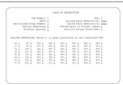
ASSIGN THE CLASS OF RESTRICTIONS . . . . 6-5
ADDING AND VERIFYING ANALOG CHANNELS . . . . 6-8
CONFIGURE THE DCP EXTENSION . . . . 6-11
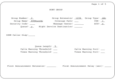
ADMINISTER THE HUNT GROUP (R1V1 AND R1V2) . . . . 6-14
7. DEFINITY G3 Switch Administration
. . . . 7-1ASSIGN THE CLASS OF RESTRICTIONS . . . . 7-2
ADDING AND VERIFYING ANALOG CHANNELS . . . . 7-6
Contents v
_ ______________________________________________________________________________________ _ ______________________________________________________________________________________ _ ______________________________________________________________________________________
8. Acceptance Tests
. . . . 8-1ADMINISTER THE CALL COVERAGE PATH . . . . 8-2
ADMINISTER THE TEST SUBSCRIBER STATIONS . . . . 8-4
REMOVING TEST SUBSCRIBERS FROM COVERAGE . . . . 8-8
9. Cut-to-Service Tasks
. . . . 9-1ADMINISTER THE CALL COVERAGE PATH . . . . 9-2
ADMINISTER THE SUBSCRIBERS . . . . 9-4
CUT-FROM-SERVICE . . . . 9-8
A. Troubleshooting
. . . . A-1PROBLEM LIST AND ACTION . . . . A-2
Abbreviations
. . . . AB-1Glossary
. . . . GL-1vi Contents
________________________________________________________________________________________________ ________________________________________________________________________________________________ ________________________________________________________________________________________________
LIST OF FIGURES
Figure 1-1. Connectivity Diagram for the System 75, DEFINITY G1, and G3
Switches . . . . 1-3
Figure 3-1. DCP Board ROM and RAM Jumper Location . . . . 3-2
Figure 3-2. Removing the Expansion Slot Cover . . . . 3-2
Figure 3-3. Inserting the DCP Board into a 6386/25 Expansion Slot . . . . 3-3
Figure 6-1. Class of Restriction screen . . . . 6-6
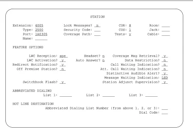
Figure 6-2. Analog channel assignment information on the Station screen . . . . . 6-9
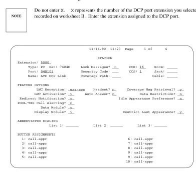
Figure 6-3. Page One of the Station screen for the DCP extension . . . . 6-11
Figure 6-4. Page three of the Station screen . . . . 6-12
Figure 6-5. Page four of the Station screen . . . . 6-13
Figure 6-6. Page One of the Hunt Group screen . . . . 6-15
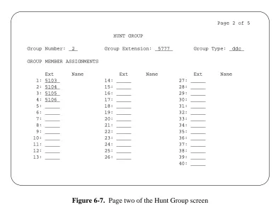
Figure 6-7. Page two of the Hunt Group screen . . . . 6-17
Figure 7-1. DEFINITY G3i and DEFINITY G3s Class of Restriction Screen . . . . . 7-3
Figure 7-2. Page One of the DEFINITY G3r Class of Restriction Screen . . . . 7-3
Figure 7-3. Page Two of the DEFINITY G3r Class of Restriction Screen . . . . 7-4
Figure 7-4. DEFINITY G3i and DEFINITY G3s Station Screen . . . . 7-7
Figure 7-5. DEFINITY G3r Station Screen . . . . 7-7
Figure 7-6. DEFINITY G3i and DEFINITY G3s DCP Station Screen . . . . 7-9
Figure 7-7. DEFINITY G3r DCP Station Screen . . . . 7-10
Figure 7-8. Page Two of the DEFINITY G3i or DEFINITY G3s Station
Screen . . . . 7-11
Figure 7-9. Page Two of the DEFINITY G3r Station Screen . . . . 7-11
Figure 7-10. Page Four of the DEFINITY G3i, G3r, and G3s Station Screen . . . . 7-12
Figure 7-11. Page Five of the DEFINITY G3i or DEFINITY G3s Station
Screen . . . . 7-13
Figure 7-12. Page Five of the DEFINITY G3r Station Screen . . . . 7-13
Figure 8-1. Coverage Path Screen . . . . 8-3
Figure 8-2. System 75 and DEFINITY G1 Station Screen . . . . 8-5
Figure 8-3. DEFINITY G3i and DEFINITY G3s Station Screen . . . . 8-6
Figure 8-4. DEFINITY G3r Station Screen . . . . 8-7
Contents vii
_ ______________________________________________________________________________________ _ ______________________________________________________________________________________ _ ______________________________________________________________________________________
Figure 9-2. System 75 and DEFINITY G1 Station Screen . . . . 9-5
Figure 9-3. DEFINITY G3i and DEFINITY G3s Station Screen . . . . 9-6
viii Contents
________________________________________________________________________________________________ ________________________________________________________________________________________________ ________________________________________________________________________________________________
LIST OF TABLES
Table 5-1. Switch Interface Parameter Values . . . . 5-7
Table 6-1. Analog Channel Station Screen Field Assignments . . . . 6-9
Table 6-2. LWC Reception Codes . . . . 6-12
About This Document
_ ______________________________________________________________________________________ _ ______________________________________________________________________________________ _ ______________________________________________________________________________________
AUDIXVoice PowerSwitch Integration to AT&T System 75, DEFINITYGeneric 1, and DEFINITY Generic 3 (585-310-203) contains installation and administration instructions for integrating a System 75, a DEFINITY Generic 1 (G1), a DEFINITY Generic 3i (G3i), a DEFINITY Generic 3r (G3r), and a
DEFINITY Generic 3s (G3s) switch with an AUDIXVoice Powersystem Release 3.0 (R3.0). In the document, the G3i, G3r, and G3s switches are referred to generically as G3. Any difference between the switches are explained in the text.
The document includes the following information:
•
Switch integration planning strategies•
Switch integration required hardware installation instructions•
Switch integration software installation instructions•
System 75, DEFINITY G1, and DEFINITY G3 administration instructions•
Acceptance test procedures•
Cut-to-Service procedures•
Troubleshooting guideThe document contains information only for the System 75, DEFINITY G1, and DEFINITY G3 integration with AUDIX Voice Power. If you have another type of switch, refer to the switch integration document for that switch.
INTENDED AUDIENCES
This document is designed primarily for the on-site AT&T services technician and customer technical personnel. Secondary audiences include the AT&T personnel shown in the following list.
•
field support•
the Technical Service Center (TSC)•
provisioning project managers•
the Sales and Technical Resource Center (STRC)•
helpline personnel•
factory assemble, load, and test (ALT) personnelx About This Document
________________________________________________________________________________________________ ________________________________________________________________________________________________ ________________________________________________________________________________________________
PREREQUISITE SKILLS OR KNOWLEDGE
Typical readers should understand AT&T computer systems, switches, and hardware and software
installation procedures. To effectively use the document, users of the document should complete an AT&T AUDIX Voice Power system installation training course.
DOCUMENT ORGANIZATION
•
Chapter 1, Prerequisites, explains the AUDIX Voice Power system R3.0 configuration and includes a component connectivity diagram that shows you each component in the configuration. The chapter also contains a hardware and software component checklist.•
Chapter 2, Switch Integration Planning, helps you plan, track, and record the switch integration. The chapter includes instructions for completing switch integration worksheets that you use throughout the document as you complete the integration.•
Chapter 3, Hardware Installation, describes the installation of the DCP board, cables to the switch, and cables to the AUDIX Voice Power system R3.0.•
Chapter 4, Software Installation, contains instructions for installing the AUDIX Voice Power system R3.0 software required to integrate the system with a System 75, DEFINITY G1, and DEFINITY G3 switch.•
Chapter 5, AUDIX Voice Power R3.0 Switch Parameters, contains instructions for administering an AUDIX Voice Power system R3.0 to integrate with the switch. The chapter includes instructions for setting the message waiting lamp parameters, setting the switch interface parameters, and associating the application and the switch interface.•
Chapter 6, System 75 and DEFINITY G1 Switch Administration, contains information and instructions for administering a System 75 and DEFINITY G1 switch to work with an AUDIX Voice Power system R3.0.•
Chapter 7, DEFINITY G3 Switch Administration, contains information and instructions for administering a DEFINITY G3i, a DEFINITY G3r, and a DEFINITY G3s switch to work with an AUDIX Voice Power system R3.0.•
Chapter 8, Acceptance Tests, provides instructions for the switch administration you must perform before you can continue with the acceptance tests.•
Chapter 9, Cut-to-Service, provides instructions for the switch administration you must perform before you can continue with cut-to-service.About This Document xi
_ ______________________________________________________________________________________ _ ______________________________________________________________________________________ _ ______________________________________________________________________________________
HOW TO USE THIS DOCUMENT
This document provides information you need to know when integrating a System 75, DEFINITY G1, or DEFINITY G3 switch with an AUDIX Voice Power system R3.0. Use this document along with the following documents:
•
6386/33 and 6386/25 Voice Processing Hardware Installation (585-310-111)•
AUDIX Voice Power System R3.0 Software Installation (585-310-115)•
AUDIX Voice Power System Upgrade Instructions (585-310-116)Do not perform any tasks in this document until you complete the required tasks in the installation or upgrade documents.
CONVENTIONS USED IN THIS DOCUMENT
The document uses the following typographic conventions.
•
Rounded boxes represent terminal keys that you must press.Example: Press ENTER shows you an instruction to press the enter, carriage return, or equivalent key.
•
Square boxes represent phone pad keys that you must press. Example: Press 0 shows you an instruction to press zero.•
The word enter means to type a value and press ENTERExample: Enteryto continue.
instructs you to typeyand press ENTER .
•
A rounded box that contains two or more words separated by hyphens represents two or three keys that you press at the same time. To use these keys, you hold down the first key while pressing the second key and, if appropriate, the third key.Example: Press ALT-d .
shows you an instruction to press and hold ALT while typing the letter d.
•
Typewriter-style constant-width type represents information you see displayed on your terminal screen, including screen displays, field names, prompts, and error messages. Constant-width bold typerepresents information you must enter from your keyboard.
Example: At theLogin ID?prompt, entersnowfox
•
Italic type represents variables that the system supplies or that you must supply. Example: Your filefilenameis formatted incorrectly.xii About This Document
________________________________________________________________________________________________ ________________________________________________________________________________________________ ________________________________________________________________________________________________
TRADEMARKS AND SERVICE MARKS
The document mentions the following trademarked products.
•
AUDIXis a registered trademark of AT&T.•
Voice Poweris a trademark of AT&T.•
DEFINITYCommunications System is a registered trademark of AT&T.•
INTELis a registered trademark of Intel Corporation.•
UNIXis a registered trademark of UNIX System Laboratories Inc.RELATED RESOURCES
In addition to this document, you may need to reference the following documents.
•
6386/33 and 6386/25 Voice Processing Hardware Installation (585-310-111)•
AUDIX Voice Power System R3.0 Software Installation (585-310-115)•
AUDIX Voice Power System Upgrade Instructions (585-310-116)•
AUDIX Voice Power System Release 3.0 Installation Checklist (585-310-112)•
AUDIX Voice Power System Release 3.0 Maintenance (585-310-113)•
AUDIX Voice Power System Release 3.0 Administration (585-310-532)•
AUDIX Voice Power System Release 3.0 Planning (585-310-602)HOW TO MAKE COMMENTS ABOUT THIS DOCUMENT
Behind the title page of this document you can find Reader Comment cards. While we have tried to make this document fit your needs, we need your suggestions for improving the document and urge you to complete and return the reader comment card.
If the reader comment cards have been removed from this document, please send your comments to the following address.
AT&T
Technical Publications Department Room 22-2C11
1. Prerequisites
_ ______________________________________________________________________________________ _ ______________________________________________________________________________________ _ ______________________________________________________________________________________
This chapter describes the requirements for the AT&T System 75, DEFINITY Generic 1 (G1), and a DEFINITY Generic 3 (G3) switch integration with an AUDIXVoice Powersystem Release 3.0 (R3.0). The chapter includes a diagram and checklists that show the configuration for the system. For more information on installing the AUDIX Voice Power system R3.0 hardware and software, refer to 6386/33 and 6386/25 Voice Processing Hardware Installation (585-310-111) and AUDIX Voice Power System Release 3.0 Software Installation (585-310-115).
Switch integration refers to the sharing of information between a voice mail system and a switch in order to provide a seamless interface to callers and subscribers. A fully integrated voice mail system answers each incoming phone call with information taken directly from the switch. To create an integrated environment for the AUDIX Voice Power system R3.0 and an AT&T System 75, a DEFINITY G1, or a DEFINITY G3, AT&T uses a Digital Communications Protocol (DCP) interface between the switch and the AUDIX Voice Power system. The DCP link transfers digital call information, such as called party and calling party information, to the AUDIX Voice Power system. Analog voice information is transferred through analog telephone lines connected to the switch and the AUDIX Voice Power system.
Before you connect the switch to the AUDIX Voice Power system, you must confirm that you have all required hardware and software integration components. Use the diagrams, checklists, and descriptions in this chapter to confirm that you have all required integration components.
1-2 Prerequisites
________________________________________________________________________________________________ ________________________________________________________________________________________________ ________________________________________________________________________________________________
SAFETY CONSIDERATIONS
CAUTION Electronic equipment can be damaged by electrostatic discharge. Do not touch any electronic
component unless you are properly grounded.
To prevent damage to the equipment and yourself, read and use the following precautions:
•
Familiarize yourself with the procedures necessary to prevent electrostatic damage to equipment.•
Shut off all power and remove all cables from equipment.•
Properly ground a work mat and wrist strap.•
Place the equipment on the work mat.•
Place the grounded wrist strap on your bare wrist. The wrist strap must contact your bare skin directly. Do not wear the wrist strap over your clothes.FACTORY ASSEMBLED SYSTEMS
If your customer ordered the complete hardware platform, an AT&T 6386 WGS with the AUDIX Voice Power R3.0 package, the AT&T factory ships the 6386 WGS to the site with most of the hardware and software assembled, loaded, and tested (ALT). The factory identifies ALT systems by placing an orange sticker over the door of the floppy disk drive. The sticker indicates that you do not need to reload the software.
Prerequisites 1-3
_ ______________________________________________________________________________________ _ ______________________________________________________________________________________ _ ______________________________________________________________________________________
AUDIX VOICE POWER R3.0 CONFIGURATION DIAGRAM
The AUDIX Voice Power system R3.0 connects to the System 75, DEFINITY G1, and DEFINITY G3 switches through the DCP link. Figure 1-1 shows you the connection between the AUDIX Voice Power system and the switch. Use the connectivity diagram to understand how the system components connect. Each item in the connectivity diagram is identified in the component checklists on the following pages. Use the component checklists to make sure you have all required components.
6386 PC AUDIX VOICE POWER
PRINTER DIGITAL PORT
SYSTEM 75, DEFINITY G1, DEFINITY G3i, DEFINITY G3r,
OR DEFINITY G3s
ANALOG PORTS
PARALLEL PORT COM 1 (RS232)
WIRE
FEMALE CONNECTIVITY
MALE CONNECTIVITY =
=
=
MODEM CABLE
IVP4 CARD(s) (4 PORTS) 103A
884A
HOUSE 8-WIRE
MODULAR
DCP CARD
VDC
103A
MODEM
PRINTER CABLE WIRE
103A
1-4 Prerequisites
________________________________________________________________________________________________ ________________________________________________________________________________________________ ________________________________________________________________________________________________
COMPONENT CHECKLISTS
The following checklists identify the components required for the AUDIX Voice Power system R3.0 integration with a System 75, DEFINITY G1, or DEFINITY G3 switch. Compare the components that you have on site with the checklists to make sure you have everything required for the installation. The
checklists contain each AUDIX Voice Power system component and list a Price Element Code (PEC) for each component. You can use the PECs to order systems, upgrades, and additions. Some PEC descriptions include comcodes or J-drawing numbers used by AT&T Services personnel when required. For a complete list of PECs, refer to AUDIX Voice Power System Release 3.0 Planning (585-310-602).
AUDIX Voice Power Release 3.0 Base Operating System Software
_ ______________________________________________________________________________________
PEC Comcode/J-Drawing Description
_ ______________________________________________________________________________________ _ ______________________________________________________________________________________
6950-BD1 UNIX 3.2.2
_ ______________________________________________________________________________________
AUDIX Voice Power Release 3.0 Hardware
_ ______________________________________________________________________________________
PEC Comcode/J-Drawing Description
_ ______________________________________________________________________________________ _ ______________________________________________________________________________________
6950-DB1 6386/25 without disk
_ ______________________________________________________________________________________
6950-DC1 6386/33 with 300MB disk
_ ______________________________________________________________________________________
69595 300MB disk
_ ______________________________________________________________________________________
69581 2MB RAM SIM Modules
_ ______________________________________________________________________________________
8302-101 DCP card for System 75, DEFINITY G1, and DEFINITY G3
_ ______________________________________________________________________________________
8304-IV4 4 port card
_ ______________________________________________________________________________________
69587 VDC600 card
_ ______________________________________________________________________________________
AUDIX Voice Power Release 3.0 Peripherals
_ ______________________________________________________________________________________
PEC Comcode/J-Drawing Description
_ ______________________________________________________________________________________ _ ______________________________________________________________________________________
69579 Monochrome Monitor
_ ______________________________________________________________________________________
69586 Color Monitor
_ ______________________________________________________________________________________
6951-417 NCR parallel printer
_ ______________________________________________________________________________________
6950-EB1 Printer cable
_ ______________________________________________________________________________________
63183 Hayes Smartmodem OPTIMA 2400
_ ______________________________________________________________________________________
2721-28E Modem cable
Prerequisites 1-5
_ ______________________________________________________________________________________ _ ______________________________________________________________________________________ _ ______________________________________________________________________________________
AUDIX Voice Power Release 3.0 Kits
_ ______________________________________________________________________________________
PEC Comcode/J-Drawing Description
_ ______________________________________________________________________________________ _ ______________________________________________________________________________________
1228-300 AUDIXVoice PowerR3.0 Application Kit J1P287TB-1 List 2 IVPSS R3.0 Software
J1P287TB-1 List 1 AUDIXVoice Power(tm R3.0 Application Software J1P287TB-1 List 3 AUDIXVoice Power(tm R3.0 Speech Software
106810880 6386/33 and 6386/25 Voice Processing Hardware Installation 106856503 AUDIXVoice PowerSystem R3.0 Software Installation 106810898 AUDIXVoice PowerSystem R3.0 Installer’s Checklist 106841513 AUDIXVoice PowerSystem R3.0 Maintenance 601306004 IVP4 Circuit pack, cords, manual
106435878 AUDIXVoice PowerVideo and Workbook
_ ______________________________________________________________________________________
1228-302 AUDIXVoice PowerUpgrade R2.1.1/R3.0 J1P287TB-1 List 2 IVPSS R3.0 Software
J1P287TB-1 List 1 AUDIXVoice Power(tm R3.0 Application Software J1P287TB-1 List 3 AUDIXVoice Power(tm R3.0 Speech Software
J1P287TB-1 List 15 AUDIXVoice Power(tm R2.1.1 to R3.0 Upgrade Software 106810880 6386/33 and 6386/25 Voice Processing Hardware Installation 106856503 AUDIXVoice PowerSystem R3.0 Software Installation 106810898 AUDIXVoice PowerSystem R3.0 Installer’s Checklist 106841513 AUDIXVoice PowerSystem R3.0 Maintenance 406014951 300MB disk drive
_ ______________________________________________________________________________________
1228-303 AUDIXVoice PowerUpgrade R2.0/R3.0 with System 75/G1/G3 J1P287TB-1 List 2 IVPSS R3.0 Software
J1P287TB-1 List 1 AUDIXVoice Power(tm R3.0 Application Software J1P287TB-1 List 3 AUDIXVoice Power(tm R3.0 Speech Software
J1P287TB-1 List 5 AUDIXVoice Power(tm R2.0 to R3.0 Upgrade Software 106810880 6386/33 and 6386/25 Voice Processing Hardware Installation 106856503 AUDIXVoice PowerSystem R3.0 Software Installation 106810898 AUDIXVoice PowerSystem R3.0 Installer’s Checklist 106841513 AUDIXVoice PowerSystem R3.0 Maintenance 406014951 300MB disk drive
_ ______________________________________________________________________________________
1228-304 AUDIXVoice PowerR3.0 Switch Integration for System 75/G1/G3
J1P287TB-1 List 7 System 75/G1/G3 Switch Integration Software
106810849 AUDIXVoice PowerSystem R3.0 Switch Integration to System 75, DEFINITY G1 and DEFINITY G3
_ ______________________________________________________________________________________
1-6 Prerequisites
________________________________________________________________________________________________ ________________________________________________________________________________________________ ________________________________________________________________________________________________
AUDIX Voice Power Release 3.0 Kits (continued)
_ ______________________________________________________________________________________
PEC Comcode/J-Drawing Description
_ ______________________________________________________________________________________ _ ______________________________________________________________________________________
1228-306 AUDIXVoice PowerUpgrade R2.1.1/R3.0 J1P287TB-1 List 2 IVPSS R3.0 Software
J1P287TB-1 List 1 AUDIXVoice Power(tm R3.0 Application Software J1P287TB-1 List 3 AUDIXVoice Power(tm R3.0 Speech Software
J1P287TB-1 List 15 AUDIXVoice Power(tm R2.1.1 to R3.0 Upgrade Software 106810880 6386/33 and 6386/25 Voice Processing Hardware Installation 106856503 AUDIXVoice PowerSystem R3.0 Software Installation 106810898 AUDIXVoice PowerSystem R3.0 Installer’s Checklist
_ ______________________________________________________________________________________
1228-307 AUDIXVoice PowerUpgrade R2.0/R3.0 J1P287TB-1 List 2 IVPSS R3.0 Software
J1P287TB-1 List 1 AUDIXVoice Power(tm R3.0 Application Software J1P287TB-1 List 3 AUDIXVoice Power(tm R3.0 Speech Software
J1P287TB-1 List 5 AUDIXVoice Power(tm R2.0 to R3.0 Upgrade Software 106810880 6386/33 and 6386/25 Voice Processing Hardware Installation 106856503 AUDIXVoice PowerSystem R3.0 Software Installation 106810898 AUDIXVoice PowerSystem R3.0 Installer’s Checklist 106841513 AUDIXVoice PowerSystem R3.0 Maintenance
_ ______________________________________________________________________________________
AUDIX Voice Power Release 3.0 Documentation
_ ______________________________________________________________________________________
Select Code PEC Comcode Description
_ ______________________________________________________________________________________ _ ______________________________________________________________________________________
585-310-202 106810856 AUDIXVoice PowerSystem R3.0 System and Feature Description 585-310-013 106810864 AUDIXVoice PowerSystem R3.0 Documentation Guide
_ ______________________________________________________________________________________
585-310-602 106810872 AUDIXVoice PowerSystem R3.0 Installation Planning 585-310-111 106810880 6386/33 and 6386/25 Voice Processing Hardware Installation 585-310-115 106856503 AUDIXVoice PowerSystem R3.0 Software Installation 585-310-116 106857840 AUDIXVoice PowerSystem Upgrade Instructions 585-310-112 106810898 AUDIXVoice PowerSystem R3.0 Installer’s Checklist 585-310-113 106841513 AUDIXVoice PowerSystem R3.0 Maintenance
_ ______________________________________________________________________________________
585-310-532 106810922 AUDIXVoice PowerSystem R3.0 Administration 585-310-711 106810930 AUDIXVoice PowerSystem R3.0 Portable User’s Guide 585-310-712 106810948 AUDIXVoice PowerSystem R3.0 Quick Reference 585-310-713 106810955 AUDIXVoice PowerSystem R3.0 Artwork Package 585-310-714 106810963 AUDIXVoice PowerSystem R3.0 Wallet Card
585-310-715 106810971 AUDIXVoice PowerSystem R3.0 Business Card Sticker
_ ______________________________________________________________________________________
585-310-203 70716 106810849 AUDIXVoice PowerSystem R3.0 Switch Integration to System 75, DEFINITYG1, and DEFINITYG3
Prerequisites 1-7
_ ______________________________________________________________________________________ _ ______________________________________________________________________________________ _ ______________________________________________________________________________________
Documentation Advance Shipment Kit
_ ______________________________________________________________________________________
PEC Comcode Description
_ ______________________________________________________________________________________ _ ______________________________________________________________________________________
70700 Documentation Advance Shipment Kit
106810856 AUDIXVoice PowerSystem R3.0 System and Feature Description 106810864 AUDIXVoice PowerSystem R3.0 Documentation Guide
106810872 AUDIXVoice PowerSystem R3.0 Installation Planning 106810922 AUDIXVoice PowerSystem R3.0 Administration 106810930 AUDIXVoice PowerSystem R3.0 Portable User’s Guide 106810948 AUDIXVoice PowerSystem R3.0 Quick Reference 106810955 AUDIXVoice PowerSystem R3.0 Artwork Package 106810963 AUDIXVoice PowerSystem R3.0 Wallet Card
106810971 AUDIXVoice PowerSystem R3.0 Business Card Sticker
1-8 Prerequisites
2. Switch Integration Planning
_ ______________________________________________________________________________________ _ ______________________________________________________________________________________ _ ______________________________________________________________________________________
Before you implement the System 75, DEFINITY G1, or DEFINITY G3 switch integration with an AUDIX Voice Power system R3.0, you must plan the process. This chapter provides worksheets and information to help you plan and record the integration. You use the worksheets later to complete the switch integration process. The planning and worksheets in this chapter must be completed by the customer before the AUDIX Voice Power system R3.0 installation.
Some of the information in this chapter may have been collected during the completion of AUDIX Voice Power System Release 3.0 Planning (585-310-602). You may be referred to the planning document to verify that you have collected the information or to copy information. By completing the worksheets you collect the following information:
•
analog channel extensions•
DCP extension•
acceptance test coverage path number•
cut-to-service coverage path number•
test subscriber extensions•
code to light message waiting lamps•
code to extinguish message waiting lampsContinue with the instructions on the next page to plan the switch integration.
2-2 Switch Integration Planning
________________________________________________________________________________________________ ________________________________________________________________________________________________ ________________________________________________________________________________________________
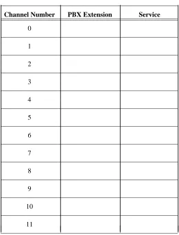
ANALOG CHANNEL EXTENSIONS
The AUDIX Voice Power system R3.0 receives speech from the switch over analog voice channels. Each channel has an assigned service on the AUDIX Voice Power system. For example, if a subscriber calls the AUDIX Voice Power number and accesses voice mail, the subscriber dialed an extension for a channel connected to the voice mail service.
During the switch administration process, you must administer the extensions assigned to the channels. In Appendix A of AUDIX Voice Power System Release 3.0 Planning (585-310-602), you completed a PBX worksheet. The PBX worksheet had you identify the channel extensions and record the extensions on Table A-3. You must use the information you recorded on the table as you complete the switch
administration procedures in this document. Worksheet A duplicates Table A-3 in the planning document. Copy the information from the planning document onto worksheet A to avoid referencing two documents during the switch administration procedures.
Worksheet A: Channels/PBX Extensions/Services
_ ___________________________________________________
Channel Number PBX Extension Service
Switch Integration Planning 2-3
_ ______________________________________________________________________________________ _ ______________________________________________________________________________________ _ ______________________________________________________________________________________
DCP EXTENSION
The AUDIX Voice Power system R3.0 communicates with the switch through the DCP link. During the switch administration process, you must set up a digital station for the DCP link. To set up the link, you must select an extension for the DCP station. Select an extension currently unassigned on the switch that fits into the dial plan. Do not use the extension for a subscriber station. To view a list of assigned stations use thelist stationcommand on the switch. Once you determine the extension you want to use for the DCP station, record the extension on line 1 of worksheet B, Switch Integration Information.
Worksheet B: Switch Integration Information
_
____________________________________________________________
Line # Information Type Value
_
____________________________________________________________ _
____________________________________________________________
1. DCP extension:
_
____________________________________________________________
2. Acceptance Test coverage path number
_
____________________________________________________________
3. Cut-to-service coverage path number
_
____________________________________________________________
4. Test subscriber 1 extension: __________ Test subscriber 1 name:
_
____________________________________________________________
5. Test subscriber 2 extension: __________ Test subscriber 2 name:
_
____________________________________________________________
6. Code to Light:
(Leave Word Calling Send a Message)
_
____________________________________________________________
7. Code to Extinguish:
(Leave Word Calling Cancel a Message)
_ ____________________________________________________________
COVERAGE PATH NUMBERS
When a subscriber dials the AUDIX Voice Power phone number and calls the system, the switch needs to know where to send the call. You use a coverage path to instruct the switch where to "cover" or send the call. For the AUDIX Voice Power system, the coverage path sends the call over the DCP link. To establish the coverage path, you must select a coverage path number for acceptance tests and a coverage path number for the cut-to-service process.
2-4 Switch Integration Planning
________________________________________________________________________________________________ ________________________________________________________________________________________________ ________________________________________________________________________________________________
The cut-to-service process provides AUDIX Voice Power service to all subscribers. To cut subscribers into service, you change the coverage path for each AUDIX Voice Power subscriber. When you select a coverage path for the cut-to-service process, look at the coverage path assigned to the subscribers that will have AUDIX Voice Power service. Select the coverage path number assigned to the majority of the subscribers. By using the existing coverage path, you do not have to change each subscriber station. Instead, you change the existing coverage path by setting the first coverage point to the DCP extension. For example, if you have 100 subscribers identified to receive AUDIX Voice Power service and 75 of the subscribers have1assigned as the coverage path, use1as the AUDIX Voice Power coverage path. Once you determine the cut-to-service coverage path number, write the number on line 3 of worksheet B, Switch Integration Information.
TEST SUBSCRIBER EXTENSIONS
To perform the acceptance test procedures, you must administer two test subscribers on the switch. In Appendix A of AUDIX Voice Power System Release 3.0 Planning (585-310-602), you completed a PBX worksheet. The PBX worksheet had you identify two test subscriber names and extensions and record the information on Table A-4. You must use the information you recorded on the table as you complete the switch administration procedures in this document. You can copy the information from the planning document onto worksheet B to avoid referencing two documents during the switch administration procedures. Record the test subscriber names and extensions on lines 4 and 5 of worksheet B, Switch Integration Information.
FEATURE ACCESS CODES
For the AUDIX Voice Power system to operate message waiting lamps properly, you need to determine the Feature Access Codes (FAC) used on the switch to light and extinguish the message waiting lamps. You need to find the the codes for the following two parameters:
•
Leave Word Calling Send a Message - The AUDIX Voice Power system R3.0 uses this value for the Code to Light parameter.•
Leave Word Calling Cancel a Message - The AUDIX Voice Power system R3.0 uses this value for the Code to extinguish parameter.To find the values assigned for the two FAC, use thedisplay feature-access-codeson the switch. You may need to use the PAGE or NEXT PAGE key to find the codes. Once you find the Code to
Switch Integration Planning 2-5
_ ______________________________________________________________________________________ _ ______________________________________________________________________________________ _ ______________________________________________________________________________________
TRUNK LINE NAMES
A trunk line is a telephone communication path or channel between two points, one of the paths usually being the local telephone company central office or switching center. You can use a trunk line to provide subscribers with access to the AUDIX Voice Power system from outside your location. If you use a trunk line for AUDIX Voice Power system outside access, administer the trunk to have the same extension as the inside system number. For example, if subscribers dial extension1212from their desks to access the AUDIX Voice Power system, the outside trunk should have the same last four digits, such as555-1212.
Each trunk is administered at theTRUNK ADMINISTRATIONscreen on the System 75, DEFINITY G1, or
DEFINITY G3 switch and has a name that identifies the trunk. The AUDIX Voice Power system accepts trunk names from the switch that are at least 34 characters in length. If the system receives a trunk name less than 34 characters, the system generates an error. You can administer the AUDIX Voice Power system to accept specific trunk names less than 34 character. Certain conditions can occur for which you need to administer a less than 34 character trunk name, such as those shown in the following list.
•
Administer the name of any trunk that terminates at an attendant console. This allows attendants to transfer callers directly to the voice mail system.•
Administer the trunk namesConferenceandConference 2, used for a two party conference call when the two party call attempts to call a third party.To set up the AUDIX Voice Power system R3.0 outside access trunk, contact your local phone company. After the phone company sets up the trunk line, administer the trunk on your switch. Name the trunk OUTSIDE CALLand terminate the trunk at the DCP extension, listed on worksheet B. Record the AUDIX Voice Power system trunk number and name on worksheet C, Trunk Line Administration. Record the trunk names and numbers of any less than 34 character trunk on worksheet C. In Chapter 5, AUDIX Voice Power R3.0 Switch Parameters, you administer the trunk names on the AUDIX Voice Power system.
NOTE
2-6 Switch Integration Planning
________________________________________________________________________________________________ ________________________________________________________________________________________________ ________________________________________________________________________________________________
Worksheet C: Trunk Line Administration
_ ______________________________________________________________________________________
Trunk Number Trunk Name Description and Purpose
3. Hardware Installation
_ ______________________________________________________________________________________ _ ______________________________________________________________________________________ _ ______________________________________________________________________________________
This chapter contains instructions for installing AUDIX Voice Power system R3.0 hardware required to integrate with a System 75, DEFINITY G1, or DEFINITY G3 switch. Before you perform the tasks in this chapter, complete the required tasks in 6386/33 and 6386/25 Voice Processing Hardware Installation (585-310-111). Do not perform any tasks in this chapter until you complete the instructions in the installation document. This chapter only contains hardware installation instructions for hardware required to connect the AUDIX Voice Power system to the switch. Refer to the installation document for
instructions on other AUDIX Voice Power system components.
As you install the switch integration hardware, you must complete the following tasks.
•
Install the DCP board•
Replace the cover•
Connect the digital lines to the DCP boardNOTE
The instructions in this chapter include the installation of the Digital Communications Protocol (DCP) board. Other AT&T documents may refer to the board as the PC/PBX Expansion board. Both names refer to the same board.
Continue with the instructions on the next page to install the hardware.
3-2 Hardware Installation
________________________________________________________________________________________________ ________________________________________________________________________________________________ ________________________________________________________________________________________________
INSTALL THE DCP BOARD
The Digital Communications Protocol (DCP) board provides a communication link between the AUDIX Voice Power system and the switch. You must install the board in the AUDIX Voice Power computer. Use the following procedures to install the board.
1. Check the ROM and RAM jumpers on the DCP board. The jumpers should match the diagram shown in Figure 3-1.
LINE
OTHER R
O M
R A M
PHONE
Figure 3-1. DCP Board ROM and RAM Jumper Location
2. Select a 16 or 32 bit slot for the installation of the DCP board. On a desktop model, use a slot as far to the left as possible. On a floor model, use a slot as for to the rear as possible.
3. Remove the screw from the metal cover of the expansion slot you selected. Do not discard the screw. You must use the screw to secure the DCP board.
4. Lift out the metal cover as shown in Figure 3-2.
Hardware Installation 3-3
_ ______________________________________________________________________________________ _ ______________________________________________________________________________________ _ ______________________________________________________________________________________
5. Hold the DCP board by the edges and insert the board into the slot as shown in Figure 3-3.
Check that the DCP board bracket is at the back of the chassis (top of the chassis for floor models) and fits into the space left by the slot cover. Align the connector edge of the board with the socket on the adapter board. The front edge of the board fits in the alignment guide attached near the front (bottom on floor models) of the WGS enclosure.
Figure 3-3. Inserting the DCP Board into a 6386/25 Expansion Slot
6. When you properly seat the DCP board in the expansion slot, press down evenly on the board edges to ensure a solid connection.
7. Secure the DCP board in the chassis by using the expansion slot cover screw.
3-4 Hardware Installation
________________________________________________________________________________________________ ________________________________________________________________________________________________ ________________________________________________________________________________________________
REPLACING THE COVER
You must replace the cover on the AUDIX Voice Power computer. Refer to Appendix A, Removing/Replacing the Computer Cover, in 6386/33 and 6386/25 Voice Processing Hardware Installation (585-310-111) for instructions.
Once you have replaced the cover on the computer, continue with the next section, Connecting Digital Lines to the DCP Board.
CONNECTING DIGITAL LINES TO THE DCP BOARD
After you install the DCP board and replace the cover on the computer, you must connect the DCP board to the switch. The instructions in this section describes how to cable the data lines from the DCP board to a connect block. You must also install wiring from the connect block to the appropriate digital port on a System 75, DEFINITY G1, or DEFINITY G3 switch.
1. Connect one end of the digital phone line to the LINE jack on the DCP board.
2. Insert the free end of the line into a connect block.
3. Insert a digital line in the open end of the connect block.
4. Connect the free end of the digital line directly to a digital port on the System 75, DEFINITY G1, or DEFINITY G3 switch.
5. Once you connect the digital line to the switch, write the digital port number on the following line. You use the port number during the switch administration process.
_ ___________
Port Number: __________ ___________
4. Software Installation
_ ______________________________________________________________________________________ _ ______________________________________________________________________________________ _ ______________________________________________________________________________________
The AUDIX Voice Power Switch Integration Software for AT&T System 75 or DEFINITY G1, or
DEFINITY G3 PBX contains the driver for the DCP board and all software required to integrate the AUDIX Voice Power system R3.0 with a System 75, DEFINITY G1, or DEFINITY G3 switch. The software should be installed only by AT&T authorized and trained personnel or by the system administrator.
Do not install the software until you complete the PBX Worksheet in Appendix A, Planning Worksheets, of AUDIX Voice Power System Release 3.0 Planning (585-310-602). You use the information on the
worksheet as you install the switch integration software. Before you install the switch integration software, install all AUDIX Voice Power software as instructed in AUDIX Voice Power System Release 3.0 Software Installation (585-310-115). When you have completed the planning process, continue with the instructions on the next page.
4-2 Software Installation
________________________________________________________________________________________________ ________________________________________________________________________________________________ ________________________________________________________________________________________________
INSTALL THE SWITCH INTEGRATION SOFTWARE
1. Enterrootat theConsole Loginprompt to log in as the AUDIX Voice Power administrator. The system responds with thePasswordprompt.
2. Press ENTER .
3. The system responds with the UNIX system prompt (#). 4. Enterinstallpkgat the UNIX system prompt (#).
The system responds with the following prompt:
Confirm
Please insert the floppy disk.
If the program installation requires more than one floppy disk, be sure to insert the disks in the proper order, starting with disk number 1.
After the first floppy disk, instructions will be provided for inserting the remaining floppy disks.
Strike ENTER when ready or ESC to stop.
5. Insert the AUDIX Voice Power Switch Integration Software for AT&T System 75 or DEFINITY G1 or G3 PBX diskette in the floppy drive and press ENTER .
After a series of informational messages, the system responds with the following prompt:
Choose the release number of the switch to which this package is to interface:
1. R1V1 2. R1V2 3. R1V3
4. R1V4 (or Definity G1) 5. R1V5 (or Definity G3)
Enter your choice (1,2,3,4,5 or h for help):
6. Find the version of the switch you have and enter the number shown beside the version. Refer to the PBX Worksheet in Appendix A, Planning Worksheets, of AUDIX Voice Power System Release 3.0 Planning (585-310-602) to find the version of the switch.
Depending on the switch type you select, you see a message confirming your selection and providing further instructions. For example, if you select version R1V5, you see the following message on the screen:
You have selected System 75 software version R1V5. Be sure you have the updated version of this software to avoid problems with your multi-appearance stations.
Software Installation 4-3
_ ______________________________________________________________________________________ _ ______________________________________________________________________________________ _ ______________________________________________________________________________________
7. The system begins to rebuild the UNIX operating system and displays the following messages on the screen:
Switch Package associated with AUDIX Voice Power 3.0
The UNIX Operating System will now be rebuilt.
This will take approximately 2 minutes. Please wait.
The UNIX kernel has been rebuilt.
You may now remove the floppy disk.
Confirm
To complete the install/remove process a shutdown is now being initiated automatically.
Make sure your floppy drive is empty. If you are
installing or removing controller boards, you may power down the system after the shut down is completed.
Strike ENTER when ready or ESC to stop.
8. Remove the diskette from the floppy disk drive.
9. Press ENTER to begin the system shutdown.
The system responds with several informational messages. At the end of the shutdown process, the system displays following prompt:
The system is down. Reboot the system now.
10. Press Ctrl-Alt-Del simultaneously or press the reset button to reboot the system.
When the system completes the reboot, the system returns you to theConsole Loginprompt.
4-4 Software Installation
________________________________________________________________________________________________ ________________________________________________________________________________________________ ________________________________________________________________________________________________
CHANGING THE SWITCH TYPE
If you have an ALT system, the switch type was set at the factory. If the switch type is not correct, you can change the setting by using the/dcp/bin/switchutility. You also may have to change the setting after installing a software update on the switch. Do not change the switch type unless the switch type is incorrect. Use the instructions in this section to change the switch type.
1. Enterrootat theConsole Loginprompt to log in as the AUDIX Voice Power administrator. The system responds with thePasswordprompt.
2. Press ENTER .
3. The system responds with the UNIX system prompt (#). 4. Enter/dcp/bin/switchat the UNIX system prompt (#).
The system responds with the following prompt:
Choose the release number of the switch to which this package is to interface:
1. R1V1 2. R1V2 3. R1V3
4. R1V4 (or Definity G1) 5. R1V5 (or Definity G3)
Selection (1-5) [press <Enter> for <current switch type> or h for help]:
The message tells you the type of switch currently assigned to the system. In the example message above, the switch type would appear in the<current switch type>field.
5. Enter the number shown beside the appropriate switch version.
Depending on the switch type you select, you see a message confirming your selection and providing further instructions. For example, if you select version R1V5, you see the following message on the screen:
You have selected System 75 software version R1V5 (or Definity G1). Be sure you have the updated version of this software to avoid problems with your multi-appearance stations.
Read the message and proceed to the next step.
6. Depending on the switch type selected, the system may stop. If the system stops, you see a message on the screen indicating that the system has stopped. Start the system.
5. AUDIX Voice Power R3.0 Switch Parameters
_ ______________________________________________________________________________________ _ ______________________________________________________________________________________ _ ______________________________________________________________________________________
This chapter contains administration information for integrating an AUDIX Voice Power system R3.0 with the System 75, DEFINITY G1, or DEFINITY G3 switch. The AUDIX Voice Power system needs to know specific information about the switch, for example whether to activate message waiting lamps and the type and length of the disconnect. This chapter includes instructions for the following procedures:
•
setting the message waiting lamp parameters•
administering the switch interface package and trunks•
setting the switch interface parameters•
associating the application and the switch interfaceContinue with the procedures on the next page to integrate an AUDIX Voice Power system R3.0 with the switch.
5-2 AUDIX Voice Power R3.0 Switch Parameters
________________________________________________________________________________________________ ________________________________________________________________________________________________ ________________________________________________________________________________________________
SET THE MESSAGE WAITING INDICATOR PARAMETERS
You need to instruct the AUDIX Voice Power system R3.0 if you want to activate the message waiting indicator option. If you plan to activate the message waiting indicator feature, you need to determine if you want the system to "refresh" or make sure the message waiting indicators are in the correct state. To use the refresh feature, you must set a time interval for the AUDIX Voice Power system to perform the sequential refresh process. Use the instructions in this section to set the message waiting indicator parameters.
1. Enteraudixat theConsole Loginprompt. 2. Enter your password at thePasswordprompt.
After you enter the password, you see theIVPSS 3.0menu as shown in the following example.
IVPSS R3.0
AT&T FACE
Voice System Administration Exit
3. Select theVoice System Administrationoption from the menu.
After you select the option, you see theVOICE SYSTEM ADMINISTRATIONmenu as shown in the following
example.
Voice System Administration
Application Package Administration Configuration Management
Reports
Switch Interfaces System Monitor
4. Select theSwitch Interfacesoption from the menu.
After you select the option, you see theSWITCH INTERFACESmenu as shown in the following example.
Switch Interface
AUDIX Voice Power R3.0 Switch Parameters 5-3
_ ______________________________________________________________________________________ _ ______________________________________________________________________________________ _ ______________________________________________________________________________________
5. Select theData Interfacesoption from the menu.
After you select the option, you see theDATA INTERFACESmenu as shown in the following example.
Data Interfaces
>Application/Switch Interface Association Message Waiting Lamp Parameters
Switch Interface Package Administration
6. Select theMessage Waiting Lamp Parametersoption from theDATA INTERFACESmenu.
After you select the option, you see theMESSAGE WAITING LAMP PARAMETERSform as shown in the
following example.
Message Waiting Lamp Parameters
Allow Message Waiting Lamp Control? _ Y_ E_ S_ Allow Refresh? _ Y_ E_ S_ Refresh Interval: _ 9_ 0_
Code to Light: _______ Code to Extinguish: _______
7. EnterYfor yes orNfor no in theAllow Message Waiting Lamp Controlfield.
The field allows you to turn the message waiting lamp option on or off. If you enterNO, the system does not update message waiting lamps. If you enterYES, the system updates message waiting lamps.
8. EnterYfor yes orNfor no in theAllow Refreshfield.
By turning the feature on, AUDIX Voice Power "refreshes" or makes sure the message waiting lamps are in the correct state. Different types of telephones use different methods of turning message waiting lamps off and on. Refresh turns the lamp on again to make sure the lamp is in the correct state.
9. Enter a time, in seconds, in theRefresh Intervalfield.
5-4 AUDIX Voice Power R3.0 Switch Parameters
________________________________________________________________________________________________ ________________________________________________________________________________________________ ________________________________________________________________________________________________
10. Enter the code for lighting the MWL in theCode to Lightfield.
The code is specific to the switch integrated with the AUDIX Voice Power system. Worksheet B in Chapter 2, Switch Integration Planning, provides instructions for determining the code. Refer to worksheet B to locate the code.
11. Enter the code for turning off the MWL in theCode to Extinguishfield.
The code is specific to the switch integrated with the AUDIX Voice Power system. Worksheet B in Chapter 2, Switch Integration Planning, provides instructions for determining the code. Refer to worksheet B to locate the code.
12. When you finish entering the information, press SAVE to enter the information into the system.
After you press the key, you see a confirmation window as shown in the following example.
Information
Message waiting lamp parameters saved. Press any key to continue.
13. Press ENTER to exit the window and return to theDATA INTERFACESmenu.
AUDIX Voice Power R3.0 Switch Parameters 5-5
_ ______________________________________________________________________________________ _ ______________________________________________________________________________________ _ ______________________________________________________________________________________
ADMINISTER THE SWITCH INTERFACE PACKAGE
The AUDIX Voice Power system R3.0 needs to know the type of switch integration package used to connect with the switch. For a System 75, DEFINITY G1, or DEFINITY G3 system, you use the AT&T System 75 or DEFINITY G1/G3 Switch Integration package. After you specify the type of switch package, you must identify any trunk lines connected to the AUDIX Voice Power system. Use the following procedure to administer the switch integration package and identify the trunk lines.
1. Select theSwitch Interface Package Administrationoption from theDATA INTERFACES
menu.
After you select the option, you see theSWITCH INTERFACE PACKAGE ADMINISTRATIONmenu as shown in
the following example.
Switch Interface Package Administration
AT&T SYSTEM 75 OR DEFINITY G1/G3 SWITCH INTEGRATION
2. Use the arrow keys to selectAT&T SYSTEM 75 OR DEFINITY G1/G3 SWITCH INTEGRATIONfor the System 75, DEFINITY G1, or DEFINITY G3 switch.
Depending on your system configuration, you may have more than one choice of switch interface packages. You also may see only one choice,AT&T System 75 or DEFINITY G1/G3 Switch Integrationpackage.
3. After you select the option, press ENTER .
After you press the key, you see theAT&T SYSTEM 75 OR DEFINITY G1/G3 SWITCH INTEGRATIONform as
shown in the following example.
AT&T SYSTEM 75 OR DEFINITY G1/G3 SWITCH INTEGRATION
Trunk Name Description
TheAT&T SYSTEM 75 OR DEFINITY G1/G3 SWITCH INTEGRATIONform allows you to specify the names of any
5-6 AUDIX Voice Power R3.0 Switch Parameters
________________________________________________________________________________________________ ________________________________________________________________________________________________ ________________________________________________________________________________________________
4. Press ADD to add a trunk name.
NOTE
If you need to delete a trunk name, move the cursor to the trunk name and press
REMOVE .
After you press ADD you see theADD A TRUNK NAMEform as shown in the following example.
Add a Trunk Name
Trunk Name: _______________ Description: _______________
5. Enter one of the trunk names listed on worksheet C in theTrunk Namefield.
6. Enter a description of the trunk in theDescriptionfield.
7. Press SAVE to enter the information into the system. After you press the key, you see a
confirmation window as shown in the following example.
Information
Trunk names updated
8. Press ENTER to exit the confirmation window and return to theAT&T SYSTEM 75 OR DEFINITY G1/G3 SWITCH INTEGRATIONform. The form contains the trunk name you entered as shown in the following
example.
AT&T SYSTEM 75 OR DEFINITY G1/G3 SWITCH INTEGRATION
Trunk Name Description DID Direct dial line
9. Repeat steps 4 through 8 for each trunk name listed on worksheet C.
10. When you finish entering the trunk information, press CANCEL twice to return to theDATA INTERFACESmenu.
AUDIX Voice Power R3.0 Switch Parameters 5-7
_ ______________________________________________________________________________________ _ ______________________________________________________________________________________ _ ______________________________________________________________________________________
SET THE SWITCH INTERFACE PARAMETERS
AUDIX Voice Power R3.0 must know specific switch interface parameters to communicate with a System 75, DEFINITY G1, or DEFINITY G3 switch. The values for the parameters are set at the factory as the system defaults. Table 5.1 shows you the system default switch interface values.
Table 5-1. Switch Interface Parameter Values
_
_____________________________________________
Parameter Default Value
_
_____________________________________________ _
_____________________________________________
Switchhook Flash Duration 600
_
_____________________________________________
Wink Disconnect Interval 300
_
_____________________________________________
Signaling Type TT
_ _____________________________________________ NOTE
You must set Signaling Type toTT(touch-tone dialing) for the system to operate correctly. If you set the field toDP(dial-pulse dialing), the AUDIX Voice Power system R3.0 cannot dial the pound sign (#) or a star (*).
Although the parameters are set at the factory, you need to check the parameters to make sure they are correctly set. Use the following instructions to access theANALOG INTERFACESform and check the
parameters.
1. After completing the instructions in the last section, Administer the Switch Interface Package, you should see theDATA INTERFACESmenu on the screen. Press CANCEL to e