555-233-120
Comcode 108678699
Issue 1
April 2000
Enterprise Communications Server
Release 8.2
Every effort was made to ensure that the information in this book was complete and accurate at the time of printing. However, information is subject to change.
Your Responsibility for Your System’s Security
Toll fraud is the unauthorized use of your telecommunications system by an unauthorized party, for example, persons other than your com-pany’s employees, agents, subcontractors, or persons working on your company’s behalf. Note that there may be a risk of toll fraud associated with your telecommunications system and, if toll fraud occurs, it can result in substantial additional charges for your telecommunications services.
You and your system manager are responsible for the security of your system, such as programming and configuring your equipment to pre-vent unauthorized use. The system manager is also responsible for reading all installation, instruction, and system administration docu-ments provided with this product in order to fully understand the fea-tures that can introduce risk of toll fraud and the steps that can be taken to reduce that risk. Lucent Technologies does not warrant that this product is immune from or will prevent unauthorized use of com-mon-carrier telecommunication services or facilities accessed through or connected to it. Lucent Technologies will not be responsible for any charges that result from such unauthorized use.
Lucent Technologies Fraud Intervention
If you suspect that you are being victimized by toll fraud and you need technical support or assistance, call Technical Service Center Toll Fraud Intervention Hotline at 1 800 643-2353 or contact your local Lucent representative.
Federal Communications Commission Statement
Part 15: Class A Statement. This equipment has been tested and
found to comply with the limits for a Class A digital device, pursuant to Part 15 of the FCC Rules. These limits are designed to provide rea-sonable protection against harmful interference when the equipment is operated in a commercial environment. This equipment generates, uses, and can radiate radio-frequency energy and, if not installed and used in accordance with the instructions, may cause harmful interfer-ence to radio communications. Operation of this equipment in a resi-dential area is likely to cause harmful interference, in which case the user will be required to correct the interference at his own expense.
Part 68: Network Registration Number. This equipment is registered
with the FCC in accordance with Part 68 of the FCC Rules. It is identi-fied by FCC registration number AS593M-13283-MF-E.
Part 68: Answer-Supervision Signaling. Allowing this equipment to
be operated in a manner that does not provide proper answer-supervi-sion signaling is in violation of Part 68 Rules. This equipment returns answer-supervision signals to the public switched network when:
• Answered by the called station • Answered by the attendant
• Routed to a recorded announcement that can be administered by the CPE user
This equipment returns answer-supervision signals on all DID calls forwarded back to the public switched telephone network. Permissible exceptions are:
• A call is unanswered • A busy tone is received • A reorder tone is received
This digital apparatus does not exceed the Class A limits for radio noise emissions set out in the radio interference regulations of the Canadian Department of Communications.
Le Présent Appareil Nomérique n’émet pas de bruits radioélectriques dépassant les limites applicables aux appareils numériques de la class A préscrites dans le reglement sur le brouillage radioélectrique édicté par le ministére des Communications du Canada.
Trademarks
See the preface of this document.
Ordering Information
Call: Lucent Technologies BCS Publications Center
Voice 1 800 457-1235 International Voice 317 322-6416 Fax 1 800 457-1764 International Fax 317 322-6699
Write: Lucent Technologies BCS Publications Center 2855 N. Franklin Road
Indianapolis, IN 46219
Order: Document No. 555-233-120 Comcode 108678699 1, April 2000
For additional documents, refer to the section in “About This Docu-ment” entitled “Related Resources.”
You can be placed on a standing order list for this and other documents you may need. Standing order will enable you to automatically receive updated versions of individual documents or document sets, billed to account information that you provide. For more information on stand-ing orders, or to be put on a list to receive future issues of this docu-ment, contact the Lucent Technologies Publications Center.
European Union Declaration of Conformity
The “CE” mark affixed to the DEFINITY® equipment described in this book indicates that the equipment conforms to the following Euro-pean Union (EU) Directives:
• Electromagnetic Compatibility (89/336/EEC) • Low Voltage (73/23/EEC)
• Telecommunications Terminal Equipment (TTE) i-CTR3 BRI and i-CTR4 PRI
For more information on standards compliance, contact your local dis-tributor.
Comments
To comment on this document, return the comment card at the front of the document.
Acknowledgment
Contents
iii
Contents
Contents iii
About This Book ix
■ Related Documents x
■ How to Order Documentation x
■ How to Comment on This Document xi
■ Trademarks xi
■ Standards Compliance xii
■ LASER Product xiii
■ Electromagnetic Compatibility Standards xiii
■ Security Issues xiv
■ Where to Call for Technical Support xv
■ Antistatic Protection xv
■ Remove/Install Circuit Packs xvi
■ Federal Communications Commission Statement xvi
1
Install and Connect the Cabinets 1-1■ Check Circuit Packs 1-1
■ Check Customer’s Order 1-1
■ How to Correct Shipping Errors 1-2
■ Unpack and Inspect 1-2
■ Install Single-Carrier Cabinets 1-2
■ Approved Grounds 1-5
■ Connect Cabinet Grounds 1-6
■ Connect AC Power 1-13
■ Connect DC Power 1-14
■ Connect Battery Cabinet 1-18
■ Connect Optional Battery Leads 1-19
■ Connect AC Power to Stratum 3 Clock Cabinet 1-20 ■ Connect DC Power and Ground to
Stratum 3 Clock Cabinet 1-20
■ Connect Time Division Multiplexing Bus Cables 1-21
■ Verify Port Cabinet Address Plugs 1-26
■ Install Ground Plates 1-28
■ Connect System Cables 1-31
■ Install Earthquake Protection 1-37
2
Install Telecommunications Cabling 2-1■ Equipment Room Hardware 2-1
■ Main Distribution Frame 2-4
■ Installation Requirements 2-5
■ Install Equipment and Cables 2-7
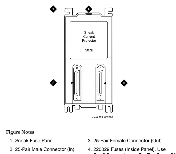
■ Install Sneak Fuse Panels 2-8
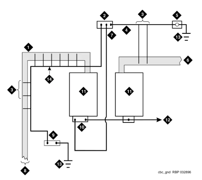
■ Install Coupled Bonding Conductor 2-11
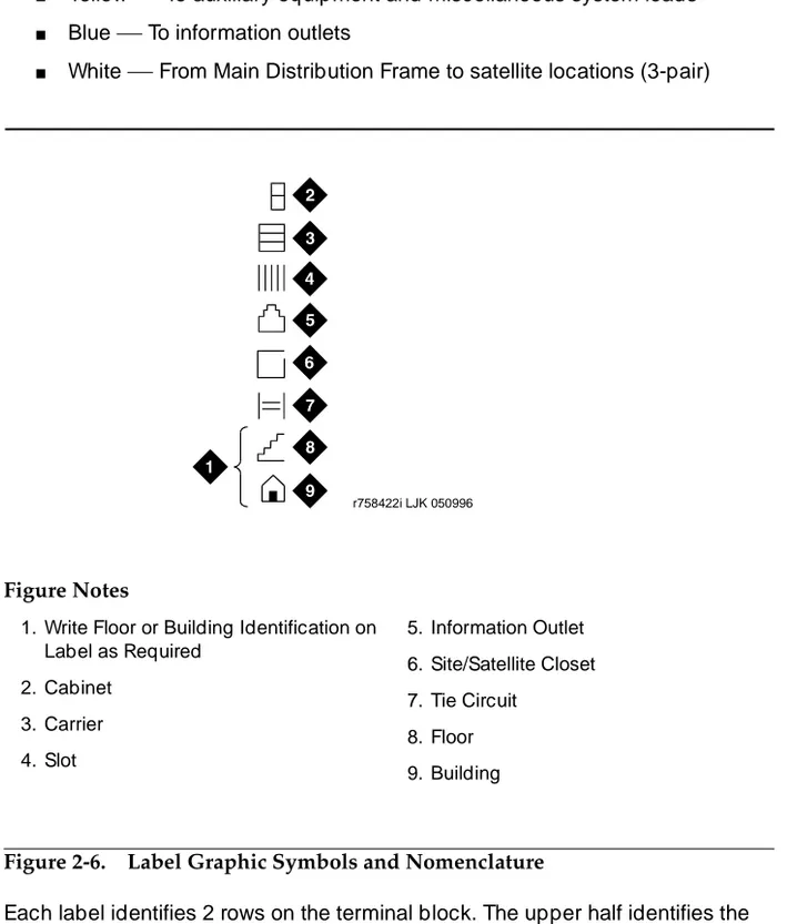
■ Label the Main Distribution Frame 2-13
3
Accessing and Activating the System 3-1■ Access the System 3-2
■ Activate the System 3-13
■ Screens and Commands 3-16
■ Administer the System 3-17
■ Administer the Circuit Packs 3-26
■ Set System Maintenance Parameters 3-29
■ Administer Attendant Console 3-30
■ Save Translations 3-30
■ Installation Completion 3-32
■ DEFINITY AUDIX System Power Procedures 3-33
4
Test the System 4-1■ Check System Status for Each Cabinet 4-2
■ Check Circuit Pack Configuration 4-4
■ Test Time Division Multiplexing Bus
in Processor Port Network 4-5
■ Test Tone-Clock Boards 4-6
■ Test Expansion Interface Circuit Packs 4-7 ■ Test Time Division Multiplexing Bus
for Each Expansion Port Network 4-8
■ Test Tone-Clock for Each Expansion Port Network 4-9 ■ Test Tone-Clock Interchange for Each
Expansion Port Network 4-9
■ Test Expansion Interface Exchange for
Contents
v
■ Check Circuit Pack Configuration 4-11
■ Save Translations, if Required 4-11
■ Next Steps 4-12
5
Install and Wire Telephones andOther Equipment 5-1
■ Voice and Data Terminals 5-1
■ Telephone Connection Example 5-1
■ Analog Station or 2-Wire Digital Station Example 5-4
■ Analog Tie Trunk Example 5-5
■ Digital Tie Trunk Example 5-6
■ DS1 Tie Trunk Example 5-7
■ Auxiliary Connector Outputs 5-9
■ Three-Pair and Four-Pair Modularity 5-11
■ Adjunct Power Connections 5-15
■ Attendant Console 5-17
■ Install 26B1 Selector Console 5-18
■ Connect External Alarm Indicators 5-18
■ Install Remote Network Interface 5-19
■ Install Off-Premises Station Wiring 5-21
■ Install Off-Premises or Out-of-Building Stations 5-22 ■ Install Emergency Transfer Units and
Associated Telephones 5-28
■ Install External Ringing 5-37
■ Install Queue Warning Indicator 5-37
■ Install Adjuncts and Peripherals 5-37
■ Install the 1145B Power Supply 5-38
■ 1151A1 and 1151A2 Power Supplies 5-47
■ CAMA/E911 Installation 5-50
■ Install the BRI Terminating Resistor 5-58
■ Install Multi-point Adapters 5-62
■ Connect Stratum 3 Clock 5-65
■ DEFINITY Wireless Business System 5-71
■ Cellular Business System 5-71
■ Forum PCM 5-71
■ Connect Modem to Telephone Network 5-72
■ List of Circuit Packs 5-76
■ Add DCS Interface 5-81
■ Add ISDN — PRI 5-85
■ Add Packet Bus Support to R8si 5-87
■ Add CallVisor ASAI 5-93
■ Add ISDN—BRI 5-95
■ Add IP Interface Assembly 5-96
■ Installing an Integrated Channel
Service Unit (ICSU) Module 5-129
■ Installing a 3150/3170 Channel Service Unit 5-133 ■ Connector and Cable Diagrams (Pinout Charts) 5-135
6
Test Telephones and Other Equipment 6-1■ Make Test Calls 6-2
■ Test 302C Attendant Console 6-2
■ Test External Ringing 6-3
■ Test Queue Warning Indicator 6-3
■ Test Integrated Announcement 6-3
■ Test Music-on-Hold 6-4
■ Test Emergency Transfer 6-4
■ Test Remote Access Interface 6-4
■ Test Basic Rate Interface 6-5
■ Test C-LAN Board 6-5
A
Option Switch Settings A-1■ Data Module Option Switch Settings A-1
■ 7400D Data Module Option Settings A-3
■ Add Pooled Modem A-5
■ Printer Option Settings A-8
■ Call Detail Recording Option Settings A-11
■ AUDIX Interface Option Settings A-11
■ TN760D Tie Trunk Circuit Pack Option Settings A-12
Contents
vii
B
Connecting and Handling Fiber Optic Cables B-1■ LASER Product B-1
■ Optical Cross-Connect Hardware B-2
■ Labels for Fiber Optic Cables B-8
■ Cleaning Fiber Optic Cables B-8
C
Connector and Cable Diagrams C-1D
Access Security Gateway D-1■ Using the ASG Mobile D-2
E
UPS Installation for SCC EPNA-Carrier Cabinet E-1
■ Parts List E-2
■ Connect the UPS E-2
■ Wire the 700A8 Plug E-3
■ Make the Remaining Connections E-4
■ Administer the EDA E-8
■ Load Test and Verify Alarms E-9
GL
Glossary and Abbreviations GL-1About This Book
ix
About This Book
This document provides procedures and information for installing and initially
testing the DEFINITY® Release 8.2si and Release 8.2si with memory system
configurations. This document also provides information on power and peripheral equipment that connects directly to a system.
This document covers information related to DEFINITY ECS Release 8.2. For
details about changes for Release 8.2, refer to DEFINITY Enterprise
Communications Server Release 8.2, Change Description.
The following conventions describe the systems referred to in this document.
■ The word system, is a general term encompassing Release 8.2 and
includes references to the DEFINITY Enterprise Communications Server.
■ DEFINITY Systems are called: Release 8; Release 8si + memory; and
Release 8si.
■ All occurrences of Release 8si, and Release 8si + memory are called
Release 8si unless a specific configuration is required to differentiate between product offerings.
■ Information in this document is applicable for Release 5 through Release
8, unless otherwise specified.
■ DEFINITY Enterprise Communications Server is abbreviated DEFINITY
ECS.
■ All physical dimensions in this book are in English (foot pound second)
Related Documents
The following documents are useful for system-related information:
■ DEFINITY Enterprise Communications Server Release 8 Administration for
Network Connectivity
■ DEFINITY Enterprise Communications Server Release 8 System
Description
■ DEFINITY Enterprise Communications Server Release 8 Maintenance for
R8r
■ DEFINITY Enterprise Communications Server Release 8 Maintenance for
R8si
■ AT&T Network and Data Connectivity Reference
■ BCS Products Security Handbook
■ DEFINITY Wireless Business System Users Guide
■ DEFINITY Wireless Business System Installation and Test Guide
■ DEFINITY Wireless Business Systems System Interface
■ DEFINITY Enterprise Communications Server Release 8 Installation and
Test for Multicarrier Cabinets
■ DEFINITY Enterprise Communications Server Release 8 Administrator’s
Guide
■ DEFINITY Enterprise Communications Server Release 8 Upgrades and
Additions for R8si
■ DEFINITY Enterprise Communications Server Release 8 Upgrades and
Additions for R8r
■ DEFINITY Enterprise Communications Server Release 8 Installation for
Adjuncts and Peripherals
How to Order Documentation
In addition to this book, other description, installation and test, maintenance, and administration documents are available. A complete list of DEFINITY documents
can be found in the Business Communications System Publications Catalog.
About This Book
xi How to Comment on This Document
How to Comment on This Document
Lucent Technologies welcomes your feedback. Please fill out the reader
comment card found at the front of this manual and return it. Your comments are of great value and help improve our documentation.
If the reader comment card is missing, FAX your comments to 1-303-538-1741 or to your Lucent Technologies representative, and mention this document’s name
and number, DEFINITY Enterprise Communication Server Release 8 Installation
and Test for Single-Carrier Cabinets.
Trademarks
This document contains references to the following Lucent Technologies trademarked products:
■ ACCUNET®
■ AUDIX®
■ Callmaster®
■ CallVisor®
■ CONVERSANT®
■ DEFINITY®
■ FORUM™
■ MEGACOM®
■ SYSTIMAX®
■ TRANSTALK™
The following products are trademarked by their appropriate vendor:
■ Audichron® is a registered trademark of Audichron Company.
■ LINX™ is a trademark of Illinois Tool Works, Inc.
■ Music Mate® is a registered trademark of Harris Corporation.
■ PagePac® is a registered trademark of Harris Corporation, Dracon
Division.
■ PORTA™ Systems is a trademark of PORTA Systems Corporation.
■ Shockwatch® is a registered trademark of Media Recovery, Incorporated.
■ Styrofoam® is a registered trademark of Styrofoam Corporation.
■ Tiltwatch® is a registered trademark of Media Recovery, Incorporated.
Standards Compliance
The equipment presented in this document complies with the following standards (as appropriate):
■ ITU-T (Formerly CCITT)
■ ECMA ■ ETSI ■ IPNS
■ DPNSS
■ National ISDN-1
■ National ISDN-2
■ ISO-9000
■ ANSI
■ FCC Part 15
■ EN55022
■ EN50081
■ EN50082
■ CISPR22
■ Australia AS3548 (AS/NZ3548)
■ Australia AS3260
■ IEC 825
■ IEC 950
■ UL 1459
■ UL 1950
■ CSA C222 Number 225
About This Book
xiii LASER Product
LASER Product
The DEFINITY ECS may contain a Class 1 LASER device if single-mode fiber optic cable is connected to a remote Expansion Port Network (EPN). The LASER device operates within the following parameters:
Maximum Power Output: -5 dBm Wavelength: 1310 nm
Mode Field Diameter: 8.8 microns
CLASS 1 LASER PRODUCT IEC 825 1993
!
CAUTION:
Use of controls or adjustments or performance of procedures other than those specified herein may result in hazardous radiation exposure.
Contact your Lucent Technologies representative for more information.
Electromagnetic Compatibility
Standards
This product complies with and conforms to the following EMC standards (as appropriate):
■ Limits and Methods of Measurements of Radio Interference
Characteristics of Information Technology Equipment, EN55022 (CISPR22), 1993
■ EN50082-1, European Generic Immunity Standard
■ FCC Parts 15 and 68
■ Australia AS3548
NOTE:
The system conforms to Class A (industrial) equipment. Voice terminals meet Class B requirements.
■ Electrostatic Discharge (ESD) IEC 1000-4-2
■ Radiated radio frequency field IEC 1000-4-3
■ Electrical Fast Transient IEC 1000-4-4
■ Lightning effects IEC 1000-4-5
■ Conducted radio frequency IEC 1000-4-6
■ Mains frequency magnetic field IEC 1000-4-8
European Union Standards
Lucent Technologies Business Communications Systems declares that the DEFINITY equipment specified in this document bearing the “CE” mark conforms to the European Union Electromagnetic Compatibility Directives.
The “CE” (Conformité Europeénne) mark indicates conformance to the European Union Electromagnetic Compatibility Directive (89/336/EEC) Low Voltage Directive (73/23/EEC) and Telecommunication Terminal Equipment (TTE). Directive (91/263/EEC) and with i-CTR3 Basic Rate Interface (BRI) and i-CTR4 Primary Rate Interface (PRI) as applicable.
The “CE” mark is applied to the following Release 8 products:
■ Global AC powered Multi-Carrier Cabinet (MCC)
■ DC powered Multi-Carrier Cabinet (MCC) with 25 Hz ring generator
■ AC powered Single-Carrier Cabinet (SCC) with 25 Hz ring generator
■ AC powered Compact Single-Carrier Cabinet (CSCC) with 25 Hz ring
generator
■ Enhanced DC Power System
Security Issues
To ensure the customer of the greatest security possible, Lucent Technologies offers services that can reduce toll fraud liabilities. Contact your Lucent Technologies representative for more security information.
About This Book
xv Where to Call for Technical Support
Where to Call for Technical Support
Use the following telephone numbers for the region in which the system is being installed:
Antistatic Protection
!
CAUTION:
When handling circuit packs or any components of a DEFINITY System, always wear an authorized wrist ground strap. Connect the strap to an approved ground such as an unpainted metal surface on the DEFINITY System.
Telephone Number
DEFINITY Helpline (feature administration and system applications)
1-800-225-7585
Lucent Technologies Toll Fraud Intervention 1-800-643-2353
Lucent Technologies National Customer Care Center 1-800-242-2121
Lucent Technologies Corporate Security 1-800-822-9009
Streamlined Implementation (for missing equipment) 1-800-772-5409
USA/Canada Technical Service Center 1-800-248-1234
ITAC 1-303-804-3777
Lucent Technologies Centers of Excellence
Asia/Pacific Regional Support Center 65-872-8686
Western Europe/Middle East/South Africa 44-1252-77-4800
Central/Eastern Europe 361-345-4334
Central/Latin America Caribbean 1-303-804-3778
Australia 61-2-9352-9090
Remove/Install Circuit Packs
!
CAUTION:
The control circuit packs with white labels cannot be removed or installed when the power is on. The port circuit packs with gray labels (older version circuit packs had purple labels) can be removed or installed when the power is on.
Federal Communications Commission
Statement
Part 68: Statement
Part 68: Answer-Supervision Signaling. Allowing this equipment to be operated in a manner that does not provide proper answer-supervision signaling is in violation of Part 68 rules. This equipment returns answer-supervision signals to the public switched network when:
■ Answered by the called station
■ Answered by the attendant
■ Routed to a recorded announcement that can be administered by the CPE
user
This equipment returns answer-supervision signals on all DID calls forwarded back to the public switched telephone network. Permissible exceptions are:
■ A call is unanswered
■ A busy tone is received
■ A reorder tone is received
Lucent Technologies attests that this registered equipment is capable of providing users access to interstate providers of operator services through the use of access codes. Modification of this equipment by call aggregators to block access dialing codes is a violation of the Telephone Operator Consumers Act of 1990.
About This Book
xvii Federal Communications Commission Statement
The REN is used to determine the quantity of devices which may be connected to the telephone line. Excessive RENs on the telephone line may result in devices not ringing in response to an incoming call. In most, but not all areas, the sum of RENs should not exceed 5.0. To be certain of the number of devices that may be connected to a line, as determined by the total RENs, contact the local telephone company.
NOTE:
REN is not required for some types of analog or digital facilities.
Means of Connection
Connection of this equipment to the telephone network is shown in the following table.
If the terminal equipment (DEFINITY® System) causes harm to the telephone
network, the telephone company will notify you in advance that temporary discontinuance of service may be required. But if advance notice is not practical, the telephone company will notify the customer as soon as possible. Also, you will be advised of your right to file a complaint with the FCC if you believe it is necessary.
The telephone company may make changes in its facilities, equipment,
operations or procedures that could affect the operation of the equipment. If this happens, the telephone company will provide advance notice in order for you to make necessary modifications to maintain uninterrupted service.
If trouble is experienced with this equipment, for repair or warranty information, please contact the Technical Service Center at 1-800-248-1234. If the equipment is causing harm to the telephone network, the telephone company may request that you disconnect the equipment until the problem is resolved.
Manufacturer’s Port
Identifier FIC Code
SOC/REN/
A.S. Code Network Jacks
Off/On Premises Station OL13C 9.0F RJ2GX,
RJ21X, RJ11C
DID Trunk 02RV2-T 0.0B RJ2GX, RJ21X
CO Trunk 02GS2 0.3A RJ21X
CO Trunk 02LS2 0.3A RJ21X
Tie Trunk TL31M 9.0F RJ2GX
1.544 Digital Interface 04DU9-B,C 6.0P RJ48C, RJ48M
1.544 Digital Interface 04DU9-BN,KN 6.0P RJ48C, RJ48M
It is recommended that repairs be performed by Lucent Technologies certified technicians.
The equipment cannot be used on public coin phone service provided by the telephone company. Connection to party line service is subject to state tariffs. Contact the state public utility commission, public service commission or corporation commission for information.
Install and Connect the Cabinets
1-1 Check Circuit Packs
1
1
Install and Connect the Cabinets
This chapter describes how to install the Release 8si Single-Carrier Cabinets.
Multicarrier Cabinet installation procedures are provided in DEFINITY Enterprise
Communications Server Release 8 Installation and Test for Multicarrier Cabinets. Floor plans and equipment layouts for typical system installations are provided in
DEFINITY Enterprise Communications Server Release 8 System Description.
Check Circuit Packs
Ensure all circuit packs are fully inserted into the proper slots according to the Customer Service Document (CSD). Report any discrepancies in circuit pack type or quantity to your Lucent Technologies representative. For detailed circuit
pack descriptions, refer to DEFINITY Enterprise Communications Server Release
8 System Description.
Release 8si systems contain a RISC-based TN790B Processor circuit pack.
Check Customer’s Order
Check the customer’s order and the shipping packing lists to confirm all
How to Correct Shipping Errors
Defective equipment and over-shipped equipment must be red-tagged and returned per the nearest Material Stocking Location (MSL) instructions.
Short-shipped reports must also be directed to the nearest Material Stocking Location (MSL). Contact the appropriate location for specific instructions. For Streamlined Implementation in the United States, call 1-800-772-5409.
Unpack and Inspect
1. Unpack the cabinets from the shipping material and inspect for damage. Report any shipping damage according to local shipping instructions.
2. Open and remove the front door and rear panels from the cabinet.
3. Verify the label near the circuit breaker on the power supply toward the rear of each cabinet corresponds to the local voltage type.
!
DANGER:
If the label is different than the voltage type at the site, notify your Lucent Technologies representative immediately for a replacement power supply. Do not, under any circumstances, connect an incorrect power supply to a power source.
Install Single-Carrier Cabinets
This section describes how to position and stack the cabinets for all reliability configurations.
!
CAUTION:
Lifting the cabinet may require two people, as it may weigh as much as 130 pounds (60 kilograms). Use caution to avoid injury.
Before beginning the cabinet installation, check the location of the AC/DC power
receptacle. The receptacle must be on a separately fused circuit not controlled
Install and Connect the Cabinets
1-3 Install Single-Carrier Cabinets
1
Refer to the serial numbers and lettered designation strips in the Customer Service Document (CSD) when stacking the cabinets. If earthquake protection is
required, skip to ‘‘Install Earthquake Protection’’. Return to this section when
finished.
!
CAUTION:
System grounding must comply with the general rules for grounding contained in Article 250 of the National Electrical Code (NEC), National Fire Protection Agency (NFPA) 70, or the applicable electric code in the country containing the equipment.
Position Cabinets (Standard Reliability)
One Cabinet Stack (Processor Port Network)
Perform this step first for all standard reliability cabinet installations.
1. Place Control Cabinet A (J58890L) on the floor in the position determined when the room layout was planned.
2. Set Port Cabinet B (J58890H) on top of Control Cabinet A.
3. Set Port Cabinet C (J58890H) on top of Port Cabinet B.
4. Set Port Cabinet D (J58890H) on top of Port Cabinet C.
5. If additional cabinet stacks are being installed, continue to the next
section. If not, proceed to ‘‘Approved Grounds’’ on page 1-5.
Two Cabinet Stacks (Expansion Port Network)
1. Place the Expansion Control Cabinet (J58890N) on the floor next to Control Cabinet A. See previous instructions.
2. Set Port Cabinet B (J58890H) on top of the Expansion Control Cabinet.
3. Set Port Cabinet C (J58890H) on top of Port Cabinet B.
4. Set Port Cabinet D (J58890H) on top of Port Cabinet C.
5. If three cabinet stacks are being installed, continue to the next section. If
not, proceed to ‘‘Approved Grounds’’ on page 1-5.
Three Cabinet Stacks (Expansion Port Network)
1. Place the second Expansion Control Cabinet (J58890N) on the floor next to the first Expansion Control Cabinet. See previous instructions.
2. Set Port Cabinet B (J58890H) on top of the Expansion Control Cabinet.
3. Set Port Cabinet C (J58890H) on top of Port Cabinet B.
4. Set Port Cabinet D (J58890H) on top of Port Cabinet C.
Position Cabinets (High or Critical Reliability)
One Cabinet Stack (Processor Port Network)
Perform this step first for all high or critical reliability cabinet installations.
1. Place Control Cabinet A (J58890L) on the floor in the position determined when the room layout was planned.
2. Set Duplicate Control Cabinet B (J58890M) on top of Control Cabinet A.
3. Set Port Cabinet C (J58890H) on top of Duplicate Control Cabinet B.
4. Set Port Cabinet D (J58890H) on top of Port Cabinet C.
5. If additional cabinet stacks are being installed, continue to the next
section. If not, skip to ‘‘Approved Grounds’’.
Two Cabinet Stacks (Expansion Port Network)
1. Place the Expansion Control Cabinet (J58890N) on the floor next to Control Cabinet A See previous instructions.
2. Set Port Cabinet B (J58890H) on top of the Expansion Control Cabinet.
3. Set Port Cabinet C (J58890H) on top of Port Cabinet B.
4. Set Port Cabinet D (J58890H) on top of Port Cabinet C.
5. If additional cabinet stacks are being installed, continue to the next
section. If not, skip to ‘‘Approved Grounds’’.
Three Cabinet Stacks (Expansion Port Network)
1. Place the second Expansion Control Cabinet (J58890N) on the floor next to the first Expansion Control Cabinet. See previous instructions.
2. Set Port Cabinet B (J58890H) on top of the second Expansion Control Cabinet.
3. Set Port Cabinet C (J58890H) on top of Port Cabinet B.
4. Set Port Cabinet D (J58890H) on top of Port Cabinet C.
Install and Connect the Cabinets
1-5 Approved Grounds
1
Approved Grounds
An approved ground is the closest acceptable medium for grounding the building entrance protector, entrance cable shield, or single-point ground of electronic telephony equipment. If more than one type of approved ground is available on the premises, the grounds must be bonded together as required in Section 250-81 of the National Electrical Code.
Grounded Building Steel
—
The metal frame of the building where it iseffectively grounded by one of the following grounds: acceptable metallic water pipe, concrete encased ground, or a ground ring.
Acceptable Water Pipe
—
A metal underground water pipe, at least 1/2-inch (1.27 cm) in diameter, in direct contact with the earth for at least 10 feet (3 m). The pipe must be electrically continuous (or made electrically continuous by bonding around insulated joints, plastic pipe, or plastic water meters) to the point where the protector ground wire is connected. A metallic underground water pipe must be supplemented by the metal frame of the building, a concrete encased ground, or a ground ring. If these grounds are not available, the water pipe ground can be supplemented by one of the following types of grounds:■ Other local metal underground systems or structures
—
Localunderground structures such as tanks and piping systems
■ Rod and pipe electrodes
—
A 5/8-inch (1.58 cm) (solid rod) or 3/4-inch(1.9 cm) (conduit or pipe) electrode driven to a minimum depth of 8 feet (2.43 m).
■ Plate electrodes
—
Must have a minimum of 2 square feet (0.185 squarem) of metallic surface exposed to the exterior soil
Concrete Encased Ground
—
An electrode encased by at least 2 inches (5.08 cm) of concrete and located within and near the bottom of a concrete foundation or footing in direct contact with the earth. The electrode must be at least 20 feet (6.1 m) of one or more steel reinforcing bars or rods 1/2-inch (1.27 cm) indiameter, or at least 20 feet (6.1 m) of bare, solid copper, 4 AWG (5.189 mm2)
wire.
Ground Ring
—
A buried ground that encircles a building or structure at a depth of at least 2.5 feet (0.76 m) below the earth’s surface. The ground ring must be atAPPROVED FLOOR GROUNDS
Approved floor grounds are those grounds on each floor of a high-rise building suitable for connection to the ground terminal in the riser closet and to the cabinet equipment single-point ground terminal. Approved floor grounds may include the following:
■ Building steel
■ The grounding conductor for the secondary side of the power transformer
feeding the floor
■ Metallic water pipes
■ Power feed metallic conduit supplying panel boards on the floor
■ A grounding point specifically provided in the building for the purpose
!
WARNING:
If the approved ground or approved floor ground can only be accessed inside a dedicated power equipment room, then
connections to this ground should be made by a licensed electrician.
Connect Cabinet Grounds
To connect the cabinet grounds on the J58890R DC Power Cabinet and the Single-Carrier Cabinets, perform the following steps. To connect the cabinet
grounds on AC-powered cabinets, skip to ‘‘Grounding AC-Powered Cabinets
Only’’ on page 1-11.
DC-Powered Cabinets Only
!
CAUTION:
System grounding shall comply with the general rules for grounding contained in Article 250 of the National Electrical Code (NEC), National Fire Protection Agency (NFPA) 70, or the applicable code at the installation site.
NOTE:
Before connecting the cabinets to the approved ground, determine the best method of grounding. Also, locate the approved ground as close to the cabinets as possible.
NOTE:
Install and Connect the Cabinets
1-7 Connect Cabinet Grounds
1
Connect DC Power Cabinet Ground
Figure 1-1. DC Power Cabinet Grounding
1. At the DC Power Cabinet, connect a 1 AWG (#70) (7 mm2) ground wire to
the GROUND DISCHARGE bar. See Figure 1-1.
2. Route the ground wire out of the cabinet and terminate it on the approved ground.
!
CAUTION:
The approved ground must be connected using the correct gauge wire, terminated with a listed clamp, and identified with a grounding tag (FORM 15657NR, or equivalent).
Figure Notes
1. DC Power Cabinet
2. To Approved Ground
3. 1 AWG (#70) (7 mm2) Wire
4. Ground Discharge Bar
3
4 1
2
Connect DC Battery Cabinet Frame Ground
Figure 1-2. Frame Ground Wiring Between Power Cabinets
1. Cut a length of 6 AWG (#40) (4 mm2) wire long enough to reach between
the DC Power Cabinet and the DC Battery Cabinet. See Figure 1-2.
2. Crimp a terminal lug on the each end of the wire. The terminal lugs are furnished as part of D-181895, kit of parts.
3. At the DC Battery Cabinet, attach the 6 AWG (#40) (4 mm2) wire to the
frame ground mounting hole using a pan head slotted screw, star washer, and hex nut. Tighten the screw securely.
4. Route the opposite end of the wire to the DC Power Cabinet.
5. Attach the 6 AWG (#40) (4 mm2) wire to the mounting hole in the top of the
cabinet. Use a pan head slotted screw, star washer, and hex nut. Tighten the screw securely.
Figure Notes
1. 6 AWG (#40) (4mm2) Wire
2. DC Battery Cabinet
3. DC Power Cabinet
4. Grounding Hole in Top of Cabinets
5. Terminal Lug (Part of D-18181895)
6. Pan Head Slotted Screw
7. Star Washer
8. Hex Nut
3
1
2
Install and Connect the Cabinets
1-9 Connect Cabinet Grounds
1
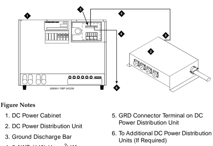
Connect DC Power Distribution Unit Ground
Figure 1-3. DC Power Distribution Unit Ground
1. Measure and cut a length of 6 AWG (#40) (4 mm2) wire long enough to
reach between the GROUND DISCHARGE bar in the DC Power Cabinet
and the GRD connector on the DC Distribution Unit. See Figure 1-3.
2. At the DC Power Cabinet, connect the 6 AWG (#40) (4 mm2) wire to the
GROUND DISCHARGE bar.
3. Route the opposite end of the wire to the DC Power Distribution Unit and connect the wire to the GRD connector.
4. Repeat Steps 2 and 3 for each remaining DC Power Distribution Unit. Figure Notes
1. DC Power Cabinet
2. DC Power Distribution Unit
3. Ground Discharge Bar
4. 6 AWG (#40) (4 mm2) Wire
5. GRD Connector Terminal on DC Power Distribution Unit
6. To Additional DC Power Distribution Units (If Required)
Connect Single-Carrier Cabinet Ground
Figure 1-4. Single-Carrier Cabinet Ground
1. Cut a length of 6 AWG (#40) (4 mm2) wire long enough to reach between
the GROUND DISCHARGE bar on the DC Power Cabinet and the
single-point ground block on the Control Cabinet (bottom cabinet in Figure
1-4).
2. At the DC Power Cabinet, connect the wire to the GROUND DISCHARGE bar.
3. Route the wire to Control Cabinet and connect to the single-point ground block.
4. Repeat for each Control Cabinet in the system room (duplicated Control Cabinet and Expansion Control Cabinet).
Figure Notes
1. 6 AWG (#40) (4 mm2) Wire
2. Control Cabinet (Cabinet A)
3. Single-Point Ground Block
4. To Additional Control Cabinets in Same Room
5. DC Power Cabinet
6. Ground Discharge Bar
4 5
1
1 6
dc_rect4 RBP 032896 Off Off
On On Off Off On On
2
Install and Connect the Cabinets
1-11 Connect Cabinet Grounds
1
Grounding AC-Powered Cabinets Only
!
CAUTION:
System grounding shall comply with the general rules for grounding contained in Article 250 of the National Electrical Code (NEC), National Fire Protection Agency (NFPA) 70, or the applicable code at the installation site.
NOTE:
Before connecting the cabinets to the approved ground, determine the
best method of grounding. See ‘‘Approved Grounds’’ on page 1-5. Also,
locate the approved ground as close to the cabinets as possible.
NOTE:
The ground plates and cabinet clips are installed later in this chapter.
1. Measure and cut a length of 6 AWG (#40) (4 mm2) wire long enough to
reach between the cabinet stack single-point ground block and the
approved ground. See Figure 1-5.
2. At the lower left rear of the Control Cabinet (Cabinet A), connect the
6 AWG (#40) (4 mm2) ground wire to the cabinet stack single-point ground
block.
3. Run the ground wire to the approved ground and attach securely.
4. Repeat Steps 1-3 for each Expansion Control Cabinet.
NOTE:
If the Expansion Control Cabinet is remotely located from Cabinet A
(in a separate room or building), run the 6 AWG (#40) (4 mm2)
cabinet ground wire to an approved protective ground.
5. At Cabinet A, connect a 10 AWG (#25) (2.5 mm2) wire to the single-point
ground block. The 10 AWG (#25) (2.5 mm2) wire must be long enough to
reach the telecommunications cables at the rear of the system cabinets, follow these cables to the Main Distribution Frame (MDF), and to terminate at the Coupled Bonding Conductor (CBC).
The Coupled Bonding Conductor (CBC) wires are installed and terminated in
Single-Carrier Cabinet Ground
Figure 1-5. Typical AC Power and Ground Layout
—
RearFigure Notes
1. Cabinet Stack 1 Control Cabinet A
2. Circuit Breaker
3. AC Power Receptacle
4. Cabinet Stack Single-Point Ground Block
5. 8-Foot (2.5 Meters) Power Cord
6. National Electrical Manufacturers Association (NEMA) 5-15 or 5-20 Receptacle or Equivalent
7. 6 AWG (#40) (4 mm2) Ground Wire
to Approved Ground
8. 10 AWG (#25) (2.5 mm2) Wire to
Coupled Bonding Conductor
3
4
5 1
8 2
7
On
Off On
Off
6
Install and Connect the Cabinets
1-13 Connect AC Power
1
Connect AC Power
Set the Ringer Frequency
The default ringer frequency setting on the 1217A power supply for North America is 20 Hz and the international setting can be either 20 Hz or 25 Hz. To set the ringer frequency on the 1217A power supply:
!
CAUTION:
When adding or replacing any hardware, be sure to ground yourself against electrostatic discharge (ESD) by wearing a grounded wrist strap.
1. Power down AUDIX and any other circuit pack that might be running an application.
2. Power down the cabinet.
3. Release both latches on the power supply and slide the unit out of the cabinet.
4. Observe the ring frequency switch label on the side of the power supply and locate the switch on the bottom.
5. Set the ring frequency select switch to the appropriate frequency setting.
6. Slide the power supply back into the slot and ensure that both latches snap closed.
Connect the Power Cord into the Power
Receptacle
1. Provide one receptacle per Single-Carrier Cabinet.
2. Verify the circuit breakers are OFF.
3. Plug the cabinet AC power cord into the AC power receptacle on the rear of each cabinet.
4. Plug the opposite end of each AC power cord into the appropriate AC power receptacle in the equipment room.
NOTE:
Connect DC Power
The following procedures apply to both the Processor Port Networks (PPN) and Expansion Port Networks (EPN).
DC Power Connections
A 30 foot (9 m) cable connects to each cabinet. A special connector on one end of the cable is plugged into the cabinet power connector. The cable must be cut to length and terminated inside the J58890R DC Power Cabinet.
Each rectifier assembly can supply up to 50 Amps of DC current. A minimum of two rectifiers are installed in each DC Power Cabinet to supply a total of 100 Amps. A third rectifier assembly can be installed and is used as a backup (N+1). Each Single-Carrier Cabinet can pull up to 18 Amps. Up to three DC Power Cabinets can be stacked to supply power to Single-Carrier Cabinet stacks.
Figure 1-6 shows a typical power and ground layout for a DC-powered system without a J58890CG DC Power Distribution Unit. The J58890CG is required if the
distance between the DC Power Cabinet(s) is greater than 30 feet (9 m). Figure
1-7 shows a typical power and ground layout for a DC-powered system
containing a DC power distribution unit.
Connect AC Power to DC Power Cabinet
1. Ensure the associated circuit breakers at the AC power panel are OFF.
2. Have an electrician connect AC power leads to the rectifiers using the instructions provided with the rectifiers in the DC Power Cabinet. Each rectifier should have its own branch circuit. Terminate leads on the AC INPUT terminal block of each rectifier.
!
CAUTION:
Install and Connect the Cabinets
1-15 Connect DC Power
1
DC Power Connections
Figure 1-6. Typical DC Power Connections
Figure Notes
1. System Cabinet Stack
2. DC Power Cabinet
3. White Wires
4. Green Ground Wires and Black Wires Connect to the -48 VDC Return Bus
5. -48 VDC Bus
6. Connect White Wires to Circuit Breakers
7. DC Power Cable (H600-436, G1) to Power Connector on Each Cabinet. Cut to Length and Crimp a Ring Terminal Onto Each Wire
8. 30 Feet (9 m) Maximum
9. Route Cables Through Sliding Door
10. Circuit Breaker
11. Supplied #10-32 Screw, #10 Star Washer, and #10-32 Hex Nut
DC Power Connections with DC Distribution
Unit
A 10 foot (3 meter) power cord is equipped with the appropriate connectors. In
the configuration shown in Figure 1-7, each cabinet stack has a DC Power
Distribution Unit associated with it.
Figure 1-7. Connections Using DC Power Distribution Unit
Figure Notes
1. System Cabinet Stack
2. DC Power Cabinet
3. DC Power Distribution Unit (Position to the Right of the Cabinet Stack)
4. White Wire (Connect to Circuit Breaker). See Inset.
5. Green Ground Wire and Black Wire Connect to the -48 VDC Return Bus
6. -48 VDC Bus
7. Inset
8. 12 Inches (30.5 cm) From Floor to DC Power Distribution Unit
9. DC Power Cable to Power Connector on Each Cabinet
10. DC Power Distribution Unit Power Cord (Route to Rear of DC Power Cabinet)
11. Route Power Cord Through Sliding Door
12. Circuit Breaker
13. Supplied #10-32 Screw, #10 Star Washer, and #10-32 Hex Nut
Install and Connect the Cabinets
1-17 Connect DC Power
1
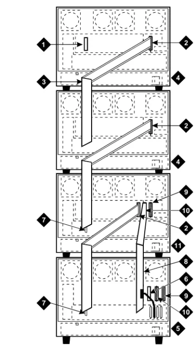
Stacking DC Power Cabinets
Up to three DC Power Cabinets can be stacked to supply power to Single-Carrier
Cabinet stacks. See Figure 1-8.
Figure 1-8. DC Power Cabinet Stack
—
RearFigure Notes
1. DC Power Cabinet Stack
2. DC Power Cables Daisy Chained Between DC Power Cabinets
3. Connect to -48 VDC Bus
4. Connect to -48 VDC Return Bus
5. Inset Applies to -48 VDC and -48 VDC Return Buses in All Three DC Power Cabinets
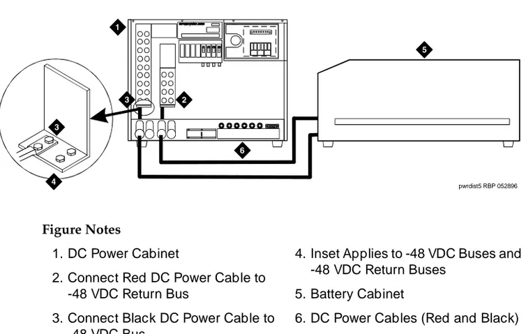
Connect Battery Cabinet
Figure 1-9 shows typical connections from the DC Battery Cabinet to the DC Power Cabinet.
Figure 1-9. DC Battery to DC Power Cabinet Connections
!
CAUTION:
Power is present in the cabinet even if the AC power cable is unplugged. Turn off the main circuit breaker on the front of the cabinet when procedures require ALL power to be removed from the cabinet.
Figure Notes
1. DC Power Cabinet
2. Connect Red DC Power Cable to -48 VDC Return Bus
3. Connect Black DC Power Cable to -48 VDC Bus
4. Inset Applies to -48 VDC Buses and -48 VDC Return Buses
5. Battery Cabinet
6. DC Power Cables (Red and Black)
Install and Connect the Cabinets
1-19 Connect Optional Battery Leads
1
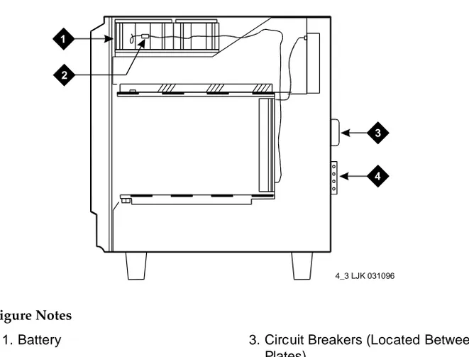
Connect Optional Battery Leads
To prevent the internal batteries from discharging, the Control Cabinet is shipped with the battery leads disconnected.
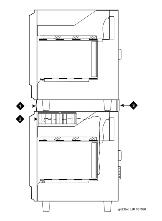
Figure 1-10. Control Cabinet Battery Location
—
Right Side1. Set the circuit breakers OFF. See Figure 1-10.
2. Connect the battery leads. The battery is near the top of the carrier toward the front-right. The battery leads are located next to the battery and are accessible from the front of the cabinet.
Figure Notes
1. Battery
2. Battery Lead Connector
3. Circuit Breakers (Located Between Plates)
4. Cabinet Single-Point Ground Block
3
4 1
2
Connect AC Power to Stratum 3 Clock
Cabinet
The clock cabinet requires a 120 VAC, 15 Amp receptacle. The green wire ground provided by the receptacle is sufficient. The clock cabinet does not require a ground connection back to the single-point ground.
Check and Connect Commercial AC Power
Before powering up the system, check the AC power using a KS-20599 digital voltmeter (DVM) (or equivalent).
1. Set the DVM to the 250 volt range.
2. Carefully measure the voltage between the hot and neutral side of the receptacle. The neutral wire is white, the hot wire is black.
3. Verify the meter reads 106 to 128 VAC. If not, have a qualified electrician correct the problem.
4. Measure the voltage between the neutral and ground side of the receptacle. The ground wire is green.
5. Verify the meter reads 0 VAC. If not, have a qualified electrician correct the problem.
6. Set all cabinet power modules OFF. Plug the AC power cable into the receptacle.
Connect DC Power and Ground to
Stratum 3 Clock Cabinet
The clock cabinet should be powered from the same DC power plant as the DEFINITY System. The clock cabinet must be grounded to the DC power plant.
Connect Clock Cabinet Grounding
1. Measure and cut a 6 AWG (#40) (4 mm2) wire long enough to reach from
the clock cabinet to the ground discharge bar in the DC power plant.
2. Insert one end of the wire into the ground lug on the clock cabinet and tighten the screw.
3. Attach the lug to the receptacle cover. Be sure the lug and cabinet ground wires connect to separate screws on the receptacle cover.
Install and Connect the Cabinets
1-21 Connect Time Division Multiplexing Bus Cables
1
Connect Stratum 3 Clock DC Power
1. Set the clock cabinet circuit breaker at the DC power plant OFF.
2. At the clock cabinet, connect a 6 AWG (#40) (4 mm2) ground wire to the
-48V terminal on the terminal strip.
3. At the clock cabinet, connect a 6 AWG (#40) (4 mm2) wire to the -48VRTN
terminal on the terminal strip.
4. Route the wires out of the cabinet and to the DC power plant.
5. At the DC power plant, connect the -48V wire to the DC OUTPUT circuit breaker.
6. At the DC power plant, connect the -48VRTN wire to the DISCH GRD bar.
Connect Time Division Multiplexing
Bus Cables
If the cabinet stack contains only one Single-Carrier Cabinet, skip this section
and proceed to ‘‘Verify Port Cabinet Address Plugs’’ on page 1-26.
Locate the white fabric-covered Time Division Multiplexing (TDM) bus cable on the rear of the cabinets.
Standard Reliability Processor Port Network
One cabinet stack:
1. Remove the Time Division Multiplexing (TDM) Bus Terminator (AHF110) from Slot 18 of the Control Cabinet (Processor Port Network (PPN)) and
move it to Slot 17 on the top Port Cabinet. See Figure 1-11.
2. Connect the supplied Time Division Multiplexing (TDM) Bus Cables
High or Critical Reliability Processor Port
Network
Two cabinet stacks:
1. Remove the Time Division Multiplexing (TDM) Bus Terminator from Slot 18 of Control Cabinet A (Processor Port Network (PPN)) and move it to Slot 18
of Control Cabinet B. See Figure 1-12.
2. Connect the supplied Time Division Multiplexing (TDM) Bus Cables (WP-91716 L3) from Cabinet A to Cabinet B as shown.
High or Critical Reliability Processor Port
Network
Three cabinet stacks:
1. Remove the Time Division Multiplexing (TDM) Bus Terminator from Slot 18 of Control Cabinet A (Processor Port Network (PPN)) and move it to Slot 17
on the top port cabinet. See Figure 1-13.
2. Connect the supplied TDM Bus Cables (WP-91716 L3) as shown.
Expansion Port Network (All Reliability Options)
1. Remove the TDM Bus Terminator from Slot 18 of Control Cabinet A (PPN)
and move it to Slot 17 on the top port cabinet. See Figure 1-12.
Install and Connect the Cabinets
1-23 Connect Time Division Multiplexing Bus Cables
1
Figure 1-11. Connections for Standard Reliability Systems
Figure Notes
1. AHF110 TDM Bus Terminator (Slot 17)
2. TDM/Local Area Network (TDM/LAN) Pinfield (Slot 00)
3. TDM Bus Cable WP-91716 L3
4. Port Cabinet (Standard Reliability)
5. Control Cabinet A Position
6. AHF110 TDM Bus Terminator (Slot 03)
7. Slot 18
3
3
3
7
4
4
4
5
1 2
2
2
6
Figure 1-12. Connections for High or Critical Reliability Systems Figure Notes
1. AHF110 TDM Bus Terminator (Slot 17)
2. TDM/Local Area Network (TDM/LAN) Pinfield (Slot 00)
3. TDM bus Cable (WP-91716 L3)
4. Port Cabinet
5. Control Cabinet A Position
6. AHF110 TDM Bus Terminator (Slot 01)
7. Slot 18
8. Inter-Cabinet Cables (ICC) A, B and C (H600-248-G1)
9. Inter-Cabinet Cable (ICC) A
10. Inter-Cabinet Cable (ICC) B
11. Duplicated Control Cabinet B Position
3
7 7
4
4
11
8
5
1 2
2
9
9 6 2 10
10
Install and Connect the Cabinets
1-25 Connect Time Division Multiplexing Bus Cables
1
Figure 1-13. Connections for High or Critical Reliability Systems
Figure Notes
1. AHF110 TDM Bus Terminator (Slot 17)
2. TDM/Local Area Network (TDM/LAN) Pinfield (Slot 00)
3. TDM bus Cable (WP-91716 L3)
4. Port Cabinet
5. Control Cabinet A Position
6. AHF110 TDM Bus Terminator (Slot 03)
7. Slot 18
8. Inter-Cabinet Cables (ICC) B and C (H600-259-G1)
9. Duplicated Control Cabinet B Position
3
3
3
7
4
4
9
5
1 2
2
2 8
8
6
Verify Port Cabinet Address Plugs
The address plug is a jumper field on port cabinets only. The address plug is located on the far right hand side of the backplane, to the right of slot 00.
A group of six pins is labeled for the cabinet (carrier) jumper connections. Verify
the address plug for each port carrier is in the correct location for that carrier.
See Figure 1-14. The factory default setting is “B” (Callout 2 in Figure 1-14).
Figure 1-14. Port Cabinet Address Plug Location — Cabinet Rear
Figure Notes
1. Address Plug (Shown Set to Carrier D)
2. Carrier B Jumper Location (Default)
3. Carrier C Jumper Location
4. Right Edge of Backplane
5. Right Edge of Cabinet
6. Backplane Slot 00
7. To Connector Panel
3
4 5
1 6
2
7
Install and Connect the Cabinets
1-27 Install Rear Panels
1
Install Rear Panels
Figure 1-15. Rear Panel Screw Locations
1. Install the rear panels and loosely thread each screw. See Figure 1-15.
2. For unstacked cabinets, tighten the screws securely.
For a stack of cabinets, allow the screws labeled Callout 4 to remain loose.
These screws are tightened when the ground plates are installed.
3. Be sure the Time Division Multiplexing (TDM) bus cables and the Inter-Cabinet Cables (ICC) are not pinched by the panels. Also be sure the cables are routed through the channels provided on the rear panels. Figure Notes
1. Cabinet in A Position (No Ground Plate is Installed on an Unstacked Cabinet)
2. Rear Ground Plate (Attached Between Stacked Cabinets)
3. Cabinet in B Position
4. Screws to Loosen
2 1
3
4 4
Install Ground Plates
Ground plates are installed between stacked cabinets, provide the ground connection between cabinets, provide radio frequency (RF) radiation protection, and help stabilize the cabinets.
Install Rear Ground Plates (Systems with
Earthquake Protection)
1. Loosen the four screws at the bottom of the top cabinet and at the top of
the cabinet underneath the top cabinet. See Figure 1-15.
2. Align the mounting holes in the rear ground plate over the bottom screws
in the top cabinet. See Figure 1-16.
3. Align the mounting holes in the ground plate with the four holes at the top of the cabinet below the top cabinet. Slide the mounting plate down to seat on the screws.
4. Check all Time Division Multiplexing (TDM) bus cables and the Inter Cabinet Cables (ICC) to be sure they are not pinched by the plates.
5. Repeat Steps 1-3 until the rear ground plates are installed between all stacked cabinets.
6. Do not tighten the screws yet.
Install Front Ground Plates (Systems with
Radiation Shielding and Earthquake Protection)
Use the front ground plate instead of the cabinet clip to attach the cabinets to
each other. Use one front ground plate between two stacked cabinets.
1. At the front of the cabinets, align the holes in the top of the front ground plate with the holes at the bottom of the upper cabinet, and insert the four
screws. Do not tighten the screws yet. See Figure 1-16.
2. At the front of the cabinets, align the holes in the bottom of the front ground plate with the holes at the top of the lower cabinet. Insert the four supplied #12-24 x 1/2-inch (1.27 cm) thread-forming screws. Do not tighten the screws yet.
3. Repeat Steps 1 and 2 until all stacked cabinets are fastened together.
Install and Connect the Cabinets
1-29 Install Ground Plates
1
Figure 1-16. Rear Ground Plate and Front Plate or Cabinet Clip
—
Side ViewFigure Notes
1. Front Ground Plate or Cabinet Clip
2. Battery
3. Rear Ground Plate
3
2 1
Install Cabinet Clips (Systems without
Earthquake Protection)
A cabinet clip is required between each pair of stacked cabinets.
At the front of the cabinets, install a cabinet clip between each pair of cabinets by hooking the clip into the slot of the upper cabinet and snapping the straight
leg of the clip into the slot on the lower cabinet. See Figure 1-17.
Figure 1-17. Location of Cabinet Clips
Figure Notes
1. Control Cabinet
2. Port Cabinet or Duplicated Control Cabinet
3. Port Cabinet
4. Port Cabinet
Install and Connect the Cabinets
1-31 Connect System Cables
1
Connect System Cables
Inter-Cabinet Cables (High or Critical Reliability)
1. Connect the cables for critical reliability Expansion Port Networks (EPNs)
as shown in Figure 1-12 and in Table 1-1 below.
2. Connect the cables for high or critical reliability Processor Port Networks
(PPNs) as shown in Figure 1-13.
Fiber Optic Cables
The fiber optic cables are connected to the Main Distribution Frame (MDF) in
Chapter 2, ‘‘Install Telecommunications Cabling’’. Refer to Appendix B,
‘‘Connecting and Handling Fiber Optic Cables’’ for information about connecting to optical cross-connect hardware and routing through lightguide equipment.
The DEFINITY ECS may contain a Class 1 LASER device if single-mode fiber optic cable is connected to a remote Expansion Port Network (EPN). The LASER device operates within the following parameters:
Maximum Power Output: -5 dBm Wavelength: 1310 nm
Mode Field Diameter: 8.8 microns
CLASS 1 LASER PRODUCT IEC 825 1993
!
CAUTION:
Use of controls or adjustments or performance of procedures other than those specified herein may result in hazardous radiation exposure.
Contact your Lucent Technologies representative for more information.
Table 1-1. Inter-Cabinet Cable Connections
From Cabinet A To Cabinet B
Cabinet Carrier Connection Carrier Connection
Processor Port Network (PPN)
J58890L (ICC) B J58890M (ICC) B
(ICC) C (ICC) C
Expansion Port Network (EPN)
J58890N (ICC) A J58890H (ICC) A
Fiber Optic Cable Connections
The Customer Service Document (CSD) provides an “Inter-Cabinet Cable Running List.” Each row on the list represents a cable connection. Use the running list to determine where to connect each fiber optic cable.
Multi-Mode Fiber Optic Connections
The following components are used in multi-mode fiber optic connections:
■ Expansion Interface (EI) circuit packs in port slots in cabinet carriers
■ Cables from each interface circuit pack to each port slot connector
■ The 9823A lightwave transceiver transmits up to 4,900 feet (1.5 km). The
9823B lightwave transceiver transmits up to 25,000 feet (7.6 km).
■ Multi-mode fiber optic cable consists of two separate 62.5 micron
diameter fiber optic cables or 50 micron diameter fiber optic cables.
Single-Mode Fiber Optic Connections
The following components are used in single-mode fiber optic connections:
■ Expansion Interface (EI) circuit packs in port slots in cabinet carriers
■ Cables from each interface circuit pack to each port slot connector
■ The 300A lightwave transceivers transmits light up to 115,000 feet (35
km). Fiber loss must be less than 17dB. Saturation may occur if distances are short; attenuators may be required if the total loss on the fiber link is less than 10dBm. An Optical Time Domain Reflectometer (OTDR) test is recommended to determine specific fiber optic hardware requirements.
■ Single-mode fiber optic cable consists of two separate 8 to 10 micron core
cables.
NOTE:
Install and Connect the Cabinets
1-33 Connect System Cables
1
Recommended Cable Routing
1. Route the fiber optic cable up toward the top of the cabinet. The excess cable should be looped and draped from the B25A cable clamp on the
top ground plate in the stack. See Figure 1-18.
2. Dress the cable by tie wrapping it to the outside of the B25A cable clamp.
!
CAUTION:
Do not route fiber optic cables and the B25A cables together.
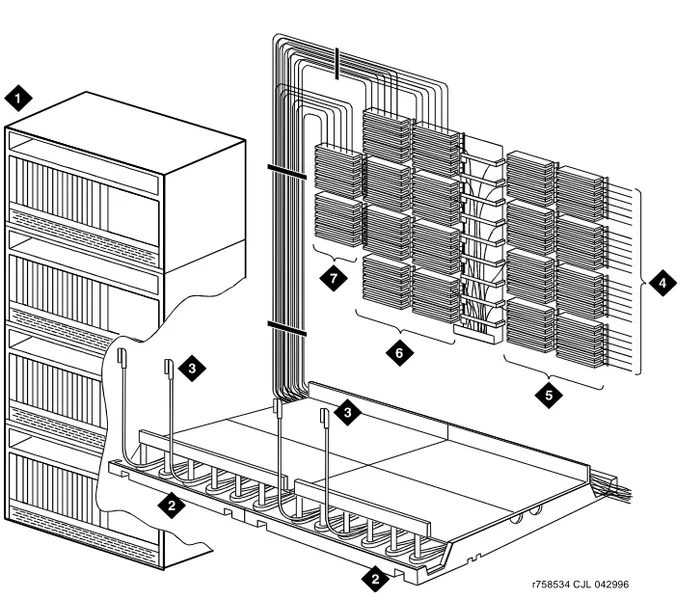
Figure 1-18. Single-Carrier Cabinet Fiber Routing
Figure Notes
1. Supplied B25A Cables
2. Loop and Drape Excess Fiber Optic Cable
3. Fiber Optic Cable Sheath
4. Port Cabinet
5. Control Cabinet
3
4 4
4 4
4 4
5 5
1
Standard Reliability Fiber Connections
Connect and route the fiber optic cable as shown in the cable running list. See
Figure 1-19 for a sample cable routing.
Figure 1-19. Connections to Standard Reliability Systems
Figure Notes
1. Control Cabinet
2. Port Cabinet
3. Expansion Control Cabinet
4. Cabinet Stack 1
5. Cabinet Stack 2
6. Cabinet Stack 3
18 17 16 15 14 13 12 11 10 9 8 7 6 5 4 3 2 1 18 17 16 15 14 13 12 11 10 9 8 76 5 4 3 2 1
3
18 17 16 15 14 13 12 11 10 9 8 76 5 4 3 2 1 18 17 16 15 14 13 12 11 10 9 8 76 5 4 3 2 1 18 17 16 15 14 13 12 11 10 9 8 7 6 5 4 3 2 1
18 17 16 15 14 13 12 11 10 9 8 76 5 4 3 2 1
18 17 16 15 14 13 12 11 10 9 8 76 5 4 3 2 1
18 17 16 15 14 13 12 11 10 9 8 76 5 4 3 2 1 18 17 16 15 14 13 12 11 10 9 8 7 6 5 4 3 2 1
18 17 16 15 14 13 12 11 10 9 8 76 5 4 3 2 1 18 17 16 15 14 13 12 11 10 9 8 7 6 5 4 3 2 1
2
16 15 14 13 12 11 10 9 8 7 6 5 4 3 2 1 Terminal
Install and Connect the Cabinets
1-35 Connect System Cables
1
High Reliability Fiber Connections
Connect and route the fiber optic cable as shown in the cable running list. See
Figure 1-20 for a sample cable routing.
Figure 1-20. Connections to High Reliability Systems
Figure Notes
1. Control Cabinet
2. Duplicate Control Cabinet
3. Port Cabinet
4. Expansion Control Cabinet
5. Cabinet Stack 1
6. Cabinet Stack 2
7. Cabinet Stack 3
18 17 16 15 14 13 12 11 10 9 8 7 6 5 4 3 2 1 18 17 16 15 14 13 12 11 10 9 8 7 6 5 4 3 2 1 18 17 16 15 14 13 12 11 10 9 8 7 6 5 4 3 2 1 18 17 16 15 14 13 12 11 10 9 8 7 6 5 4 3 2 1 18 17 16 15 14 13 12 11 10 9 8 7 6 5 4 3 2 1
18 17 16 15 14 13 12 11 10 9 8 7 6 5 4 3 2 1 18 17 16 15 14 13 12 11 10 9 8 7 6 5 4 3 2 1 18 17 16 15 14 13 12 11 10 9 8 7 6 5 4 3 2 1
18 17 16 15 14 13 12 11 10 9 8 7 6 5 4 3 2 1 18 17 16 15 14 13 12 11 10 9 8 7 6 5 4 3 2 1 16 15 14 13 12 11 10 9 8 7 6 5 4 3 2 1
Terminal
16 15 14 13 12 11 10 9 8 7 6 5 4 3 2 1 Terminal
Critical Reliability Fiber Connections
Connect and route the fiber optic cable as shown in the cable running list. See
Figure 1-21 for a sample cable routing.
Figure 1-21. Connections to Critical Reliability Systems
Figure Notes
1. Control Cabinet
2. Duplicate Control Cabinet
3. Port Cabinet
4. Expansion Control Cabinet
5. Cabinet Stack 1
6. Cabinet Stack 2
7. Cabinet Stack 3
18 17 16 15 14 13 12 11 10 9 8 7 6 5 4 3 2 1 18 17 16 15 14 13 12 11 10 9 8 7 6 5 4 3 2 1 18 17 16 15 14 13 12 11 10 9 8 7 6 5 4 3 2 1 18 17 16 15 14 13 12 11 10 9 8 7 6 5 4 3 2 1 18 17 16 15 14 13 12 11 10 9 8 7 6 5 4 3 2 1
18 17 16 15 14 13 12 11 10 9 8 7 6 5 4 3 2 1 18 17 16 15 14 13 12 11 10 9 8 7 6 5 4 3 2 1 18 17 16 15 14 13 12 11 10 9 8 7 6 5 4 3 2 1
18 17 16 15 14 13 12 11 10 9 8 7 6 5 4 3 2 1 18 17 16 15 14 13 12 11 10 9 8 7 6 5 4 3 2 1 16 15 14 13 12 11 10 9 8 7 6 5 4 3 2 1
Terminal
16 15 14 13 12 11 10 9 8 7 6 5 4 3 2 1 Terminal
Install and Connect the Cabinets
1-37 Install Earthquake Protection
1
Install Earthquake Protection
Earthquake protection only installs on Single-Carrier Cabinets.
Figure 1-22. Front Mounting Angle Location
1. Position the Control Cabinet (J58890L) in the position it is to occupy when the installation is complete. Be sure the cabinet is level.
2. Using a pencil or marker and using the Front Mounting Angle as a template, mark the locations of the two floor mounting holes.
3. Move the cabinet out of the way and drill a hole 0.5-inch (1.3 cm) in diameter and 1.5 inches (3.8 cm) deep at the locations marked in Step 2.
4. Insert a concrete floor anchor (STARR part number 3425) into each hole. Figure Notes
1. #12-24x1/2-inch Thread Forming Screw
2. Control Cabinet
3. Front Mounting Angle
4. Hex Head Bolt
5. Nylon Insulating Washer
6. Concrete Floor
7. Concrete Floor Anchor
4 1
3
2
5
6
7
5. Secure the Front Mounting Angle to the floor using the short hex head bolts provided.
6. Move the cabinet back into place.
7. At the rear of the cabinet, remove the two hole plugs from the bottom of
the cabinet. See Figure 1-23.
8. Insert a pencil or marker through the holes in the bottom of the cabinet and mark the floor directly beneath each hole.
9. Move the cabinet out of the way and drill a hole 0.5-inch (1.27 cm) in diameter and 1.5 inches (3.8 cm) deep at the locations marked in Step 8.
10. Insert a concrete floor anchor (STARR part number 3425) into each hole.
11. Move the cabinet back into place and align with the Front Mounting Angle.
12. Attach the cabinet to the Front Mounting Angle using the four supplied
Install and Connect the Cabinets
1-39 Install Earthquake Protection
1
Figure 1-23. Cabinet Earthquake Mounting — Rear View
13. Lay the supplied Stiffener on the bottom rear of the cabinet and align with
the holes in the bottom of the cabinet. See Figure 1-23.
14. Slide a nylon washer onto each of the two supplied long hex head bolts.
15. Insert the bolts through the Stiffener and thread into the concrete floor anchor. Tighten securely.
NOTE:
If critical reliability is installed, the Expansion Control Cabinet sets on the floor, next to Control Cabinet A. Repeat the above procedures. Figure Notes
1. Cabinet
2. Nylon Insulating Washer (2 Required)
3. Long Hex Head Bolt (2 Required)
4. Stiffener
5. Cabinet Foot
6. Floor Plugs (Remove)
7. Concrete Floor Anchor
8. Concrete Floor
3 4
5 1
8 2
7
On
Off On
Off
6
Install Telecommunications Cabling
2-1 Equipment Room Hardware
2
2
Install Telecommunications Cabling
Equipment Room Hardware
SYSTIMAX 110-type hardware is used for the Main Distribution Frame (MDF). 110-type hardware is available in two basic types: the 110A and 110P. The 110A requires less wall space than the 110P. The 110P includes horizontal and vertical cable troughs for managing cross-connect cables. The system is connected to the MDF with the supplied B25A male to female 25-pair cables. The cables are provided in 10-foot (3 m) and 15-foot (4.5 m) lengths.
Refer to DEF