NOTICE
The information contained in this document is believed to be accurate in all respects but is not warranted by Mitel Corporation (MITEL). The information is subject to change without notice and should not be construed in any way as a commitment by MITEL or any of its affiliates or subsidiaries. MITEL and its affiliates and subsidiaries assume no responsibility for any error or omissions in this document. Revisions of this document or new editions of it may be issued to incorporate any such changes.
Nothing in this document may be reproduced in any manner, either wholly or in part for any use whatsoever, without written permission from Mitel Corporation.
Host Command Interface, HCI, MITEL, MiTAI, NuPoint Messenger, NuPoint Voice, NuPoint Fax, NuPoint Agent, OnePoint Messenger, SUPERSET, SX-200 and SX-2000 are trademarks of Mitel Corporation. Windows 95 and Windows NT are trademarks of Microsoft Corporation. INTEL and Pentium are trademarks of Intel Corporation.
All other product names specified in this document are trademarks of their corresponding owners.
OnePoint Messenger/SX-200 Guide OnePoint Messenger Release 2.0 Part number: 9164-120-115-NA, Rev. A
August 9, 2000
â, ä, Trademark of MITEL Corporation.
Ó Copyright 2000, MITEL Corporation. All rights reserved.
OnePoint Messenger/SX-200 Integration Guide, Rev. A, 8/9/00 iii
OnePoint Messenger/SX-200 Integration Guide
Table of Contents
About This Guide ...9
How to Use This Guide ... 9
Book Organization ... 10
Chapter Organization... 10
Using Electronic and Printed Versions... 10
Conventions Used in This Guide ... 10
Keys, Commands, and Buttons ... 11
Images and Tables ... 11
Type in Commands and Screen Output... 12
Lists... 12
Notes and Cautions ... 12
Other Text Styles... 12
Other Documentation... 12
Contacting Technical Publications ... 14
1. OnePoint Messenger/SX-200 Integration Overview ...15
What Is OnePoint Messenger and Unified Messaging? ... 15
Telephony Server ... 16
Telephony Server Peripherals ... 17
Benefits of the Integration ... 18
Call Flow Overview... 18
Task Overview ... 20
Integration Strategy ... 20
2. Configuring the SX-200 PBX ...23
Overview of OnePoint Messenger Requirements ... 24
Required Forms and Settings ... 25
iv
Form 2, Feature Access Codes ... 26
Form 3, COS Definitions... 26
Form 4, System Options... 29
Form 9, Desktop Device Assignments... 30
Form 11, Data Circuit Descriptors ... 30
Form 12, Data Assignment... 31
Form 17, Hunt Group ... 31
Form 31, System Abbreviated Dial Entry... 31
Form 34, Direct I/O ... 33
Check MAI Installation and Programming ...33
Show Status Command ... 33
Examples of the Customer Data Entry (CDE) Forms ...34
3. Installing the TalkTo Card ... 39
About the TalkTo CX Card...39
SX-200 Support for Peripherals ... 40
Installing the TalkTo Card ...40
TalkTo CX Card Configuration... 43
TalkTo CX Card Settings ...43
Troubleshooting the TalkTo Card Installation...43
Changing the IRQ... 44
Changing the I/O Base Address ... 45
4. Installing Mitel Telephony Application Interface (MiTAI)... 47
What You Need to Complete this Chapter ...47
Installing MiTAI on the Telephony Server...47
Installing MiTAI on the Telephony Server... 47
Checking the Operation of the MiTAI Link to the PBX ...51
Editing the Server Hosts File ...53
5. Configuring OnePoint Messenger PBX Integration Software55
Introduction ...56OnePoint Messenger/SX-200 Integration Guide, Rev. A, 8/9/00 v
Show N Tel Telephony Applications Overview ... 56
Notification Server Configuring and Testing Overview... 57
Configuring Show N Tel with the SX-200 PBX... 59
Assigning Programs to Lines ... 61
Modifying the Phone System Definition... 63
Setting Show N Tel Parameters ... 66
Setting OnePoint System Parameters... 67
Editing Configuration Files for a Mitel PBX Integration ... 68
Editing the Server Hosts File ... 68
Editing the Telsrvr.ini file for a Mitel PBX Integration ... 69
Starting and Stopping Telephony Server... 70
Configuring OnePoint Messenger to Auto-start ... 71
Running the Telephony Applications... 71
Reassigning Lines to Other Applications... 71
vi Table of Contents
List of Figures
Figure 1-1 Network Diagram ... 16
Figure 2-1 Show Status Command Display ... 33
Figure 2-2 Form 1, System Configuration ... 34
Figure 2-3 Form 2, Feature Access Codes ... 35
Figure 2-4 Form 3, Class Of Service ... 35
Figure 2-5 Form 4, System Options/System Timers ... 36
Figure 2-6 Form 11, Data Circuit Descriptors ... 36
Figure 2-7 Form 12, Data Assignment ... 37
Figure 2-8 Form 17, Hunt Groups ... 37
Figure 2-9 Form 31, System Abbreviated Dial Entry ... 38
Figure 2-10 Form 34, Direct I/O ... 38
Figure 3-1 Windows NT Diagnostics, Resources Tab, IRQ List ... 41
Figure 3-2 Windows NT Diagnostics, I/O Port List ... 42
Figure 3-3 TalkTo Card Diagram ... 45
Figure 4-1 MiTAI Settings Dialog, Hardware Tab ... 49
Figure 4-2 MiTAI Settings Dialog, Software Tab ... 50
Figure 4-3 MiTAI Settings Dialog, Versions Tab ... 51
Figure 4-4 MiTAIX Program Window 1 ... 52
Figure 4-5 MiTAIX Program Window 2 ... 52
Figure 4-6 MiTAIX Program Window 3 ... 53
Figure 5-1 SNT Manager, Configure CTI, Device Map Tab ... 60
Figure 5-2 Show N Tel Runtime Tab, Assign Phone System ... 63
Figure 5-3 Show N Tel Setup, Phone System Tab ... 64
Figure 5-4 SNT Setup, Phone Sys Definition, Configure CTI Tab ... 65
Figure 5-5 Show N Tel, Feature Definitions Tab ... 66
Figure 5-6 Show N Tel Manager, Parameters Tab ... 67
Figure 5-7 Telsrvr.ini ... 70
OnePoint Messenger/SX-200 Integration Guide, Rev. A, 8/9/00 vii
List of Tables
Table 2-1 Form 2, Required Feature Access Codes ... 26
Table 2-3 Form 3, Additional ONS COS Features ... 27
Table 2-2 Form 3, COS Features Common to the Four COS Groups ... 27
Table 2-4 Form 3, Additional User Set COS Features ... 28
Table 2-5 Form 3, Additional MiTAI link/DNIC 2103 COS Features ... 28
Table 2-6 Form 3, Additional MWI/Pager Notification COS Features ... 28
Table 2-7 Form 4, System Options ... 29
Table 2-8 Form 11, Data Circuit Descriptor, Select Option ... 30
Table 2-9 Form 31, System Abbreviated Dial Entry ... 32
Table 2-10 Form 34, MAI Programming: Direct I/O ... 33
Table 3-1 Base Address Locations on the TalkTo Card ... 46
OnePoint Messenger/SX-200 Integration Guide, Rev. A, 8/9/00 9
About This Guide
Use this guide to integrate a OnePoint Messenger Telephony Server with a Mitel SX-200 PBX. If you are installing a turnkey TS800 Tele-phony Server, use this guide with the OnePoint MessengerGetting Started Guide. If you are installing OnePoint Messenger on a bare system, use this guide with the OnePoint MessengerInstallation Guide. This integration guide replaces Chapter 4 in that guide.
This chapter contains these sections:
How to Use This Guide
“Task Overview” on page 20 in Chapter 1 lists the sequence of tasks in the installation and integration process, noting the chapter associ-ated with the task.
OnePoint Messenger is designed to be relatively simple to implement and use. However, integrating the OnePoint Messenger Telephony Server with a Mitel PBX requires the skills of a technician with certi-fication in the programming of an SX-200 and the installation of OnePoint Messenger. While this manual lists the critical PBX fea-tures that must be enabled and contains instructions on the use of the PBX user interface, the instructions are for LIGHTWARE 17 and may not be current for your system. See the manufacturer’s program-ming guide that accompanies your PBX software. In addition, this manual does not discuss the array of monitoring, programming, and troubleshooting options available to the Mitel SX-200 installer and administrator.
Section Page
10 About This Guide Book Organization
This guide provides an overview in Chapter 1, followed by chapters organized by the most appropriate sequence of activities.
• Chapter 1 (page 15):Overview of the components, tasks, and benefits of the integration
• Chapters 2 (page 23): Configuring the SX-200 PBX
• Chapter 3 (page 39): Installing the TalkTo card on the Tele-phony Server
• Chapter 4 (page 47): Installing MiTAI on the Telephony Server
• Chapter 5 (page 55): Configuring the Telephony Server, with an overview of startup and shutdown procedures
• Index: In the electronic form of this guide, the index items are hyperlinked to the associated contents.
Chapter Organization
Each chapter in this book uses the same organization. Under the chap-ter title is a brief introduction to the chapchap-ter content, followed by a list of the major topic headings, as exemplified above.
Using Electronic and Printed Versions
This guide uses a format that accommodates both on-screen viewing and printing. The text is aligned to 7" by 9" borders, so that, when printed on normal letter stock, there is a lot of room for you to make notes. Use Acrobat Reader version 3.0 or better to view and print PDF versions of the document.
Links: Blue text indicates hyperlinks. The Acrobat bookmark list and thumbnails also provide hyperlinks. The Table of Contents (page iii) is hyperlinked to the chapters and sections in chapters. Each chapter contains its own hyperlinked table of contents in its introduction. Ref-erences to sections, figures, and tables are hyperlinks.
Conventions Used in This Guide
Conventions Used in This Guide 11 Keys, Commands, and Buttons
The commands “select”, “clear”, “click”, and “choose” all mean basi-cally the same thing—to make a choice—but the terms are used in specific situations:
• “Choose” is used in menus, such as the Windows Start menu and program menus, to indicate menu items.
• “Click” is used for obvious buttons, up and down arrows, in edit boxes, spin controls, and for the Windows Start button.
• “Double-click” is used in any situation where pressing the mouse button twice is the most appropriate action, although other options may be available.
• “Press” is used when indicating a computer keyboard or tele-phone keypad key. There are brackets around the keyboard key, as in “Press [Tab].”
• “Select” is used on property pages (tabs) and dialogs, such as to indicate items in a field or group of options. “Clear” is used to deselect a check in a check box or an entry in a field.
This guide generally does not include the keyboard shortcuts for menus and commands. To use the keyboard shortcuts, you should:
• Display menus by pressing [Alt] and the underlined character dis-played on the screen (for example, press [Alt+F] for the File menu).
• Choose commands by typing the underlined character displayed on the screen (for example, type S for the Save command).
An instruction that involves making a choice from a menu is struc-tured: “From the XXX menu, choose YYY.” This style is also used for dialog boxes. As you become familiar with the style, you can focus on the words in bold as the critical operative phrases.
Images and Tables
Tables and inline graphics in this guide contain captions with num-bers based on the chapter number. References to a figure or table from another page are linked and highlighted in blue to indicate the link. You can also find and access them from the Acrobat bookmark list.
but-12 About This Guide ton to the left of the instruction, as shown here. In that case, the graphic is not labelled.
Type in Commands and Screen Output
For statements in command syntax format, small mono-spaced bold type like this indicates the characters you should type. Brackets like these < > designate the variables that you are to replace with other information. For example, in the following command, you type the word INSTALL but replace “drive” and “directory” with the names of the drive and directory you are using:
<drive>\<directory>\INSTALL
The same font in regular weight (not boldface) presents screen output.
Lists
Numbered lists present the steps of procedures that you must follow in the order given.
Bulleted lists present options for which the order is not important.
Notes and Cautions
A “NOTE:” presents information that is of special importance or is relevant only to some users or in some situations.
A “CAUTION!” alerts you to choices with potentially problematic results.
“WARNING!” is more serious than a caution, alerting you to a choice that could cause a failure of the system.
Other Text Styles
Italic type is used to introduce terms and for the titles of publications.
In this guide, boldface type is used to emphasize tasks and key words, such as buttons, tab, and menu items, to make them easier for you to spot. For example, a task is presented with the purpose in a separate bold line, followed by the steps, with key words in bold.
Other Documentation
Other Documentation 13 Telephony Server with a Mitel SX-200 PBX. This guide is not intended to replace the manufacturer documentation for the PBX and TalkTo card, or, in fact, the other third-party products supporting the OnePoint Messenger unified messaging environment, such as other peripheral hardware, Show N Tel, and Microsoft software (Outlook, Windows, Exchange, and Microsoft Management Console).
Appendix B of the OnePoint Messenger Administrator Guide pro-vides a list of vendor contact information.
The turnkey TS-800 ships with documentation for hardware and soft-ware provided by their respective manufacturers, including the CD-ROM, computer, line cards, modem, motherboard, pcAnywhere remote management software, and SCSI adapter card.
In addition to this guide, the documentation on the OnePoint Messen-ger CD-ROM in Acrobat PDF format includes:
• OnePoint Messenger Administrator Guide (summarized below)
• OnePoint Messenger Getting Started Guide (for turnkey installa-tions)
• OnePoint Messenger Installation Guide
• OnePoint Messenger User Guide (summarized below)
• PBX integration guides for:
• Centrex switches
• Fujitsu 9600
• Lucent Definity G3
• Mitel SX-200
• Mitel SX-2000
• NEC NEAX 2400, all versions
• Nortel Meridian
• From Brooktrout Technology:
• Getting Started with Show N Tel (installing and using soft-ware bundled with Show N Tel)
• Show N Tel System Administrator Guide (using Show N Tel Manager)
14 About This Guide Contacting Technical Publications
The Mitel Technical Publications and Media Development Group maintains this document. We welcome your questions and sugges-tions—notes on spelling and grammatical errors, comments on read-ability, and suggestions for improvements. Please reference the document number that appears on the back of the cover page. Address your comments to:
OnePoint Messenger/SX-200 Integration Guide, Rev. A, 8/9/00 15
1. OnePoint Messenger/SX-200
Integration Overview
This chapter is an overview of the integration between the OnePoint Messenger™ Telephony Server and the SX-200 PBX to create a uni-fied messaging environment. This chapter includes details on install-ing the line cards in the Telephony Server and settinstall-ing up telephony applications on the Telephony Server. This chapter contains the fol-lowing sections:
What Is OnePoint Messenger and Unified Messaging?
OnePoint Messenger is a software suite that, when combined with other hardware and software products, provides a unified messaging environment. “Unified messaging” is the storage of telephone voice messages, faxes, and e-mail in one central repository so that users can use a PC or a telephone to retrieve both e-mail and messages sent from a telephone.
OnePoint Messenger also provides a single point of user administra-tion on the Exchange Server connected to the Telephony Server through a LAN. The Telephony Server provides a messaging conduit between the PBX and the Exchange Server, caching users’ Exchange profile information, such as telephone passwords and greetings for faster message access through a telephone.
Section Page
What Is OnePoint Messenger and Unified Messaging?
Telephony Server
15
16
Benefits of the Integration 18 Call Flow Overview 18
Task Overview 20
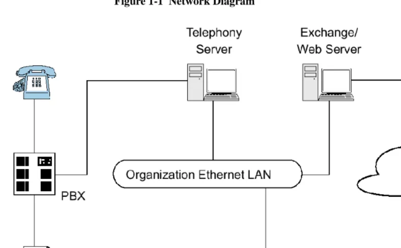
16 OnePoint Messenger/SX-200 Integration The network diagram in Figure 1-1 shows the major components that provide the unified messaging service, examples of the clients, and the relationship between the components.
Figure 1-1 Network Diagram
Telephony Server
In these guides,“Telephony Server” is used to refer to the collection of OnePoint Messenger telephony applications that reside on “the Telephony Server” (the computer running the Windows NT Server 4.0 operating system).
The OnePoint Messenger software on the Telephony Server is com-prised of a group of Windows NT Server applications that, among other tasks, provide the link between the SX-200 and Microsoft Exchange.
Those telephone call routing and messaging services include:
• Controlling what happens to calls that are not answered and pro-viding the caller the ability to leave and retrieve voice messages
What Is OnePoint Messenger and Unified Messaging? 17 accounts, and also reverse transcoding of messages saved on Exchange back to callers and VPIM accounts
• Enabling OnePoint Messenger subscribers (“users”) to retrieve and reply to e-mail messages that are read to them using the text-to-speech (TTS) capabilities of Telephony Server
• Providing advanced fax handling features, including routing e-mail to fax machines and a Fax on Demand service; see Chapter 4 of the OnePoint Messenger Administrator Guide for a discussion of OnePoint Messenger fax features.
For more on the RAS (support) programs, see the OnePoint Messen-ger Administrator Guide, Chapter 1 and Chapters 5 through 9. See Chapter 5 in that guide for operational details.
Telephony Server Peripherals
The backplane of the Telephony Server contains an Ethernet LAN card for communication with Exchange and the telephony “line cards” cards that provide the connection to the switch.
When integrating with an SX-200 switch, the Telephony Server con-tains a TalkTo CX card and one or more Natural MicroSystems (NMS) line cards in the ISA bus (also, optionally, a Brooktrout fax card). The connection to the SX-200 PBX is through both the TalkTo and NMS cards. A digital line connects the Line port on the TalkTo card to the DNIC card on the PBX. Analog lines connect the ONS card on the PBX to four duplexed RJ-61 ports on each NMS AG-8 card.
For details on installing the TalkTo card in the TS800 turnkey Tele-phony Server, see Chapter 3 (page 39). See Appendix A of the OneP-oint Messenger Getting Started Guide for recommendations on card arrangement in ISA slots (“slot map”), and IRQ and I/O base address assignment.
For an overview of installing other line cards, see Appendix B in the OnePoint Messenger Installation Guide, then see the manufacturer documentation.
18 OnePoint Messenger/SX-200 Integration
Benefits of the Integration
The integration between the PBX and the Telephony Server provides these benefits:
• Forward to Personal Greeting: Provides the ability to play a user’s personal greeting to a caller who has been forwarded to voice mail.
• Auto Logon: The Telephony Server can recognize a caller as a OnePoint Messenger subscriber (“user”), rather than as an outside caller, when calling directly from the user’s phone. The Tele-phony Server greets users by name and asks for their passcodes.
• Multiple Use Ports: Allows use of the same port for dynamic allocation of ports for the Automated Attendant, the Message Center, including Text-to-Speech e-mail access, or fax services.
• Direct Answer to Internal Message: Allows a message recipient to record an answer to a message from another user without hav-ing to first dial the user’s extension.
• Message Notification: Allows the Telephony Server to send a message waiting notification to a user through the PBX. The PBX then activates the message waiting indicator, such as a light or a stutter dial tone, on the user’s extension.
Call Flow Overview
This is a basic overview of the processing sequence of calls routed from the SX-200 PBX to the Telephony Server:
1. The PBX receives a call intended for an extension managed by the PBX.
2. If the call is to a OnePoint Messenger user whose phone is busy or is not answered, the PBX redirects the call to the Telephony Server. The PBX also directs calls to the Telephony Server that are forwarded by users to voice mail, or users who make a direct call to the Message Center (the mailbox access pilot number) on the Telephony Server.
Call Flow Overview 19 3. The call arrives at the Telephony Server in two streams of data:
• The call itself goes to a port on the NMS card. The card has four physical ports, each of which handles two loop start phone lines.
• The calling data goes to the TalkTo card. This includes the caller’s phone number, called party’s phone number, and the reason code why the call was sent to the Telephony Server; this is also known as CLI, or calling line identification.
4. The NMS card detects the call and alerts Telephony Server. At the same time, the TalkTo card passes the CLI data to Telephony Server software that uses the called number to determine whether to play a system greeting or a user’s greeting. The TalkTo card’s role is complete for this call.
5. Telephony Server maintains a cache of user profile information, including digitized greetings. The appropriate greeting loads from the Telephony Server onto the NMS card, which converts it to analog speech and plays it to the caller.
6. The Telephone User Interface (TUI) on the Telephony Server sends the appropriate digitized prompts to the NMS card for con-version and playing to the caller. For example, if the call is for a user, the TUI prompts the caller with the messaging options avail-able, such as to record or re-record a voice message, or to leave a fax.
7. The caller responds with a voice message or keypad input.
8. The NMS card converts the analog input from the caller (the voice message and keyed responses to prompts) into digital strings for Telephony Server. The NMS card routes fax messages through the Brooktrout card.
9. Telephony Server packages the caller’s message into a digital file and routes it to the recipient’s mailbox on the Exchange Server.
20 OnePoint Messenger/SX-200 Integration
Task Overview
1. Install ONS and DNIC digital line cards on the SX-200 PBX, then configure the PBX to communicate with the Telephony Server. See Chapter 2 (page 23).
2. Install and configure the TalkTo card on the Telephony Server. See Chapter 3 (page 39).
3. Install and configure the NMS AG-8 cards and Brooktrout card on the Telephony Server. See the manufacturers’ documentation and Appendix B in the OnePoint Messenger Installation Guide.
4. Install the MiTAI 7.5.3 software on the Telephony Server, then configure MiTAI for the TalkTo card and the SX-200. See Chap-ter 4 (page 47).
5. Install the OnePoint Messenger software on the Telephony Server. See Chapter 6 in the OnePoint Messenger Installation Guide.
6. Configure Show N Tel and the other Telephony Server software to communicate with the PBX. See Chapter 5 (page 55).
Integration Strategy
OnePoint Messenger provides three services that you can set up so that callers can access any one of them by dialing unique pilot num-bers. They are Automated Attendant (automated receptionist), Mes-sage Center (access to mailboxes), and Fax on Demand (faxback). Typically, to be able to provide optimum access to each service, you would create a hunt group for each, the total lines of which would match the number of lines attached to the Telephony Server assigned to incoming calls. For the SX-200 integration, however, you must route calls to the Automated Attendant and Fax on Demand through the Message Center pilot. Chapter 2 (page 23) here describes creating subscriber extensions for Automated Attendant and Fax on Demand (often called phantom extensions), set up to forward all calls to the Message Center pilot.
Integration Strategy 21 dialed services (Automated Attendant, Message Center, and Fax on Demand). The correct service answers based on the pilot number that the caller dials.
OnePoint Messenger/SX-200 Integration Guide, Rev. A, 8/9/00 23
2. Configuring the SX-200 PBX
This chapter contains required PBX settings to enable OnePoint Mes-senger unified messaging. This chapter contains these sections:
For details on SX-200 programming procedures, see your Mitel docu-mentation:
• For details on data entry, refer to the Mitel Practice, SX-200 PBX Customer Data Entry (CDE) (91xx-yyy-210, where xx is the product designator and yyy is the software release).
• For specific information on ONS voice mail setup, see the docu-ment SX-200 EL-ML Technical Documentation–Release 3.1.
Section Page
Required Forms and Settings 25
Form 1, System Configuration 26
Form 2, Feature Access Codes 26
Form 3, COS Definitions 26
Form 4, System Options 29
Form 9, Desktop Device Assignments 30
Form 11, Data Circuit Descriptors 30
Form 12, Data Assignment 31
Form 17, Hunt Group 31
Form 31, System Abbreviated Dial Entry 31
Form 34, Direct I/O 33
24 Chapter 2, Configuring the SX-200 PBX • On the Mitel SX-200 EL/ML LIGHTWARE 17 CD-ROM (P/N
9109-953-081-NA), refer to the section “Voice Mail on ONS Ports”.
CAUTION! Only a Mitel-certified SX-200 PBX technician should program the SX-200.
Information exchange between the Telephony Server and the SX-200 PBX is achieved through the Mitel Application Interface (MAI), of which MiTAI is a component. To accommodate the MAI link, the PBX should contain the following hardware:
• DNIC digital line circuit for the TalkTo card connection
• ONS card for analog voice mail ports on the NMS cards
Program the PBX for MAI operation. You can program only one MAI port for the PBX system.
NOTE: You can program the MAI link without removing the PBX from service.
Overview of OnePoint Messenger Requirements
From the viewpoint of programming the PBX, the OnePoint Messen-ger unified messaging system provides two general categories of fea-tures:
• Message Center, Automated Attendant, and Fax on Demand
• Message Waiting notifications and fax forwarding
Message Center, Automated Attendant, and Fax on Demand are grouped together, because they can use the same incoming lines and trunks. Each needs its own pilot number. Note that the SX-200 can have its own Automated Attendant; it is as an optional feature. There are several ways that you can set up support for Automated Attendant and Fax on Demand on the SX-200. The simplest way is to program dedicated extensions that are permanently rerouted to the voice mail access code.
Required Forms and Settings 25 For the OnePoint Messenger installer, make a written record of the line numbers that you enable for OnePoint Messenger, their functions (Message Center, Message Waiting Indicator, etc.) and pilot numbers.
Required Forms and Settings
Programming the MAI port consists of entering data in the Customer Data Entry forms on the PBX that are listed here:
• Form 1, System Configuration (See page 26 and Figure 2-2 on
page 34.)
• Form 2, Feature Access Codes (See page 26 and Figure 2-3 on
page 35.)
• Form 3, Class Of Service (See page 26 and Figure 2-4 on
page 35.)
• Form 4, System Options/System Timers (See page 29 and Figure 2-5 on page 36.)
• Form 9, Desktop Device Assignments (See page 30 and Figure 2-5 on page 36)
• Form 11, Data Circuit Descriptors (See page 30 and Figure 2-6 on
page 36.)
• Form 12, Data Assignment (See page 31 and Figure 2-7 on
page 37.)
• Form 17, Hunt Groups (See page 31 and Figure 2-8 on page 37.)
• Form 31, System Abbreviated Dial Entry (See page 31 and Fig-ure 2-9 on page 38.)
• Form 34, Direct I/O (See page 33 and Figure 2-10 on page 38.)
The following sections list the required settings that enable the OneP-oint Messenger integration.
Examples of the forms appear in the section “Examples of the Cus-tomer Data Entry (CDE) Forms” on page 34. You can program the forms generally in numerical order, except that Mitel recommends that you program Form 12 before Form 11 so that the “# of Data Cir-cuits Assigned” field in Form 11 will be automatically set correctly and be read-only.
26 Chapter 2, Configuring the SX-200 PBX
Form 1, System Configuration
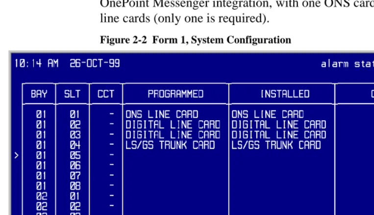
Use Form 1 (see Figure 2-2, page 34) to identify the location by bay, slot, and circuit of the DNIC and ONS cards in the PBX.
NOTE: While you only use one digital line card for the TalkTo con-nection, you may install more than one digital line card in the PBX for other purposes.
Form 2, Feature Access Codes
Use Form 2 (see Figure 2-3, page 35) to identify the access codes for the necessary features, as listed in Table 2-1.
NOTE: The numbers in the Access Code field are examples only.
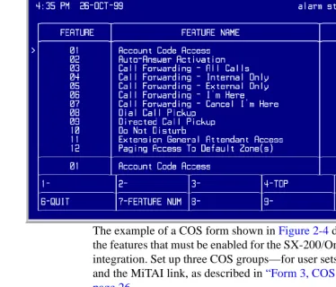
Form 3, COS Definitions
Use Form 3 (see Figure 2-4, page 35) to create five classes of service:
• User sets
• ONS voice mail ports
• MiTAI link
• Message Waiting/Pager notification
• Trunk (optional): A Trunk COS impacts the forwarding of exter-nal calls to voice mail. Enable COS Option 208 in the trunk COS.
Not all of the COS features listed below are required, but they are compatible with the integration while providing upgradeability. Refer to SX-200 Customer Data Entry (91xx-yyy-210-NA) for further information. On the Mitel SX-200 EL/ML LIGHTWARE 17
CD-Table 2-1 Form 2, Required Feature Access Codes
Feature Number Feature Name Access Code
03 Call Forward - All Calls *70
04 Call Forward - Internal Only *71
05 Call Forward - External *72
41 Send Message *4
30 Last Number Redial *50
Required Forms and Settings 27 ROM (P/N 9109-953-081-NA), refer to the section “Voice Mail on ONS Ports”.
Table 2-2 shows the required features common to all four classes of service.
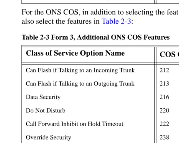
For the ONS COS, in addition to selecting the features in Table 2-2, also select the features in Table 2-3:
Table 2-3 Form 3, Additional ONS COS Features
For the COS of the user stations, in addition to selecting the features in Table 2-2, also select the features in Table 2-4:
Table 2-2 Form 3, COS Features Common to the Four COS Groups
Class of Service Option Name COS Option Number
Call Forwarding - Busy 206
Call Forwarding - Don’t Answer 207
Call Forwarding - External 208
Call Forwarding - Follow Me 209
Message Waiting Setup - Lamp 232
SUPERSET Tel. - Message Program 605
Class of Service Option Name COS Option Number
Can Flash if Talking to an Incoming Trunk 212
Can Flash if Talking to an Outgoing Trunk 213
Data Security 216
Do Not Disturb 220
Call Forward Inhibit on Hold Timeout 222
Override Security 238
Line Privacy 240
Abbreviated Dialing Access 245
ONS Voice Mail Port 261
Camp-On 301
28 Chapter 2, Configuring the SX-200 PBX
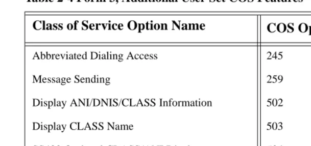
Table 2-4 Form 3, Additional User Set COS Features
For the MiTAI link COS, in addition to selecting the features in Table 2-2, also select the features in Table 2-5:
Table 2-5 Form 3, Additional MiTAI link/DNIC 2103 COS Features
For the Message Waiting/Pager Notification COS, in addition to selecting the features in Table 2-2, select the features in Table 2-6:
Table 2-6 Form 3, Additional MWI/Pager Notification COS Features
Class of Service Option Name COS Option Number
Abbreviated Dialing Access 245
Message Sending 259
Display ANI/DNIS/CLASS Information 502
Display CLASS Name 503
SS420 Optional CLASS/ANI Display 504
PBX Superset Tel. - Automatic Outgoing Line 604
Class of Service Option Name COS Option Number
Call Hold and Retrieve Access 211
Can Flash if Talking to an Incoming Trunk 212
Can Flash if Talking to an Outgoing Trunk 213
Line Privacy 240
Display Prime as Forwarder 258
Camp-On 301
PBX Superset Tel. - Automatic Outgoing Line 604
Class of Service Option Name COS Option Number
Data Security 216
Do Not Disturb 220
Originate Only 235
Override Security 238
Required Forms and Settings 29 NOTE: Voice Mail System Speed Dial Index (0-255) in Table 2-6: This option applies to ONS voice mail port hunt groups. When enabled, this option identifies a set/station that is accessing voice mail through the message waiting key to retrieve messages. The user lis-tening to messages can also use the Messaging - Call Me Back feature to reply to messages. This COS option is disabled by default. To enable, assign an index number from 0 to 255. This index number will point to an abbreviated dial entry in Form 31.
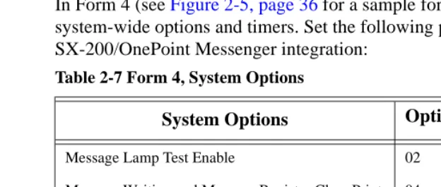
Form 4, System Options
In Form 4 (see Figure 2-5, page 36 for a sample form), specify the system-wide options and timers. Set the following parameters for the SX-200/OnePoint Messenger integration:
Disable option number 22, Last Party Clear - Dial Tone. This will avoid having a dial tone from a premature hangup be recorded as a message.
NOTE: If you use Mitel 4000 series telephones, enable option 112, SS4000 Series Sets.
ONS Voice Mail Port 261
Voice Mail System Speed Dial Index 0 - 255 265
Camp-On 301
Class of Service Option Name COS Option Number
Table 2-7 Form 4, System Options
System Options Option Number
Message Lamp Test Enable 02
Message Waiting and Message Register Clear Print 04
Incoming to Outgoing Call Forward 21
Maximum BNIC Cards 110
Mitel Application Interface Use 19 for SX-200 EL,
30 Chapter 2, Configuring the SX-200 PBX
Form 9, Desktop Device Assignments
Use Form 9 to assign the COS that you defined in the COS form for user sets (see “Form 3, COS Definitions” on page 26") to each exten-sion served by OnePoint Messenger.
1. In the Extension field of the form, enter an extension for a user set served by OnePoint Messenger.
2. In the COS field for that extension, enter the number of the COS defined for user sets to be ONS-enabled.
3. In the COR field for that extension, accept the default of 1.
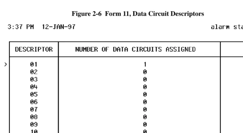
Form 11, Data Circuit Descriptors
Use Form 11 (see Figure 2-6, page 36 for a sample form) to set up a data circuit descriptor for the MAI port.
NOTE: Mitel recommends that, for the OnePoint Messenger integra-tion to the SX-200, you complete this form after Form 12. In that case, in the Descriptor field equivalent to the descriptor number that you choose for the MAI port, the number “1” will automatically appear in the Number of Data Circuits Assigned field. Add “TalkTo/ MiTAI” in its Comment field.
For the new MAI port descriptor number, choose Select Option, then set the parameters to the values shown in the table below, or select an existing descriptor number that has parameters set as shown below.
Table 2-8 Form 11, Data Circuit Descriptor, Select Option
Parameter Name Value
SYNC: Operating Mode SYNCHRONOUS
SYNC: Rate Adaption Scheme X.31
SYNC: Clock Source SYSTEM
MAXIMUM BAUD RATE 19200
Default Baud Rate 19200
Required Forms and Settings 31
Form 12, Data Assignment
Use Form 12 (see Figure 2-7 on page 37 for a sample form) to pro-gram the MAI port (MiTAI link) for the dataset.
1. In the Bay, SLT, and CCT fields, verify the bay, slot, and circuit numbers of the DNIC card, then enter DS2103 in the Type field to program a Dataset 2103 dataset unit as the device type for the MAI circuit on the digital line card that you programmed in Form 1 (page 26).
2. Assign an extension number (EXT NUM field), MiTAI link class of service number (COS field, from Form 3, page 26), and class of restriction number (COR field) for the dataset.
3. Assign the Data Circuit Descriptor Number in the CDN field. The Number of Data Circuits Assigned column on Form 11 will then display a 1 next to the descriptor number that you assign here.
NOTE: The tenant number you put in the TEN field must be the same in all forms that reference the tenant number.
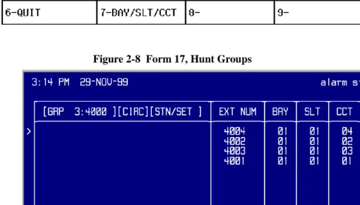
Form 17, Hunt Group
Use Form 17 (see Figure 2-8 on page 37 for a sample form) to create a circular hunt group for the extensions accessing the Telephony Server, with the message center number as the pilot number of the hunt group.
To set the Message Center pilot number:
Select Access Code (option 7) at the bottom of the form, then enter the pilot number to be used for the OnePoint Messenger Message Center.
NOTE: Note the pilot number for entering on the Telephony Server in the Telsrver.ini file and the System Parameters tab in Telephony Server Administrator. See the section “Setting OnePoint System Parameters” on page 67 in Chapter 5 for instructions on entering the pilot number on the Telephony Server.
Form 31, System Abbreviated Dial Entry
32 Chapter 2, Configuring the SX-200 PBX of voice mail messages. The integration of the PBX and voice mail system is based on the abbreviated dial numbers shown below.
NOTE: For an explanation of the timing requirements, see Form 31 on the “SX-200 EL/ML Technical Documentation” Mitel Folio CD-ROM. On the equivalent Mitel Documentation Web page, use this path: Program Features, Voice Mail Support, Voice Mail on ONS Ports
Set up the desired call forwarding for the telephones using this voice mail feature.
• Place all ONS voice mail ports in the same hunt group in Form 17 (see page 31). Assign an access code to the group.
• For trunk calls to reach the ONS voice mail system via a forward-ing system abbreviated dial number, enable System Option 21 (Incoming to Outgoing Call Forward) and COS Option 208 in the trunk COS.
For Message Forward:
1. Enter an index number for message forward in the INDEX NUM-BER field of Form 31, System Abbreviated Dial Entry.
2. Enter in the DIGIT STRING field:
• The ONS voice mail hunt group access code
• *6
Table 2-9 Form 31, System Abbreviated Dial Entry
Code Description
*1 5 second pause
*3 XX Insert manual dialed digits (XX) 2 digits expected
*6 Tone out caller extension number
*9 1 second pause
** DTMF digit
# DTMF digit #
Check MAI Installation and Programming 33
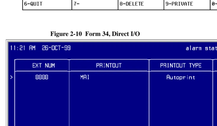
Form 34, Direct I/O
Use Form 34 (see Figure 2-10 on page 38 for a sample form) to enter the extension number of the MAI port. Enter the same extension num-ber that you assigned to the Dataset 2103 dataset unit in Form 12 (page 31).
1. Enter the extension number of the MAI port.
2. Program the Printout, Printout Type, and Guaranteed fields as shown in Table 2-10.
Check MAI Installation and Programming
After installing the physical link from the PC to the PBX, check:
• DNIC line card is installed and programmed correctly
• MAI programming is correct
Show Status Command
Use the Show Status command in the SX-200 Maintenance facility to check the status of the installation and commissioning. The Show Sta-tus command displays the current call processing or maintenance state of the devices that are connected to a PBX circuit card. Deter-mine the status of a device by its bay/slot/circuit number or extension number. An example of the display is shown in Figure 2-1.
Figure 2-1 Show Status Command Display
Table 2-10 Form 34, MAI Programming: Direct I/O
Parameter Name Value
Ext Num 1802 (for example)
Printout MAI
Printout Type AUTOPRINT
34 Chapter 2, Configuring the SX-200 PBX If the MAI link is up and running, the SWSTAT field shows TALKG. If the link is not operating, the SWSTAT field shows IDLE.
Examples of the Customer Data Entry (CDE) Forms
Some examples of the forms shown here are from the Mitel SX-200 EL/ML & LIGHT CD-ROM and are shown only for illustrating the layout of the forms. Those examples, which have a white background, do not necessarily show the values that should be entered to enable the connection to the Telephony Server.
Figure 2-2 shows Form 1, System Configuration, from an SX-200/ OnePoint Messenger integration, with one ONS card and two digital line cards (only one is required).
Figure 2-2 Form 1, System Configuration
Examples of the Customer Data Entry (CDE) Forms 35
Figure 2-3 Form 2, Feature Access Codes
The example of a COS form shown in Figure 2-4 does not show all the features that must be enabled for the SX-200/OnePoint Messenger integration. Set up three COS groups—for user sets, voice mail ports, and the MiTAI link, as described in “Form 3, COS Definitions” on page 26.
36 Chapter 2, Configuring the SX-200 PBX
Figure 2-5 Form 4, System Options/System Timers
Examples of the Customer Data Entry (CDE) Forms 37
Figure 2-7 Form 12, Data Assignment
38 Chapter 2, Configuring the SX-200 PBX
Figure 2-9 Form 31, System Abbreviated Dial Entry
Figure 2-10 Form 34, Direct I/O
OnePoint Messenger/SX-200 Integration Guide, Rev. A, 8/9/00 39
3. Installing the TalkTo Card
This chapter provides information about installing the TalkTo card in the OnePoint Messenger Telephony Server. If your Telephony Server already has the TalkTo card installed, you can skip this chapter.
For information on installing other line cards in the Telephony Server, including Mitel AFC, Natural MicroSystems (NMS), and Brooktrout fax cards, see Appendix B in the OnePoint Messenger Installation Guide. See Appendix A of the OnePoint Messenger Get-ting Started Guide for recommendations on card arrangement in ISA slots (“slot map”), and IRQ and I/O base address assignment.
This chapter contains these sections:
About the TalkTo CX Card
The TalkTo CX card, shown in Figure 3-3, is a Mitel card that you install in an ISA slot in the Telephony Server. The TalkTo card receives the calling line identification data (CLI, or “D-channel”) from the Mitel SX-200, and passes the data through the ISA bus on the Telephony Server to the Mitel Telephony Application Interface (MiTAI). MiTAI associates the CLI with the Telephony Server port that carries the incoming call. The TalkTo card also transfers Mes-sage Waiting alerts from the Telephony Server to mesMes-sage recipients’ extensions through the PBX. The TalkTo card communicates with the PBX through RJ-11 twisted pair wires from the 6-lead RJ-14 jack
Section Page
40 Installing the TalkTo Card labelled “Line” at the top of its connecting bracket. The connection on the PBX is a port on the DNIC digital line card. The cable connec-tion is generally through a patch panel.
SX-200 Support for Peripherals
The SX-200 supports one HCI link and a maximum of 200 monitors. The DNIC connection to a TalkTo CX card is the only connection supported on the SX-200. Fiber connectivity is not supported to the TalkTo card.
The TalkTo card does not have an MVIP connector on it and does not connect directly to the other cards on the Telephony Server.
Installing the TalkTo Card
TalkTo CX card installation consists of the following tasks in this suggested order:
1. If required by conflicts with other cards in the Telephony Server, change the TalkTo CX card IRQ (default = 15) or I/O base address (default = 0300h) and edit the System.ini file, as described below in “Changing the IRQ” on page 44. See a dia-gram of the TalkTo card in Figure 3-3 for alternative IRQ and address locations.
To check current IRQ and base addresses:
a. From the Windows Start button, choose Programs, then Administrative Tools, Windows NT Diagnostics, and Resources
Installing the TalkTo Card 41
Figure 3-1 Windows NT Diagnostics, Resources Tab, IRQ List
Figure 3-1 displays the IRQ table from a TS800 Telephony Server integrated with an SX-200:
• IRQ 7 (07) in the IRQ resource list is assigned to “Aghw,” the NMS AG-8 card.
• IRQ 9 is assigned to the TalkTo card.
• IRQ 15 is assigned to the ATAPI interface. Since IRQ 15 is the TalkTo card default IRQ, it would be necessary to change the TalkTo card IRQ.
NOTE: Windows NT Diagnostics sometimes does not display all settings, so, after you shut down and install the TalkTo card, it is wise to check settings in CMOS at bootup.
42 Installing the TalkTo Card
Figure 3-2 Windows NT Diagnostics, I/O Port List
NOTE: If you are also installing NMS line cards and Brooktrout fax cards, also note available IRQ and I/O address resources for those cards while you view the Resources tab. Multiple Brook-trout cards can share an IRQ, and multiple NMS cards can share another IRQ.
d. To close Windows NT Diagnostics, click OK.
2. Install the TalkTo CX card in an ISA slot in your PC. If you are using the TS800 Telephony Server, see Appendix A of the Get-ting Started Guide for recommended slot, IRQ, and I/O address assignments.
The TalkTo CX card does not have an MVIP connector, so you should install the TalkTo card in a slot at either end of the row of cards NMS and fax cards that are connected together with an MVIP cable.
Since the TalkTo card does not connect to the other cards, the ports on the NMS card must be connected through twisted pair cabling directly to the ONS card on the SX-200 PBX.
Troubleshooting the TalkTo Card Installation 43 PBX. The NMS card uses it as a resource through the MVIP cable.
3. The PBX to which the PC will be connected must be pro-grammed, as discussed in Chapter 2 (page 23).
4. Install and configure the Mitel MiTAI software, as discussed in Chapter 4 (page 47) of this guide. Also use the MiTAI interface to note IRQ and memory conflicts.
TalkTo CX Card Configuration
Refer to the printed TalkTo CX card installation manual included with your card for detailed instructions on how to configure and install your card. Basically, the installation consists of revising the IRQ and I/O base address, if necessary.
TalkTo CX Card Settings
The TalkTo CX card is factory-configured with these settings:
• IRQ = 15 (the TalkTo factory-installed on the TS800 is set to 9)
• I/O base address = 0300h
Troubleshooting the TalkTo Card Installation
If the TalkTo CX card or another card in the Telephony Server does not respond, check your current system configuration and the NT Event Viewer. You can change either the TalkTo card settings, or you may be able to change those of another card. Make sure that the phys-ical IRQ jumper settings on the TalkTo card correspond to the IRQ value shown in the System.ini file, as described below in “Changing the IRQ” on page 44.
You can use any of the following techniques to determine your sys-tem configuration:
• System BIOS settings: PC motherboards allow you to configure parameters relevant to the system. Some systems will use the BIOS to configure serial (COM) and parallel (LPT) ports.
• Jumper/Switch settings on the cards: Some peripheral cards (such as the TalkTo CX) have jumpers that set the system param-eters such as IRQ, I/O base address, RAM base address, etc. See
44
details on how the parameter values relate to the jumper/switch settings of the relevant peripheral cards.
• MSD (Microsoft Diagnostic): Microsoft Windows includes MSD.EXE (usually located in \windows\system directory) that provides information about IRQ status, i.e., IRQs that are already in use, I/O base addresses for the COM and LPT ports (note that not all IRQs in use are necessarily shown with MSD.)
MSD.EXE is best used from DOS (not from a DOS window or DOS running full screen in Windows, but rather from DOS before starting Windows).
• Software provided by the peripheral card manufacturer: Some peripherals have setup/diagnostic software that reports or tests their settings.
Changing the IRQ
The possible IRQ level settings for the TalkTo CX are 3 through 7, 9 through 12, 14, and 15. The IRQ jumper block on the TalkTo card, as shown in Figure 3-3, has jumpers for each of those numbers and no others. There is a label on the card above the jumper block showing the IRQs above each pin; 15 is at the left end.
To configure the system with a new IRQ on the TalkTo card:
1. Find an unused IRQ in Windows Diagnostics, as described above in “Installing the TalkTo Card” on page 40.
NOTE: On the TS800, reserve the IRQ in the BIOS. To do this, press F2 during system reboot to start the BIOS Setup Utility. On the Advanced screen, select Resources Configuration. If the IRQ you want to use is not already reserved, select it, then press Enter, then select Reserved.
2. Edit the Dnic sectionof the System.ini file in the Windows directory to change the entry IRQ = 15 to the new value.
3. Save the new System.ini file.
4. Shut down the system.
5. Set the new value on the TalkTo card IRQ jumper block, as indi-cated in the TalkTo card installation manual. See the TalkTo card in Figure 3-3, below.
Troubleshooting the TalkTo Card Installation 45 7. Start Windows.
8. In MiTAI (see “Installing MiTAI on the Telephony Server” on page 47 in Chapter 4), set the IRQ to the same value.
Changing the I/O Base Address
The possible I/O base address settings are 200h, 220h, 240h, 260h, 300h, 320h, 340h, 360h.
To change the default of 0300h to another:
1. Remove the appropriate jumper(s) from the base address jumper block on the TalkTo card, as listed in Table 3-1. The letters A through F appear from left to right above the address jumper block on the TalkTo card, as shown in Figure 3-3.
2. In MiTAI (see “Installing MiTAI on the Telephony Server” on page 47 in Chapter 4), set the base address to the same value as you chose here.
NOTE: The card is auto-detected by the driver at initialization.
Figure 3-3 TalkTo Card Diagram
IRQ Select Address Select
1514121110976543TERM
M5024
End View of Card
VOICE LINE
IRQ SELECT
ADDR SELECT
W1 W2 W3 W4
46 Installing the TalkTo Card
Table 3-1 Base Address Locations on the TalkTo Card
Base Address
Pins
A B C D E F
200h ON ON ON ON ON ON
220h ON ON ON ON ON off
240h ON ON ON ON off ON
260h ON ON ON ON off off
300h ON ON ON off ON ON
320h ON ON ON off ON off
340h ON ON ON off off ON
OnePoint Messenger/SX-200 Integration Guide, Rev. A, 8/9/00 47
4. Installing Mitel Telephony
Application Interface (MiTAI)
This chapter contains instructions for installing and configuring the Mitel Telephony Application Interface 7.5.3 (MiTAI 7.5.3) software on the OnePoint Messenger Telephony Server. MiTAI helps establish communications between the Telephony Server and the SX-200 through a TalkTo card. This chapter contains the procedures for installing and configuring MiTAI on the Telephony Server for an SX-200/TalkTo integration.
What You Need to Complete this Chapter
To complete the installation detailed in this chapter, you will need the following:
• The Mitel TalkTo card installed in the Telephony Server and con-nected to the PBX
• The PBX running and configured for OnePoint Messenger
• Mitel MiTAI 7.5.3 CD-ROM
• MiTAI license
Installing MiTAI on the Telephony Server
Installing MiTAI on the Telephony Server
1. If you are installing MiTAI 7.5.3 in a system that has a version of MiTAI installed, you must first uninstall that existing version. Use the Uninstall MiTAI program if there is one in the MiTAI
Section Page
48 Chapter 4, Installing Mitel Telephony Application Interface (MiTAI) program group. If not, remove the program by using the Add/ Remove Programs applet in the Windows Control Panel.
2. Insert the Mitel MiTAI Toolkit CD-ROM into the CD-ROM drive of the Telephony Server (alternatively, download the soft-ware to your hard drive from the Mitel website.) If the CD-ROM auto-run is enabled on your Telephony Server, the software installation routine will start when you insert the CD-ROM.
If auto-run is not enabled, use the Run dialog in your Windows Start menu or use Windows Explorer to locate the
\runlocal\Windows NT directory on the CD-ROM. In this direc-tory, invoke Setup.exe.
3. On the Select the MiTAI Runtime required for your PC dia-log, click OK to accept the MiTAI Local Runtime default.
If you used Windows Explorer to launch Setup, you do not see this screen.
4. Accept the defaults for the next three screens:
• Welcome
• MiTAI Runtime Software License Agreement
• System Information (The screen should note that Windows NT 4.0 with Service Pack 5 is installed.)
5. On the Initialize the MiTAI Settings screen, click the Default Settings radio button, then click Next.
6. On the Destination Location screen, click Next to accept the default of Program Files/Mitel/MiTAI)
7. On the Initialize Settings screen, select [TBD], then click Next.
8. On the Program Folder screen, click Next to accept the default program group name of Mitel Telephony Application Interface.
9. On the Start Copying Files screen, click Next. Progress bars appear to monitor the status of the installation as the software loads.
Installing MiTAI on the Telephony Server 49
Figure 4-1 MiTAI Settings Dialog, Hardware Tab
11. On the Hardware tab:
• IRQ—Click the Interrupt drop-down arrow to select the IRQ that you set on the TalkTo card, as described in “Chang-ing the IRQ” on page 44 in Chapter 3. The TalkTo default IRQ is 15. The TS-800 turnkey system uses 11.
Figure 4-1 shows the MiTAI default IRQ of 9, with a note in the Hardware Conflict Report area that there are no conflicts with IRQ = 9. If you change the value, note whether no con-flict is reported.
• Base Address—Click the I/O Address drop-down arrow to select the I/O Address that you set on the board, as described in “Changing the I/O Base Address” on page 45 in Chapter 3. The default of A300 appears in Figure 4-1.
• Click Apply.
50 Chapter 4, Installing Mitel Telephony Application Interface (MiTAI)
Figure 4-2 MiTAI Settings Dialog, Software Tab
13. On the Software tab:
a. Click Start. A progress bar activates at the bottom of the screen, and the red indicators begin to change to green, start-ing from the top.
b. The bottom “Telephony Link is Up” indicator can take sev-eral minutes to turn green. When it turns green, click OK.
c. If the progress bar repeats, make sure the link between the TalkTo card and the PBX is connected. If the installation sequence does not complete, click Cancel, remove the soft-ware, reboot, and reinstall, making sure that the connection to the PBX is secure.
Checking the Operation of the MiTAI Link to the PBX 51
Figure 4-3 MiTAI Settings Dialog, Versions Tab
You can open the MiTAI Settings dialog to view or edit settings on the tabs above by double-clicking the MiTAI icon in the Windows Control Panel.
Checking the Operation of the MiTAI Link to the PBX
1. From the Windows Start menu, choose Programs, then MITAI Runtime, then MITAIX. MITAIX appears in a DOS window with a “phoneset to monitor” prompt.
2. Type the extension of any valid phone in the system that has Class of Service options set for HCI monitor (see “Form 3, COS Definitions” on page 26). Press Return.
3. A “connect:” prompt appears if the phone is valid. At the base of the window, enter:
makecall <extension number>
Press Enter.
4. If the phone at the selected extension rings, the MiTAI link to the PBX is working properly.
5. Quit the DOS window.
52 Chapter 4, Installing Mitel Telephony Application Interface (MiTAI) In the example in Figure 4-4, the operator entered “trunk 701" at the Phoneset(s) to monitor prompt.
Figure 4-4 MiTAIX Program Window 1
When you press Enter after entering an extension for “Phoneset to monitor”, the window shown in Figure 4-5 appears. The data in the window confirms that the PBX acknowledged the command, recog-nized the number as valid, and returned status on it.
Figure 4-5 shows that the operator entered “make 7895" at the base of the screen to request that the PBX ring the 7895 extension over the 701 trunk. Note that you should not enter the command next to the “connect” prompt.
Figure 4-5 MiTAIX Program Window 2
Editing the Server Hosts File 53
Figure 4-6 MiTAIX Program Window 3
Editing the Server Hosts File
Editing the Server Hosts file uses the same procedure as described in Chapter 4 in the OnePoint Messenger Installation Guide.
MiTAI Runtime, which is used to establish the link between the Telephony Server and the PBX, requires a listing in the Telephony Server Hosts file:
1. Open a text editor such as Windows Notepad.
2. Open the Hosts file, in \WINNT\system32\drivers\etc.
3. Read the instructions in the file header, then add an entry for MiTAI Runtime in the following form:
<IP address> <HostName> MiTAI
where <IP address> corresponds to your Telephony Server’s IP address, and <HostName> is your Telephony Server’s computer name.
OnePoint Messenger/SX-200 Integration Guide, Rev. A, 8/9/00 55
5. Configuring OnePoint
Messenger PBX Integration
Software
For the SX-200 integration, use this chapter in replace of Chapter 4 in the OnePoint Messenger Installation Guide. This chapter covers using Show N Tel Manager to identify the SX-200 and trunks assigned to voice mail, and to apply telephony applications to ports. It also discusses using the Unified Messaging Snap-in to Microsoft Management Console for assigning pilot numbers to OnePoint Mes-senger services. The final section is on starting Telephony Server.
Section Page
Introduction 56
Integrating the Telephony Server with the SX-200
• Show N Tel Telephony Applications Overview
• Notification Server Configuring and Testing Overview
56
56 57
Configuring Show N Tel with the SX-200 PBX 59 Assigning Programs to Lines 61 Modifying the Phone System Definition 63 Setting Show N Tel Parameters 66 Setting OnePoint System Parameters
• Editing the Server Hosts File
• Editing the Telsrvr.ini file for a Mitel PBX Integration
67
68 69
Starting and Stopping Telephony Server
• Configuring OnePoint Messenger to Auto-start
70
71
56 Chapter 5, Configuring OnePoint Messenger
Introduction
This chapter introduces you to the configuration of OnePoint
Messenger with an SX-200 PBX. This enables you to use telephones to communicate with Exchange through the Telephony Server. Before you perform the procedures in this chapter, you must have installed and configured your line and fax cards on the Telephony Server.
Integrating the Telephony Server with the SX-200
Integrating the PBX with the Telephony Server requires the use of the Show N Tel Manager program from Brooktrout Software, installed as part of the installation of OnePoint Messenger. Show N Tel Manager interfaces the telephony services of the Telephony Server with the PBX by configuring each port on the Telephony Server line card(s) with PBX lines and protocols. Show N Tel Manager is in the Show N Tel program group on the Telephony Server.
To accomplish integration with an SX-200, perform the procedures detailed in this chapter. For details on Show N Tel Manager, see Get-ting Started withShow N Tel and Show N Tel System Administrator Guide, both from Brooktrout and included on the OnePoint Messen-ger CD-ROM as sntgetstart.pdf and sntmgrguide.pdf, respectively.
The Unified Messaging Snap-in to Microsoft Management Console (MMC) replaces Telephony Server Administrator in this version of OnePoint Messenger as the configuration interface for the Telephony Server Telephone User Interface (TUI). During installation, it is installed with a set of defaults that allow the Telephony Server to pro-vide basic services to telephone callers after you have completed the application assignment procedures in Show N Tel. When you have successfully established communication from telephones to Exchange and communication between Exchange and desktop clients, you can tune the Telephony Server configuration using MMC. The use of MMC is detailed in Chapter 3 in the OnePoint Messenger Adminis-trator Guide.
Show N Tel Telephony Applications Overview
OnePoint Messenger provides telephony services through “telephony applications” that run through Show N Tel. The applications are:
Integrating the Telephony Server with the SX-200 57 • AutoRecep—Provides dedicated support to Automated
Atten-dant (automated receptionist) dialed service. For details on Auto-mated Attendant, see Chapter 3 in the OnePoint Messenger Administrator Guide. Automated Attendant support is also pro-vided by Telephony Server application (see below).
• Fax on Demand—Provides dedicated support to Fax on Demand (faxback) dialed service. For details on Fax on Demand, see Chapters 3 and 4 in the OnePoint Messenger Administrator Guide. Fax on Demand support is also provided by the Telephony Server application (see below).
• SendFax—Supports sending faxes to remote fax machines. Used by both Fax on Demand and by users downloading e-mail to remote fax machines.
• Message Delivery: Message Delivery supports the QuickFax fea-ture and Post Office Resiliency (caching telephone messages temporarily on the Telephony Server when Exchange is off-line, a feature that will be available in a future release). Assign Mes-sage Delivery to a Show N Tel line not associated with a physical port. By default, Message Delivery is assigned to SNT line 50.
• Telephony Server—General purpose application for mailbox access and messaging including TTS and receiving online faxes, also Automated Attendant and Fax on Demand.
• Notification Server—Several versions and functions, as described next.
Notification Server Configuring and Testing Overview
Notification Server is a telephony application that provides the fol-lowing three services through four variations in its implementation. The three services are:
• Message Waiting Indicator (MWI): If your PBX is set up to send MWI to the telephones that it manages, Notification Server can be set up to send MWI to users who receive unified messages (unified messages are telephone calls or e-mail created in a Uni-fied Message form). Notification Server can also turn off the MWI when the user has retrieved the message.
58 Chapter 5, Configuring OnePoint Messenger • Paging: If you assign permission to a user to receive notification via pager or remote telephone of the arrival of unified messages, Notification Server can be set up to send those alerts.
• Call-Me: Users can create combined telephone-computer mail-box sessions through a Notification Server port that is configured to support Call-Me.
The four versions of Notification Server are:
• Notification Server (Full): Provides the three services above
• Notification Server (CM): Dedicated to Call-Me
• Notification Server (Paging): Dedicated to paging users when they receive unified messages
• Notification Server (MWI): Dedicated to MWI. Notification Server (MWI) can be assigned to a virtual port (a Show N Tel line not associated with a physical port).
To invoke Notification Server (in summary):
1. Assign a PBX line that has a service level allowing long distance pager dialing and message delivery to the port to which you assign the Notification Server. The PBX must have the MWI fea-ture code defined. See Feafea-ture Number 41 on “Form 2, Feature Access Codes” on page 26 of Chapter 2.
2. On the PBX, assign a special hunt group number to the line sup-porting Notification Server, then enter that number in the Tel-Srvr.ini file under MWIPilotNumber (see “Editing the Telsrvr.ini file for a Mitel PBX Integration” on page 69below).
3. In the Runtime tab of Show N Tel Manager, assign Notification Server (Full), Notification Server (CM), or Notification Server (Paging) to Show N Tel lines that are associated with physical ports on your line card. The lines must have a service level that allows turning MWI on and off. See “Assigning Pro-grams to Lines” on page 61 for details. Assign Notification Server (MWI) to virtual ports, as defined above.
4. Modify the Phone System Definition in Show N Tel Manager to conform with the CTI PBX data integration. See “Modifying the Phone System Definition” on page 63 for details.