R E S E A R C H
Open Access
A downlink non-orthogonal multiple access
scheme having physical layer security
Naoto Horiike
1*, Eiji Okamoto
1*and Tetsuya Yamamoto
2Abstract
In recent years, the standardization for the fifth generation (5G) mobile communication systems has been actively discussed, and it is expected that a large number of wireless communication terminals, and beyond, in the current systems are accommodated in 5G systems. One of the steps in establishing this system is an advanced multiple access technology. In this paper, we propose a chaos non-orthogonal multiple access (C-NOMA) scheme for downlink transmission that offers high capacity allocation and secure wireless multiple access with physical layer security. In 5G systems where many terminals concurrently communicate, it is also important to ensure communication integrity for each user while maintaining large capacity communication. As a secure wireless channel-coded communication scheme, we have proposed a chaos multiple-input multiple-output (C-MIMO) scheme using the principle of chaos communication. By applying C-MIMO into a power-domain non-orthogonal multiple access transmission, we were able to demonstrate the operation and suitability of the C-NOMA configuration for handling both large capacity and physical layer security against eavesdroppers. We also demonstrated its improved performances through numerical simulations, and provided comparisons with those of conventional NOMA and chaos orthogonal frequency division multiple access schemes. In addition, we evaluated the security capability of the proposed technique based on the channel capacity of eavesdroppers and showed that secure transmission can be achieved using floating-point calculations.
Keywords:5G, Downlink, Non-orthogonal multiple access, Chaos, Physical layer security
1 Introduction
With the increasing advancement of Internet technol-ogy, and in addition to conventional physical devices such as personal computers and smartphones, all kinds of other objects around the world like household appli-ances and automobiles are being connected to the Inter-net. The number of these terminals is explosivelyrising, and according to a survey by IHS Technology, the num-ber of Internet of Things (IoT) devices as of 2016 is esti-mated to be around 17.3 billion, which is incidentally about 13% higher than the figures presented in 2015 by a similar survey. In addition, it is expected that the num-ber of IoT devices will expand to about 300 million worldwide in 2020, which is twice as much as the current figures. Wireless communication technologies are indispensable in the integration of the many existing
terminals in various places, into the same network; how-ever, at the same time, a massive surge in wireless traffic volume also presents a perplexing problem. Wireless traf-fic in 2020, along with the general adoption of smart-phones, is expected to be nearly 100 times than that in 2010. Hence, there is an increasing demand for further capacity enhancement of wireless communication sys-tems, and the fifth generation (5G) mobile communica-tion system has been rapidly developed to meet these demands [1–3]. The accommodation of mobile phones, automobiles, and IoT devices is planned for 5G scenarios. To ensure that this objective is achieved, the enhanced capabilities of the peak rate, massive connectivity, and ultra-reliable low latency will need to be actualized. Thus, 5G is expected to act as a social infrastructure in the infor-mation and communication technology (ICT) society, which will be further advanced in the future.
One of the key technologies for implementing high cap-acity allocation is an advanced multiple access scheme. In current mobile communication systems such as long-term * Correspondence:[email protected];[email protected]
1Graduate School of Engineering, Nagoya Institute of Technology, Nagoya,
Aichi, Japan
Full list of author information is available at the end of the article
evolution (LTE) and advanced LTE, the orthogonal fre-quency division multiple access (OFDMA) scheme is adopted as a downlink, in which the principle of orthog-onal frequency division multiplexing (OFDM) is applied for multiuser access [4]. In an OFDMA setup, one user is assigned to one channel in the frequency domain and user signals are densely deployed to improve the frequency effi-ciency. The system capacity can be increased in OFDMA by exploiting the multiuser diversity effect, where good channels are selectively allocated to each user. However, the orthogonal multiple access scheme cannot accommo-date the enormous amount of today’s wireless traffic, and as such, further evolution is required. Consequently, in 5G standardization, a non-orthogonal multiple access (NOMA) scheme that allows non-orthogonal frequency resource al-location and assigns multiple users to a single channel has been proposed [5,6]. In a NOMA scheme, a power domain is utilized in addition to the frequency domain for user multiplexing, and a higher system capacity than the OFDMA configuration can be obtained by allowing a mul-tiuser superimposed type of allocation for the inter-user interference.
However, in wireless communication environments where a large number of terminals exist in an assumed 5G scenario, and a large amount of information is simul-taneously exchanged, wireless security for each transmis-sion is equally important. In other words, it is important to ensure confidentiality by encryption to prevent infor-mation from leaking to third parties and eavesdroppers during wireless transmissions. In current communica-tion systems, upper layer encrypcommunica-tion protocols such as public key cryptography are mainly used. However, the enhancement of encryption properties only in the upper layer often leads to protocol complications and an in-crease in calculation complexity. Therefore, ensuring the integrity of wireless communication only in the upper layer is not desirable, but a similar approach in the phys-ical layer where the modulated signal is encrypted is also effective. The physical layer encryption can enhance se-curity protocols when it is concurrently used with the upper layer encryption, or can, otherwise, simplify the upper layer security protocol. As with regards to physical layer security schemes, we have proposed a chaos multiple-input multiple-output (C-MIMO) transmission method, which has both the functionality of encrypted modulation and channel coding, for exploiting the principle of chaos communications [7]. In this method, Gaussian modulated signals are generated from chaos signals correlated with transmission bits in a short block, and these signals are transmitted by MIMO spatial mul-tiplexing. A chaos signal is irregular and unpredictable, but its behavior is deterministically controlled by the ini-tial chaos value. By taking advantage of this feature, the initial chaos value can be used as a signal key shared by
the transmitter and receiver in the C-MIMO system, thereby achieving the physical layer encryption effect based on common key encryption. In essence, only a valid user at the receiver end who has the same signal key used in the transmitter can correctly decode the received sig-nals, thus blocking out third party intrusions. In addition, C-MIMO has a channel coding effect at a coding rate of 1 by convoluting the transmission bit to the chaos signal in generating the transmission signal. Thus, C-MIMO can provide secure and high-quality wireless transmission. However, C-MIMO is a link transmission scheme, and has not been applied for high-capacity allocation multiple ac-cess technologies such as 5G.
and (3) channel coding effect is effectively obtained. Thus, the proposed C-NOMA scheme can provide se-cure and very reliable transmission in cellular environ-ments assumed in 5G. We demonstrated the improved performance of the C-NOMA configuration via numer-ical simulations and compared them to those of con-ventional unencrypted NOMA and chaos OFDMA (C-OFDMA) encrypted schemes [15]. It is shown also that the coding gain and physical layer security effect can be obtained without degradation of transmission ef-ficiency in the proposed method for conventional unen-crypted NOMA scheme. Furthermore, the maximum throughput increases in the proposed technique com-pared to the conventional C-OFDMA setup. The secur-ity properties for ensuring secure connections against eavesdroppers are also evaluated for the C-NOMA scheme based on the equivalent channel capacity of an eavesdropper.
This paper is organized as follows: in Section 2, the system model of a downlink chaos NOMA scheme is de-scribed, and the chaos modulation, demodulation, and NOMA user scheduling in the proposed system are ex-plained. Section 3 presents the numerical results and performance comparisons for conventional schemes. Fi-nally, conclusive remarks are given in Section4.
(Comments #3–5) Notations: in the following section, lowercase and uppercase boldface letters denote vectors and matrices, respectively.
2 Proposed downlink chaos NOMA system
In the proposed scheme, we assume a downlink NOMA transmission system from base station (BS) to each user equipment (UE) in a single-cell environment, in which transmission signals are superimposed in the power do-main. Additional file 1: Figure S1 shows the system model of the downlink NOMA scheme, where no more than two users are superimposed into one subcarrier (i.e., the maximum number of superimposing users is
ms= 2). In this system, the BS selects either orthogonal multiple access (OMA) or NOMA transmission at each subchannel based on theCSI sent from each UE. More-over, this system utilizes MIMO type of transmission in which the BS and each UE have multiple antennas. The signal processing at the BS and UE is described as follows:
2.1 Structure of base station
Additional file 2: Figure S2 shows the block diagram of the base station transmitter of the C-NOMA scheme. At the BS, chaos-modulated signals for allKusers in a certain cell are superimposed in the power domain in each sub-channel in the frequency domain based on a scheduling algorithm described later in Section 2.1.1. The superim-posed signals are transmitted viaNtMIMO transmission
antennas after the application of inverse fast Fourier trans-form (IFFT), and the addition of a guard interval (GI).
2.1.1 Chaos modulation
The chaos modulation of Nu bit sequence for user u
(1≤u≤K) is described in this section [7]. In the chaos modulation,Nubits are divided into short bit sequences bn(u) consisting ofNtBbits, and the
bnð Þ¼u bn;0;…;bn;NtB−1
bn;m∈f0;1g ð1Þ
modulation is conducted for each short sequence. Ntis
the number of transmission antennas at the BS,Bis the
MIMO block length, and the nth short bit sequence is
given as
where the block index nis 0≤n≤Nu/(NtB)−1, and the bit index m is 0≤m≤NtB−1. In addition, the chaos modulation uses a user-specific key signal for encryp-tion. A complex symbolc0(u) of useruis defined as the signal key:
0< Re½c0ð Þu<1;0< Im½c0ð Þu <1 ð2Þ
In practical systems, it is assumed that this key symbol is generated from the unique ID of each UE hardware. However, in this study, it is generated using pseudo uni-form and real random number with 32-bit precision in the real and imaginary parts, respectively. In downlink transmissions, the BS holds the key signals of all accom-modated users for conducting chaos modulation. The chaos modulation is executed byc0(u) andbn(u) for user
u. First, an initial modulated value for chaos generation
x0is composed according to the following rule:
x0¼
a bn;m¼0
1−a bn;m ¼1;a>0:5
aþ0:5 bn;m¼1;a≤0:5
8 <
: ð3Þ
Real part:a¼ Re cðk−1Þð Þu
;m¼k−1
Imaginary part:a¼ Imcðk−1Þð Þu; m¼k modðNtBÞ
ð4Þ
The above operation is conducted in the real and im-aginary parts of c(k−1)(u), respectively (comment #3–1),
that is, each part is individually modulated. Different bits are also convoluted in these complex component parts based on Eq. (4) in the range of 1≤k≤NtB. Whenk= 1, the key signal c0(u) is used. (Comment #3–1) For ex-ample, when k= 1, the real and imaginary parts of
c0(u) are modulated by bn, 0andbn, 1, respectively, using
chaos signal is generated from the initial value x0 by using chaos generation equation. In this study, Bernoulli shift map is adopted and given as
xlþ1¼2xl mod 1; ð5Þ
wherelis the iteration index. With this iterative operation,
an irregular chaos modulated signal is deterministically
gen-erated from the initial variablex0. Therefore, C-NOMA is a
common key encryption scheme that utilizes the determin-istic characterdetermin-istics of chaos, and the modulated signals can be correctly demodulated only when the transmitter and
re-ceiver share the exact same keyc0(u). It has been reported
that the chaos signal converges to zero with finite
reso-lution [16,17]. To avoid these zero convergences, Eq. (5) is
modified slightly from mod 1 to mod (1−10−11) to
calcu-late the double floating point in the numerical simulation. Following this step, the processed chaos signal obtained
after the iteration of Eq. (5) is extracted as elements of
com-plex modulated signalck(u) using the following equation:
Real part: Re½ckð Þu ¼x IteþbkþN
where Ite is a base chaos iteration number and the sub-script of xin Eq. (6) corresponds to the chaos iteration numberlin Eq. (5). This complex chaotic signal ck(u) is
not only used as the modulated signal to be transmitted, but also reapplied in Eq. (4) for generating the next modulation signal as a convolutional coded modulation. By adding the different transmission bits into the chaos iteration number and changing the repetition number of Eq. (5), Eq. (6) can increase the randomization of ck(u)
and extend the average squared Euclidean distance among neighboring signals. Then, from the extracted chaos signals, transmission Gaussian symbols are gener-ated using Box-Muller transform [18]. The m2th(0≤
m2≤NtB−1)transmission symbol correlated with the
nth transmission bit sequencebn(u) is given as
sn;m2¼
generated from the following equations:
cð Þk
Equation (8) is used to generate two quasi-independent uniform random symbols from chaos signals. In this paper, the mean and standard deviation areμ= 0 andσ= 1/√2, respectively, as obtained using Eq. (7). These for-mulations result in the average power of a chaos modu-lated symbol being unity [19]. By using the Gaussian symbolsn;m2 in Eq. (7), the transmission symbol sequence
sn(u) from thenth short bit sequencebn(u) for each user is obtained with the following equation. In this modula-tion process, NtB symbols are generated from NtB bits, such that the transmission efficiency is 1 bit/symbol/ antenna.
snð Þ ¼u sn;0;⋯;sn;NtB−1
ð9Þ
This symbol sequence is transmitted throughNtMIMO antennas B number of times, and then, Nt symbols are
transmitted in each of those time sequences. The MIMO transmission vector at a certain time t (1≤t≤B) is expressed as
snðu;tÞ ¼ sn;1ð Þt ;⋯;sn;Ntð Þt
T
ð10Þ
where T represents the transpose operation, and each
element in Eq. (10) is transmitted through each antenna.
Thus, one MIMO transmission block for user u is
expressed as
2.1.2 User scheduling and non-orthogonal signal multiplexing
The user allocation and superposition in the power do-main at each subchannel in a C-NOMA scheme is de-scribed. It is assumed that the total Nc subcarrier allocated to each user is 1 OFDM frame. Note that in a C-NOMA system, one MIMO transmission block for a certain user is composed of BMIMO vectors as can be seen in Eq. (11). Therefore, the user scheduling is con-ducted per Bsubcarrier unit as one subchannel, and the number of total subchannels is Nc/B. In this system, OMA or NOMA allocation, withmsmaximum users, is technically selected according to the CSI between the BS and each UE. When the NOMA transmission scheme is selected, users to be superimposed at thejth subchannel are denoted as
Uj¼Ijð Þ1 ;Ijð Þ2 ;⋯;Ijð Þi ð12Þ
where Ij(i) (1≤Ij(i)≤K) is the ith user transmitted on
thejth subchannel, and the ranges of indexesiandjare
1≤i≤ms and 1≤j≤Nc/B, respectively. The derivation
NOMA transmission vector for Uj is generated, and its
corresponding vector at tth subcarrier in the jth
sub-channel is given as
mission vector for user Ij(i) and corresponds to the tth
MIMO transmission vector in the nth transmission
block sn(u,t) of the Ij(i)-th user. (Comment #3–5) The
scalar pt(Ij(i)) indicates the transmission power for user
Ij(i), and the total transmission power of each (comment
#3–2) subchannel is expressed as
XB
t¼1 Xms
i¼1
ptIjð Þi ¼B∙P :constant ð14Þ
The subchannel allocation in C-NOMA is conducted based on the channel capacity between the BS and all the UEs. At the BS, the channel capacity of user Ij(i) at
thejth subchannel per 1 Hz is calculated as
RjIjð Þji Uj¼
subchannel, which can be written as
Gj;tIjð Þi ¼
subcarrier on the jth subchannel. It is assumed that hj,
t(Ij(i) ) is absolutely registered at the BS via feedback
in-formation. In conventional NOMA schemes with
suc-cessive interference cancelation (SIC) [6], the channel
capacity in Eq. (15) is calculated based on the
signal-to-interference-plus-noise ratio (SINR) criterion, and the assumption that the superimposed signal from users within close proximity is treated as interference, and its component eventually added to the denominator of Eq.
(15) [19]. (Comment #2–3) Furthermore, when
MIMO-NOMA is used, there is an inter-stream interference in addition to the inter-user interference, and the order of SIC becomes important. However, in the proposed scheme, the joint maximum likelihood sequence estima-tion (MLSE) including the target and superimposed users is performed to obtain better decoding performances, as
described in Section 2.1.1. The SNR criterion in Eq. (15)
therefore becomes the optimum capacity equation for
each user. (Comment #2–3) The proposed scheme based
on MIMO-NOMA-SIC will be considered in future studies.
In the NOMA scheme, multiple users having different channel conditions are selected as the non-orthogonal superimposed pair based on Eqs. (15) and (16). In this work, a proportional fair (PF) scheduling algorithm which considers the uniformity among users on a sub-channel basis is adopted. Based on [20], and considering an MIMO block lengthB, the user combination Ujis
de-termined for each subchannel as follows:
Uj¼ max
where Qj(U) is the scheduling metric of the candidate
user for superimposition U, and the combination of
users having the maximum value is determined as the
pair Uj in the jth subchannel, including OMA and
NOMA. This Qj(U) is the sum of the metrics of
allo-cated users in the combination candidate U, and the
total number of combinations of the candidate user set
NUis given as t2) is the average throughput of useru2at timet2,and is defined as
wheretcis an averaging parameter in the time direction,
and is set to 20 in this study. User scheduling based on
Eq. (17) produces a high capacity allocation, while
con-sidering uniformity among users in the NOMA system.
on the channel gains of the superimposed users as follows:
ptIjð Þi¼P P u3∈Uj Gj;tð Þu3 =Nj;tð Þu3
−αFTPC
Gj;tIjð Þi
Nj;tIjð Þi
!−αFTPC
ð20Þ
αFTPC (0.0≤αFTPC≤1.0) is a parameter for adjusting the allocated power difference, and when αFTPC ap-proaches 1.0, the higher power is allocated to the low-channel gain user. In C-NOMA configuration, this parameter is set to 0.0, and equal power is allocated to each user to obtain the best decoding performance in the joint MLSE. (Comment #3–4) MLSE offers the best decoding performance when the received SNR is max-imum and a posteriori probability is maximized. When the number of accommodated users is assumed to be 2, the following relationship is expressed based on the Cauchy–Bunyakovski–Schwarz inequality as
SNR1þSNR2
k k≤kSNR1k þkSNR2k; ð21Þ
where SNR1 and SNR2are the SNRs of each user, and
the left term of (21) indicates the SNR of the received
NOMA signal. In (21), the equality phenomenon is
ob-tained when‖SNR1‖=‖SNR2‖, which signifies that equal
power is allocated to two users because of downlink transmission. In this case, the SNR of the received NOMA signal is maximized and the performance of MLSE becomes superior to the other options. As a
re-sult, simultaneously considering Eq. (14) under the
con-dition,P= 1.0 and 2 superimposition,pt(Ij(i)) is set to 0.5
for both users.
2.2 Decoding in receiver of user equipment
Additional file 3: Figure S3 outlines the operational process of a UE receiver. It is assumed that Ujis
com-pletely recorded on each UE via any control signals, and the chaos demodulation from the received NOMA sig-nals after subcarrier extraction is considered. User
Ij(i) receives the following vector at thetth subcarrier on
thejth subchannel:
yj;tIjð Þi ¼hj;tIjð Þi xtþnj;tIjð Þi ð22Þ
Collecting yj, t(Ij(i)) for all t, the chaos demodulation
for subchannel jis executed. (Comment #2–3) The de-modulation technique using SIC is widely studied for NOMA transmission, and it has been shown in [5] that SIC can be applied to MIMO schemes. However, in this paper, we utilize MLSE for demodulation because of its excellent decoding performance. If OMA is used, the single-user MLSE demodulation [7] is selected. Thenth received bit sequence is obtained as
^
bn¼argmin
bn XB
t3¼1
ynð Þt3 −Hnð Þt3 ^snð Þt3
k k2 ð
23Þ
whereyn(t3),Hn(t3), and^snðt3Þare thenth received
vec-tor, channel matrix, and estimated transmitted vector at
thet3th subcarrier, respectively, corresponding to the
ex-tracted jth subchannel. To generate the same chaos
sig-nal used in the transmitter in Eq. (22) at the receiver, the
same signal key in Eq. (2) at the transmitter is required.
This MLSE in Eq. (22) is the same as C-MIMO decoding
[7]. However, Eq. (22) cannot be applied for NOMA
de-coding because of the superimposed user interference. Therefore, in the NOMA transmission, the joint MLSE while considering other user components is conducted,
and the desired bit sequence for user Ij(i) is extracted.
The user Ij(i) can obtain the desired bit sequence from
jth subchannel as
^
bn¼argmin
bj; bI;j XB
t¼1
‖
yj;tIjð Þi−hj;tIjð Þi
f
ptIjð Þi^sjIjð Þ;i tþXu
2∈Ujptð Þu2^sI;jðu2;tÞ
g
‖
2ð24Þ
where ^sjðIjðiÞ;tÞ is the candidate of estimated MIMO
vector for the target user Ij(i), bI,jand s^I;jðu2;tÞ are the
estimated candidate bit sequence and vector of the superimposed components, respectively. During
de-modulation, userIj(i) can also obtain the bit sequence of
the superimposed user u2. However, it is assumed that
the superimposed user signals are only utilized in the
joint MLSE, and the decoded results bI, j are discarded
at Ij(i). Furthermore, to execute Eq. (23), userIj(i) needs
both its key and those of the superimposed users. For example, if two users are superimposed, both must share
the signal keys corresponding to the NOMA user setUj
with each other and the BS, otherwise, neither can cor-rectly decode the received signals. Therefore, (comment
#3–3) different from the C-MIMO scheme, the proposed
C-NOMA configuration requires key exchange among users, which simultaneously triggers a strong physical layer security effect owing to the fact that the number of key signals required for proper demodulation without
interference increases. Because the user pair Ujchanges
on every subchannel in NOMA transmission, each user needs to hold the signal keys of all potential users in the target cell as a group. Thus, the C-NOMA setup is a group encryption scheme. Moreover, the performance
obtainable using Eq. (23) is maximized when the
2.3 Calculation complexity during demodulation at UE Table1 lists the calculation complexity of the chaos de-modulation per subchannel (=Bsubcarriers), when a UE receives a NOMA transmitted signal in C-NOMA. The transmission efficiency of the C-NOMA and C-OFDMA schemes described inSection 2.1.1is the same as BPSK, and those of BPSK-NOMA and BPSK-OFDMA are also tabulated for comparison purpose. Note that in the BPSK-NOMA scheme, it is assumed that the joint max-imum likelihood decoding (MLD) for both desired and interfering users is conducted as in Eq. (23) for even comparison to the C-NOMA setup. The contents of the last row in Table 1 highlights an example of the associ-ated complexity during demodulation when Nt= 2, B= 2 and ms= 2. Because the proposed C-NOMA scheme uses the joint MLSE for chaos block demodulation includ-ing superposed users and MIMO detection, the calcula-tion complexity of C-NOMA largely increases compared to other schemes. Thus, when the maximum number of multiplexing usersmsis large, the decoding complexity in C-NOMA significantly increases. Therefore, the reduction of the decoding complexity in the C-NOMA scheme using methods like SIC, in which the interference is se-quentially eliminated, should be considered in future stud-ies as ms increases. Currently, C-NOMA-SIC does not operate well in terms of decoding performance.
3 Numerical results
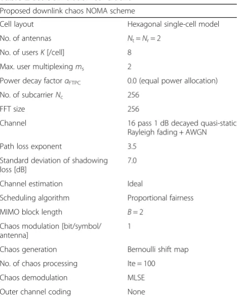
The transmission performance of the C-NOMA scheme by numerical simulations is evaluated and compared to other schemes. The basic simulation conditions are listed in Table2. A downlink transmission is assumed, and a regular hexagonal single cell model whereK= 8 is randomly distrib-uted. The maximum number of multiplexing usersmsis set to 2, and the NOMA transmission with 2-user superimpos-ition or OMA (OFDMA) is appropriately selected. The number of subcarrier in one OFDM frame isNc= 256, and the FFT size is equal toNc. The MIMO block length is set to 2, and one OFDM frame is divided into every consecutive two subcarriers. The total number of subchannels is 128. 2 × 2 MIMO antennas for the BS and each UE, and the channel is 16-path 1 dB-decay quasi-static Rayleigh fading. The path loss exponent and the standard deviation of the shadowing loss are 3.5 and 7.0 dB, respectively. It is assumed that the CSI of all users is fully registered at the BS and UEs, and all keys are shared with the users in the target cell. The user scheduling is conducted by applying the PF criterion on each subchannel, and no outer channel coding was used.
3.1 Transmission performances
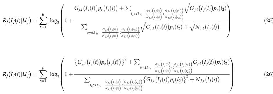
To evaluate the basic transmission performance of C-NOMA, the system average bit error rate (BER) and the average system throughput versus the average re-ceived SNR per antenna at the cell edge are calculated. Additional file4: Figure S4a and b show the BER perform-ance and the system throughput, respectively. In the fig-ures, the reference, BPSK-NOMA transmission which has the same efficiency as C-NOMA, and C-OFDMA with physical layer encryption [14], is plotted along with them. The demodulation schemes for BPSK-NOMA and C-OFDMA are the joint MLD which are nearly identical as in Eq. (24) and MLSE in Eq. (23), respect-ively. In addition, the NOMA power offset αFTPC= 0.4 is applied for BPSK-NOMA in order to prevent degrad-ation by zero signal convergence after superposition, and also to exploit the joint MLD effect. According to this weighted power allocation, the capacity equation for user scheduling is changed to maximize the BER and throughput performances in BPSK-NOMA with joint MLD, and is given as follows:
Table 1Decoding computational complexities
C-NOMA C-OFDMA BPSK-NOMA BPSK-OFDMA
Decoding computational complexities ð2NtBÞms 2NtB 2NtmsB 2NtB
(24)2= 28 24 24× 2 = 25 22× 2 = 23 Table 2Basic simulation conditions
Proposed downlink chaos NOMA scheme
Cell layout Hexagonal single-cell model
No. of antennas Nt=Nr= 2
No. of usersK[/cell] 8 Max. user multiplexingms 2
Power decay factorαFTPC 0.0 (equal power allocation)
No. of subcarrierNc 256
FFT size 256
Channel 16 pass 1 dB decayed quasi-static Rayleigh fading + AWGN
Path loss exponent 3.5
Standard deviation of shadowing loss [dB]
7.0
Channel estimation Ideal
Scheduling algorithm Proportional fairness
MIMO block length B= 2 Chaos modulation [bit/symbol/
antenna]
1
Chaos generation Bernoulli shift map
No. of chaos processing Ite = 100
Chaos demodulation MLSE
where Eqs. (25) and (26) maximize the BER perform-ance and throughput, respectively. These equations are based on the SIC scheme of [13] and are modified using a trial-and-error approach to improve the performances. (Comment 2–4) It is important to verify the performance of the proposed C-NOMA with the theoretical results. Al-though the theoretical analysis of C-MIMO has been stud-ied in [7], the derivation of theoretical C-NOMA-MLSE and BPSK-NOMA-MLD performances in cell model with-out any user distribution limitation is quite complicated. But, in this study, the upper and lower performance limits were demonstrated using a concentric user distribution with inner and outer rings in the simulation.
As a result, it is shown in Additional file4: Figure S4a that the proposed C-NOMA has a large coding gain for the unencrypted BPSK-NOMA transmission. This is be-cause of the channel coding effect generated by the C-MIMO. Compared to the BPSK-NOMA method, its gain is about 5 dB at an average BER of 10−5. (Comment 2–4) When comparing the performance with the upper and lower limits, it was found that the numerical results were within both bounds and the lower limit of C-NOMA is nearly free of any observable error. Note that the upper and lower limits of BPSK-NOMA overlap each other due to the mismatch setting of the power offsetαFTPCfor the concentric user distribution. Also, the BER of a third party without the valid keys (initial values) attempting to de-modulate the transmitted signals, is plotted as“C-NOMA, unsync.” It was observed that the BER becomes 0.5 re-gardless of the average SNR received, and thus the correct information is inaccessible. Therefore, the physical layer security effect is proven with the C-NOMA scheme against a third party without the correct keys. Simi-larly, in Additional file 4: Figure S4b, the performance of the C-NOMA setup is superior to the unencrypted BPSK-NOMA, reaching the maximum throughput when the average SNR is about 15 dB. (Comment 2–4)
This advantage of C-NOMA is also confirmed in compar-ing the upper and lower limits in the figure. Moreover, in comparison with the C-OFDMA method, which is the same encrypted transmission scheme as the proposed C-NOMA technique—although the BER is inferior be-cause the allocated power per user decreases in the case of C-NOMA—the number of accommodated users increases because of the NOMA architecture, and accordingly, the system capacity can be increased while maintaining the physical layer security.
Consequently, based on the above results and details given in Section 2.2.3, the proposed C-NOMA scheme improves the BER performance for unencrypted scheme with the same transmission efficiency. A similar per-formance impact on the throughput was observed for C-OFDMA transmission, which is an encrypted trans-mission scheme, but the compromise is an increase in the calculation complexity during the decoding phase. By exploiting the chaos-based NOMA, both higher cap-acity and physical layer security are achieved.
3.2 Configuration of signal keys and chaos iteration number among users
We investigated the influence of the configuration of sig-nal keys and chaos iteration number among users for the BER performance in the C-NOMA scheme to clarify the restrictions of the signal keys. As presented in Table3, four patterns of key allocation are assumed, and the performances are calculated in each case. Pattern I has the same configurations as in Additional file 4: Figure S4, and for pattern IV, the signal keys and iter-ation number are identical for all users. Pattern II has a different iteration number only, and pattern III has a dif-ferent signal key and iteration number for each user.
As shown in the graph of Additional file 5: Figure S5, a significant degradation appears only in pattern IV and there is no noticeable difference in the BER performance
for the other patterns. The behavior of chaos signal is determined by two elements of the signal key and chaos iteration number, and the same chaos signal is generated only when the same configuration for both parameters is used. In pattern IV, the correlation between the signals to be superimposed becomes high, such that the BER performance is diminished due to the indistinguishable nature of the target and superimposed signals, and also the target signal being irretrievable under equal power allocation. However, from other results, it is clear that the proposed C-NOMA performs adequately only if the signal key or chaos iteration number is different among users. On the other hand, in pattern III, because more varied configurations are used compared to patterns I and II, the security strength in this scenario is enhanced.
3.3 Security evaluation against proximity of initial keys at eavesdroppers
The security capability of the C-NOMA scheme is ana-lyzed in this section. It is assumed that the eavesdropper exists in the cell and tries to replicate the received sig-nals. In this analysis, we use the equivalent channel cap-acityCEas the evaluation index calculated from the BER performance of the eavesdropper [21], which is given as
CE¼NrE½1þPrElog2PrEþð1−PrEÞlog2ð1−PrEÞ;
ð27Þ
whereNrE is the minimum number of transmission and
receiving antennas between the BS and the eavesdropper,
and PrE is the BER of the eavesdropper. The larger the
value of CE, the higher the chances of the eavesdropper
obtaining the transmission data in the system. NrE and
the number of legitimate users is assumed to be 2, while
the maximum value of CE is 2 bit/symbol. It is also
as-sumed that the eavesdropper targets the following sig-nals: [a] OFDMA transmission signal, [b] NOMA transmission signal for a user near the BS, [c] NOMA transmission signal for a user far from the BS. In the
NOMA transmission, ms= 2, and thus, two signal keys
are needed to correctly demodulate the received
super-imposed signal as described inSection 2.2.2. The keys of
the target and superimposed users are designated as the main key and sub key, respectively. Following this stage, the security capability of the different transmission schemes is evaluated. To carry out this analysis, two sce-narios were established as [I] a case where the eaves-dropper obtains the main key via any means and attempts to estimate the sub key, and [II] a case where the eavesdropper obtains the sub key and proceeds to estimate the main key.
Additional file6: Figure S6 shows the equivalent channel capacity of an eavesdropper versus the difference of esti-mated key from the correct key based on the conditions tabulated in Table2. The average SNR at the cell edge per receiving antennas at the eavesdropper is assumed to be either 10 or 20 dB. The horizontal axis in Additional file6: Figure S6 represents the estimation accuracy of the signal key, and the larger this value is, the closer the eavesdrop-per is to obtaining the key of a legitimate user. The results of Additional file6: Figure S6 also reveal that regardless of the scenario, atx= 16, if the accuracy of the estimated key is close to 10−16or more of the correct key, the eavesdrop-per can obtain the entire available information in the sys-tem. Otherwise, the obtained channel capacity is low, and in particular, scenario [II], where the capacity is almost zero regardless of OFDMA or NOMA transmission type. Thus, in the proposed scheme, the integrity of the system can be maintained if the estimation on the main key by the eavesdropper for a target user is insufficient. Accord-ing to the results of scenario [I] in Additional file6: Figure S6a, even in the case that the eavesdropper eventually ob-tains the main key, the desired signal in the C-NOMA transmission system is embedded deeply in the interfer-ence, and the leakage probability is low and below an ac-curacy of 10−16 of the sub key. However, for C-OFDMA signals, the eavesdropper has access to the maximum channel capacity because C-OFDMA signals can be demodulated only with the main key, as described in Sec-tion 2.2.2. In addiSec-tion to capacity enhancement, the pro-posed C-NOMA transmission scheme has an advantage of strong physical layer security because the eavesdropper would require more than two keys for accurate decoding.
4 Conclusions
A downlink chaos non-orthogonal multiple access scheme (C-NOMA), which provided high capacity allocation and physical layer security by applying the principle of C-MIMO scheme was presented in this paper. Simulations results show that the proposed C-NOMA configuration offered not only physical layer security, but also improved BER performance, compared to the conventional power domain NOMA. Furthermore, in comparison with the conventional C-OFDMA method, C-NOMA was demon-strated as a system with enhanced system capacity func-tion. The security capability against an eavesdropper using Table 3Allocation pattern of signal key and chaos processing
number Allocation pattern
Signal keys No. of chaos processing
I c00, 1≠c00, 2≠ ⋯ ≠c00,K Ite1= Ite2=⋯= IteK= Ite
II c00, 1=c00, 2=⋯=c00,K Iteh= Ite + 3(h−1),
(h= 1,⋯,K)
III c00, 1≠c00, 2≠ ⋯ ≠c00,K Iteh= Ite + 3(h−1),
(h= 1,⋯,K)
the equivalent channel capacity was evaluated and showed that a strong security system could be established via mul-tiple user transmission of C-NOMA. Conversely, the pri-mary drawback of this technique is the considerable increase in the decoding complexity for the number of superimposed users.
In future studies, we shall consider a calculation re-duction method for UE decoding in the C-NOMA scheme, and an improvement method for the system performance using an outer channel code concatenation and log-likelihood (LLR) calculation from chaos signals.
5 Methods/experimental
The aim of this study is to propose a new wireless com-munication method. To show the new contributions and their effectiveness, we conducted the numerical simula-tions, in which C programs were constructed and GNU Compiler Collection was used. No experiment involving human participants or animals was conducted.
6 Additional files
Additional file 1:Figure S1.Illustration of a downlink NOMA
transmission scheme. (BMP 4333 kb)
Additional file 2:Figure S2.System model of the base station
transmitter. (BMP 3448 kb)
Additional file 3:Figure S3.System model of a UE receiver. (BMP
2940 kb)
Additional file 4:Figure S4.Comparison of transmission performances
for average SNR received per antenna. (a) Average bit error rate. (b) Average system throughput. (BMP 4074 kb)
Additional file 5:Figure S5.BER performances for different user configurations. (BMP 4299 kb)
Additional file 6:Figure S6.Equivalent channel capacity of the eavesdropper. (a) scenario [I]. (b) Scenario [II]. (BMP 4621 kb)
Abbreviations
LTE:Long-term evolution - Mobile phone standards that were formulated in March 2009 under the third generation partnership project (3GPP) Release 8 at 3GPP, a standards body; ICT: Information and communication technology - Generic name of technology, industry, equipment, service, etc. related to information processing and communication; OFDM: Orthogonal frequency-division multiplexing - One of digital signal modulation methods widely adopted in wireless local area network (LAN) and LTE and so on. By placing each subcarrier orthogonally and densely, this method can effectively utilize the limited frequency band and reduce the influence of multipath in this method; OFDMA: Orthogonal frequency division multiple access - Wireless communication scheme based on OFDM accommodating multiple users. In this scheme, a technique is adopted in which multiple users share subcarriers, and subcarriers with the highest transmission efficiency are allocated to each user; NOMA: Non-orthogonal multiple access - Multiple access method being studied based on the standardization of 5G. By superimposing multiple users non-orthogonally to one subcarrier, large cap-acity communication compared to OFDMA is realized; MIMO: Multiple-input multiple-output - A wireless communication technology which has multiple antennas on the transmitter and the receiver, and transmits data via these devices; C-MIMO: Chaos multiple-input multiple-output - Wireless communi-cation system with physical layer security based on MIMO system which has been proposed in the current study. This scheme is a common-key encryption scheme, and as a result, transmission can be correctly performed only when the same key is shared with the transmitter and receiver, and it also has confi-dentiality to a third party; C-NOMA: Chaos non-orthogonal multiple access - A
multiple access scheme with physical layer security which has been proposed in this paper. In this method, the chaos modulation signal used in chaos MIMO is superimposed in the power domain and transmitted from the transmitter; C-OFDMA: Chaos orthogonal frequency-division multiple access - A multiple ac-cess scheme proposed in this study, in which chaos modulated signals are transmitted based on the OFDMA scheme; BS: Base station - Equipment including antennas and devices for directly communicating with wireless communication terminals; UE: User equipment - A wireless communication terminal such as a cellular phone that communicates with a base station; OMA: Orthogonal multiple access - Unlike NOMA, it is a designation when one user is assigned and communicating on one orthogonal subcarrier;
CSI: Channel state information - State of propagation path between the base station and user terminal; FFT: Fast Fourier transform - Signal processing technique used for the modulation and demodulation processing of OFDM, in addition to frequency analysis of signals such as images/sounds; IFFT: Inverse fast Fourier transform - Similar to FFT, signal processing technique used for the modulation and demodulation processing of OFDM, in addition to frequency analysis of signals such as images/sounds. IFFT is a signal processing operation opposite to FFT; GI: Guard interval - The interval inserted between the symbol to be transmitted and the symbol. Thus, the influence of interference between symbols can be reduced, and it is used in OFDM and OFMDA or the like; SINR: Signal-to-interference noise ratio - A ratio of power other than the desired signal such as power of the desired signal and noise and interference from other cells; MLSE: Maximum likelihood sequence estimation - Signal detection method based on maximum a posteriori probability. The calculation complexity becomes huge in exchange for high detection accuracy; PF: Proportional fairness - One of scheduling methods considering fairness among accommodated users, which is used when allocating subcarriers to users in the multiple access method; FTPC: Fractional transmit power control -A method of power allocation among users in NOM-A transmission; MLD: Maximum likelihood detection - As with MLSE, signal detection method based on maximum a posteriori probability used in the MIMO scheme
Acknowledgements
This work was supported by JSPS KAKENHI, Grant Number JP18K04136.
Funding
JSPS KAKENHI, Grant Number JP18K04136.
Authors’contributions
NH (first author) and EO (second author) made contributions to the project conceptualization and design, and analysis and interpretation of data, and were involved in drafting and revising the manuscript. All authors read and approved the final manuscript.
Authors’information
Naoto Horiike received the B.E. degree in Electrical Engineering from the Nagoya Institute of Technology in 2016. He is currently studying for his in the Master’s degree at the same institution. His research interests include wireless communication and encryption techniques.
Eiji Okamoto received the B.E. degree and the M.S. degree in Electrical Engineering from Kyoto University, Japan in 1993 and 1995, respectively. In 1995, he joined the Communications Research Laboratory (CRL), Japan. He also received the Ph.D. degree from the same university. Currently, he is an Associate Professor at Nagoya Institute of Technology. His current interests include coded-modulation, satellite communication, and mobile communication systems. He is a member of IEICE and IEEE.
Tetsuya Yamamoto received the B.E. degree in Electrical, Information and Physics Engineering in 2008 and M.S. and Dr. Eng. degrees in communications engineering from Tohoku University, Sendai, Japan, in 2010 and 2012, respectively. From April 2010 to March 2013, he was a Japan Society for the Promotion of Science (JSPS) research fellow. Since April 2013, he has been with Panasonic Corporation. He was a recipient of the 2008 IEICE RCS (Radio Communication Systems) Active Research Award and the Ericsson Best Student Award in 2012.
Competing interests
The authors declare that they have no competing interests.
Publisher’s Note
Author details
1Graduate School of Engineering, Nagoya Institute of Technology, Nagoya,
Aichi, Japan.2Core Element Technology Development Center, Panasonic
Corporation, Yokohama, Kanagawa, Japan.
Received: 27 November 2017 Accepted: 30 May 2018
References
1. 3rd Generation Partnership Project (3GPP), RWS-120010, NTT DOCOMO, Requirements, Candidate Solutions & Technology Roadmap for LTE Rel-12 Onward, 2012.
2. 3rd Generation Partnership Project (3GPP) TR38.912 (14.1.0), Study on new radio access technology (release 14), 2017.
3. 3rd Generation Partnership Project (3GPP) TR38.913 (14.3.0), Study on scenarios and requirements for next generation access technologies (release 14), 2017.
4. 3rd Generation Partnership Project (3GPP) TS 36.211 (V10.7.0), Evolved Universal Terrestrial Radio Access (E-UTRA); Physical Channels and Modulation, 2013.
5. (comment #2-1) K. Higuchi and A. Benjebbour, Non-orthogonal multiple access (NOMA) with successive interference cancellation for future radio access. IEICE Trans. CommunE98-B(3), 403–414 (2015)
6. Y Saito, Y Kishiyama, A Benjebbour, T Nakamura, L Anxin, K Higuchi, Non-orthogonal multiple access (NOMA) for cellular future radio access Proc. IEEEVTC2013Spring, 1–5 (2013)
7. E Okamoto, A chaos MIMO transmission scheme for channel coding and physical-layer security. IEICE Trans. Commun.E95-B(4), 1384–1392 (2012) 8. N Horiike, H Kitagawa, E Okamoto, and T. Yamamoto, Chaos MIMO-based
downlink non-orthogonal multiple access scheme with physical layer security Proc. the 15th IEEE Annual Consumer Communications & Networking Conference (CCNC 2018), 1–7, 2018.
9. Y Li, M Jiang, Q Zhang, Q Li, J Qin, Secure beamforming in downlink MISO nonorthogonal multiple access systems. IEEE Trans. Veh. Technol.66(8), 7563–7567 (2017) (Comments #1-1, #1-4, #2-2, #3-6)
10. M Jiang, Y Li, Q Zhang, Q Li, J Qin, Secure beamforming in downlink MIMO nonorthogonal multiple access networks. IEEE Signal Process. Lett.24(12), 1852–1856 (2017)
11. Y Zhang, H-M Wang, Q Yang, et al., Secrecy sum rate maximization in non-orthogonal multiple access. IEEE Commun. Lett.20(5), 930–933 (2016) 12. M Tian, Q Zhang, S Zhao, Q Li, J Qin, Secrecy sum rate optimization for
downlink MIMO nonorthogonal multiple access systems. IEEE Signal Processing Letters24(8), 1113–1117 (2017)
13. Y Liu, Z Qin, M Elkashlan, Y Gao, L Hanzo, Enhancing the physical layer security of non-orthogonal multiple access in large-scale networks. IEEE Transactions on Wireless Communications16(3), 1656–1672 (2017) 14. Z Ding, Z Zhao, M Peng, HV Poor, On the spectral efficiency and security
enhancements of NOMA assisted multicast-unicast streaming. IEEE Transactions on Communications65(7), 3151–3163 (2017)
15. E Okamoto, Y Inaba, A Tanaka, Chaos-MIMO-OFDMA scheme achieving secure multiple access at physical-layer. Proc. IEEE, APWCS2013 , 26-30 (2013) 16. G Alvarez, S Li, Breaking an encryption scheme based on chaotic baker
map. Phys. Lett. A352, 78–82 (2006)
17. G Alvarez, JM Amigo, D Arroyo, S Li,Lessons learnt from the cryptanalysis of chaos-based ciphers, in L. Kocarev, S. Lian (Eds.), Chaos based cryptography theory algorithms and applications, Springer-Verlag(2011), pp. 257–295 18. GRP Box, ME Muller, A note on the generation of random normal deviates.
Annals Math. Stat29, 610–611 (1958)
19. E Okamoto, N Horiike, Performance improvement of chaos MIMO scheme using advanced stochastic characteristics. IEICE Communications Express
5(10), 371–377 (2016)
20. A Benjebbour, L Anxin, Y Saito, Y Kishiyama, A Harada, T Nakamura, System-level performance of downlink NOMA for future LTE enhancements. Proc. IEEE Globecom, pp., 66–70 (2013)