Volume 2009, Article ID 894726,11pages doi:10.1155/2009/894726
Research Article
Downlink Assisted Uplink Zero Forcing for TDD Multiuser
MIMO Systems
Petri Komulainen, Antti T¨olli, Matti Latva-aho, and Markku Juntti
Centre for Wireless Communications, University of Oulu, P.O. Box 4500, 90014 Oulu, Finland
Correspondence should be addressed to Petri Komulainen,[email protected]
Received 1 February 2009; Revised 11 May 2009; Accepted 19 July 2009
Recommended by Bruno Clerckx
This paper proposes practical coordinated linear transmit-receive processing schemes for the uplink (UL) of multiuser multiple-input multiple-output (MIMO) systems in the time division duplex (TDD) mode. The base station (BS) computes the transmission parameters in a centralized manner and employs downlink (DL) pilot signals to convey the information of the beam selection and beamformers to be used by the terminals. When coexisting with the DL transmit-receive zero forcing, the precoded DL demodulation pilots can be reused for UL beam allocation so that no additional pilot overhead is required. Furthermore, the locally available channel state information (CSI) of the effective MIMO channel is sufficient for the terminals to perform transmit power and rate allocation independently. In order to reduce the UL pilot overhead as well, we propose reusing the precoded UL demodulation pilots in turn for partial CSI sounding. The achievable sum rate of the system is evaluated in time-varying fading channels and with channel estimation. According to the results, the proposed UL transmission strategy provides increased rates compared to single-user MIMO transmission combined with user selection as well as to UL antenna selection transmission, without being sensitive to CSI uncertainty.
Copyright © 2009 Petri Komulainen et al. This is an open access article distributed under the Creative Commons Attribution License, which permits unrestricted use, distribution, and reproduction in any medium, provided the original work is properly cited.
1. Introduction
In order to attain all the capacity gains available in multiple-input multiple-output (MIMO) communication systems, channel state information in the transmitter (CSIT) should be utilized. CSIT is available in time division duplex (TDD) systems, provided that the channel does not change significantly between the receive and transmit periods. Due to the channel reciprocity, the receiving node can estimate the state of the channel during one frame, and use that knowledge for the purposes of MIMO transmission in the next one. CSI can be estimated from pilot symbols that are known to the receiver. The pilots are also necessary for performing coherent demodulation in the receiver side. In order to keep the pilot overhead as low as possible, it is desirable that the same pilot symbols are a useful reference for both reception and transmission.
In a cellular multiuser MIMO system, the downlink (DL) comprises a broadcast channel (BC), whereas the uplink (UL) is a multiple access channel (MAC). The channel
reci-procity leads into duality properties between the BC and MAC [1,2]. When designing the user multiplexing strategy for a MIMO system, both directions need to be taken into account together. A distinctive difference between the base station (BS) and the user terminals is that the BS can have the CSI of the channels to all the terminals, while the terminals only have access to the CSI of their individual radio channels. Thus, the BS is capable to centralized processing to attain space division multiple access (SDMA). On the other hand, the terminals can attempt SDMA like transmission only based on the information contained in the signal received in the DL.
paper is to study the DL transmission, and to propose a prac-tical matching UL beamforming method for improving the capacity of the cellular system. The underlying assumption is that both the DL and the UL employ orthogonal frequency division multiplexing (OFDM), where the frequency-time resource blocks experience essentially flat fading.
Zero forcing DL transmission by a multiantenna BS provides SDMA in which intracell multiuser interference is nulled. For single-antenna terminals, zero forcing (ZF) is achieved simply by channel inversion in the transmitter [4]. Coordinated transmit-receive processing with block diagonalization (BD) is a zero forcing SDMA scheme that supports also multiantenna user terminals [5]. It decouples the MIMO channels of different users so that precoding based on singular value decomposition (SVD) can be carried out individually for each user. Our preferred transmit-receive solution is obtained when the terminals employ conventional maximal ratio receivers (MRCs) as suggested in [6]. In that case, the ZF solution can be found via an iterative algorithm that was proposed in [7], and further studied in [8]. While corresponding general closed form solutions have not been presented, in [9] it was derived for a two-user case and in [10] the solutions for a three-user setup were studied.
It is beneficial to combine multiuser beamforming with greedy beam selection [11]. In the context of multiuser MIMO DL with coordinated transmit-receive processing, greedy beam selection was studied in [12,13].
In a time-varying fading radio channel the CSI obtained during the TDD receive frame is already partially outdated when the transmit frame starts. Therefore, the CSI contains a lag error that has a decremental impact on the system performance. The effect of delayed CSI in case of single-user MIMO communications was studied in [14], and in case of DL multiuser MIMO systems in [15]. In addition to the lag error, the effect of noisy CSI estimation on multiuser multiple antenna systems was analyzed in [16].
Based on the principles of DL multiuser transmit-receive zero forcing and beam selection, in this paper, we propose a corresponding communication strategy for the UL. In [17], we presented a similar approach based DL BD by transmit processing only. While in that simple form of BD, the number of antennas in the BS must always be equal to or larger than the aggregate number of antennas in the user terminals [5], the strategy described here can support more general antenna setups and resource allocation methods. We also evaluate by simulations the impact of imperfect CSI estimation as well as lag error on the achievable rates in the system.
While the algorithms for multiuser processing and beam selection are known from literature, the main contribution of our work consists of two novel signaling concepts. The first concept is to convey the UL beamforming parameters to the terminals by means of DL pilot signals. The second concept is to append the UL demodulation pilot signal with additional pilot beams so that the combined signal serves as a full CSI sounding pilot. While the both new techniques can be applied in TDD systems separately, we introduce them as features supporting a combined uplink-downlink strategy with reduced pilot overhead. As a result, the precoded pilot
symbols are sufficient in both UL and DL to satisfy the needs of both transmission and reception.
The paper is organized as follows. In Section 2, the generic uplink-downlink multiuser MIMO system model is described. Section 3 summarizes the ideas of coordinated transmit-receive processing and beam selection. Section 4
presents the details of the proposed uplink-downlink beam-forming scheme, and inSection 5, numerical capacity analy-sis results are given. Finally,Section 6concludes the paper.
2. System Model
We consider a MIMO system with one base station having
NBantenna elements, andKuser terminals withNUantenna
elements each. Furthermore, we assume the users are symbol synchronous, and that each userk∈ {1, 2,. . .,K}is allocated withLk ≤ Ndata streams in both UL and DL, whereN =
min(NB,NU). We denote the set of active, that is, scheduled
users asK= {k|Lk>0}.
The complex DL MIMO signal received by the terminal of userkat symbol intervalncan be written as
xdk(n)=Hk
i∈K
MdiAdibdi(n) +zdk(n), (1)
where Hk ∈ CNU×NB is the channel matrix, Mdk =
[mdk,1· · ·mdk,Lk] ∈ CNB×Lk is the DL transmit precoder
matrix with unit norm column vectors,Adk=diag(
pd
k,1,. . .,
pd
k,Lk) is the real-valued diagonal transmit amplitude
matrix,bdk(n)∈CLk×1is the data symbol vector, andzd k(n)∈ CNU×1is a white Gaussian noise vector with varianceN
0per
element. Similarly, the UL signal received by the BS becomes
xu(n)=
i∈K
HTiMuiAuibui(n) +zu(n), (2)
whereMu
k = [muk,1· · ·muk,Lk]∈ C
NU×Lk is the UL transmit
precoder matrix with unit norm column vectors, andAu k =
diag(puk,1,. . .,
puk,Lk) is the diagonal transmit amplitude
matrix. Here, ()Tdenotes matrix transpose, and for complex conjugation and conjugate transposition, notations ()∗ and ()H are used, respectively. The signal model is free from intersymbol interference; this can be realized, for example, by OFDM.
For the purposes of spatial processing, we write the singular value decomposition of the individual MIMO channel of userkas
Hk=UkΛkVHk, (3)
where the matrices Uk = [uk,1· · ·uk,N] ∈ CNU×N,Vk =
[vk,1· · ·vk,N] ∈ CNB×N, and Λk = diag(λk,1,. . .,λk,N)
We also define generic linear receivers Wdk =
[wdk,1· · ·wdk,Lk] ∈ CNU×Lk and Wu
k = [wku,1· · ·wuk,Lk] ∈
CNB×Lk. Depending on the transmit precoders and receivers,
signal-to-interference-plus-noise ratio (SINR) can be calculated for each stream [8]. Assuming the data streams are uncorrelated, SINR for streamsof userkin UL direction is
in DL. Furthermore, by assuming Gaussian symbol alpha-bets, the mutual information between the transmitted sequence and decision statistics per stream becomes
Rk,s=log2
1 +γk,s
bits/s/Hz, (6)
which is also an upper bound for the achievable data rate.
3. Coordinated Transmit-Receive Processing
Coordinated transmit-receive processing by block diagonal-ization is a known method for DL zero forcing [5]. It can support any number of antennas in the BS and the terminals as well as flexible beam allocation. The DL signal processing chain is depicted in Figure 1(a). Let Fk ∈ CNU×Lk be an
orthonormal receiver processor matrix for userk. The zero forcing criterion between users can be expressed as
FHkHkCi=0, i /=k, (7)
which implies that the receiver finishes up the zero forcing by rejecting the residual interference seen in the receiver antennas. To enable this, the interference must lie in the (NU−Lk)-dimensional subspace orthogonal to the columns
ofFk. The task of the transmit processorCkis to ensure this
property.
The effective single-user MIMO DL channels are further decomposed intoLkparallel channels as
Hk=FHkHkCk=UkΛkV H
k, (8)
where Λk = diag(λk,1,. . .,λk,Lk), in order to apply SVD
precoding so that the DL precoding matrix for user k is
Mdk=CkVkand the corresponding receiverWdk=FkUk.
The multiuser MIMO system is effectively decoupled into a set of single-user MIMO links. Thus, power and rate allocation can be decoupled from the precoder design, and conventional coding and modulation methods can be applied. The achievable system sum rate becomes
Rsum=
Receiver Channel TX precoder TX power
Ck Ak
u u
u
Vk Uk
(b)
Figure1: Ideal signal processing chain for multiuser zero forcing: (a) downlink, (b) uplink.
wherepk,sis the transmit power allocated to the eigenmodes
of userk.
In the coordinated transmit-receive processing, the BS computes all the transmitters and corresponding receivers in a centralized manner, based on the CSI of the selected users. In this section, the processing is described with the assumption that the channel matrices Hk are known. In Section 4 we explain how the UL pilot responses of our proposed strategy can be applied as a reference instead.
3.1. Closed-Form ZF Solution. The solution for (7) is not unique, as the receive processorsFkcan be selected in
multi-ple ways. One simmulti-ple choice is to choose the column vectors associated to the strongest singular values from matrix Uk
in (3) as suggested in [5]. Let U(1)k = [uk,1· · ·uk,Lk] ∈
CNU×Lkcontain theL
kselected left singular vectors andV(1)k =
[vk,1· · ·vk,Lk] ∈ C
NB×Lk the corresponding right singular
vectors. The zero forcing criterion becomesU(1)Hk HkCi =0,
which can be shown to be equivalent toV(1)Hk Ci=0.
The decomposition (8) lends itself for the purposes of UL transmission as well, as the effective UL MIMO channel is a transposed version of the DL so thatHTk = CTkHTkF∗k =
V∗kΛkU T
k. Thus our proposed UL signal processing chain is
ideally a reversed version of the DL so that the receivers become transmitters and vice versa, as shown inFigure 1(b). Consequently, the zero forcing criterion in the UL is equivalent to (7), that is,CTiHTkF∗k =0, i /=k. Since in both
directions the eigenmodes of the effective MIMO channels are the same, and as the interference is nulled both ways, for each user the UL and DL are essentially equal. The achievable rates differ only if different transmit powers are applied or if the background noise levels seen by the BS and the terminal are different.
ideally, the terminal side needs not actively estimate and suppress interference.
In the iterative algorithm the processorsFkare initialized
by matrix U(1)k , and then the transmitter Ck and receiver
Fk processors for each user are optimized successively until
orthogonality between the users is achieved [7, 8]. After convergence, the received DL stream responses dedicated to userkareHkCkVk=FkΛk, which implies that the final zero
forcing receiver matrix is a set of matched filters.
In our simulations, in the case ofNB =4,NU =2, and K = 4, the iterative algorithm converged on the average in less than five iterations. Our stopping condition of the algorithm required that the sum of the absolute values of all cross termsFH
kHkMdi must be less than 10−4.
3.3. Greedy Beam Selection. Greedy beam selection is a process of allocating beams to the users based on their individual channel conditions and spatial compatibility [11]. In the context of the multiuser MIMO system and zero forcing, beam selection has been studied in [12, 13]. The algorithm consecutively selects at mostNS=min(KNU,NB)
eigenbeams from the total set of K · min(NU,NB) to be
allocated. Number NS indicates the number of degrees of
freedom available in the system.
First, the strongest eigenbeam, that is, the one with the largest singular value λk,s among all users is selected.
Subsequently, on each step of the selection process, the beam having the largest component orthogonal to the previously selected beams is chosen as
(k,s)=arg max
k,s
I−SSHS−1SH
λk,svk,s
, (10)
where matrix S contains as columns all the right singular vectorsvk,scorresponding to the previously selected
eigen-beams. Note that theLk eigenbeams selected for userkare
not necessarily the strongest, since weaker beams may be preferred due to their better spatial compatibility properties. The selection process stops if the calculated capacity of the system is reduced compared to the previously selected beam set. Thus, there may be fewer active streams in the system than there are degrees of freedom. In this paper, the stopping condition is always calculated based on the closed-form zero forcing solution in order to avoid multiple zero forcing iteration rounds.
The role of the beam selection is to make the problem of zero forcing relatively easy, by ensuring that the selected eigenbeams are nearly orthogonal so that the zero forcing loss remains acceptable. The stopping condition of the selection has a similar effect, as the algorithm rather stops than chooses more linearly dependent eigenbeams.
A straightforward simplification to the multiple access protocol can be introduced by restricting the maximum number of beams per user to be one, that is, Lk ≤ 1.
Especially when the number of users is high, the effect of the restriction on the system throughput is minor. However, by allowing multiple data streams per user, higher user peak data rates can be provided.
Base station
U1
U2
U3
Figure2: Example of uplink-downlink beam selection.
In our proposed strategy, the same beam set is selected both for UL and DL. An example outcome of the selection is depicted inFigure 2.
4. Uplink-Downlink Beamforming Strategy
The main contribution of this paper consists of two novel concepts. The first concept is to convey the uplink (UL) beamforming parameters to the terminals by means of downlink (DL) pilot signals. The second one is to append the UL demodulation pilot signal with additional pilot beams so that the combined signal serves as a CSI sounding pilot. While the both new techniques can be applied in TDD systems separately, we introduce them as features supporting a combined uplink-downlink strategy with reduced pilot overhead.
Most of the intelligence as well as the computational complexity of the proposed strategy lie in the base station (BS) that carries out the multiuser processing, including beam selection and precoding. On the other hand, the terminals essentially perform single-user MIMO processing in conjunction with interference suppression.
4.1. Signaling for Uplink Beamforming. The resource alloca-tion and pilot signaling in TDD mode are in general open research problems and standardization issues. Due to the TDD channel reciprocity, the need for CSI quantization can be avoided unlike in the FDD mode. Thus, in principle, TDD can support more advanced spatial signal processing meth-ods than FDD. However, reasonable pilot signal overhead is still required, and due to estimation errors CSI is not perfect. In order to facilitate fast advanced centralized processing in the BS, antenna-specific UL CSI sounding pilots are needed [3]. These pilots enable any form of multiuser MIMO precoding in the DL.
Time
Figure3: Simplified TDD frame and pilot structure needed for (a) UL beamforming, (b) UL/DL beamforming.
zero forcing multiplexing, and assuming knowledge of the background noise level at the receiving end, each terminal may then locally decide on the power control, modulation and coding of its UL data streams, without the need for the BS to communicate this to the terminal. In order to facilitate reception at the BS, the UL data includes embedded demodulation pilot symbols. The signaling sequence is depicted inFigure 3(a).
A more conventional signaling choice for the BS is to distribute quantized information, indicating desired UL precoders chosen from a predefined codebook. Due to the limited size of the codebook, perfect orthogonality between the users’ effective channels cannot be ensured. Thus, in order to guarantee the UL decoding result, user-specific transmit power and rate parameters should be communicated as well. Comparison of the two schemes is presented in Table 1. In the simplest case, the quantized signaling can support UL antenna selection transmission, where the BS chooses a subset of terminal antennas that each simultaneously transmits one independent unprecoded data stream. This method is used as a benchmark in the simulations.
One more obvious method to facilitate UL precoding is to employ a DL common pilot so that each terminal can form beams based on the knowledge of its individual MIMO channel. However, this mode does not easily allow centralized multiuser control, and the resulting UL beams may end up undecodable if they are not spatially compatible.
4.2. Combined Uplink-Downlink Signaling. When applying multiuser MIMO precoding in the DL, the DL demodulation pilots may be reused as beam allocation pilots as shown in Figure 3(b). In this approach, the same spatial beams are active in both directions, and the need for specific DL
Table1: UL MU beamforming approaches.
Method UL signaling DL signaling Power and rate control
signaling of the desired UL precoders is removed. On the other hand, the UL demodulation pilots can be reused for partial CSI sounding. By adding parallel pilot beams, full CSI sounding can be achieved, as described in the following subsection. As a result, the amount of required specific CSI sounding pilot overhead is reduced.
For example, in our simulation setup withK =4,NB =
4, andNU = 2, coupling of the UL and DL beamforming
halves the required DL pilot overhead. At the same time, the UL pilot overhead is reduced approximately by one third.
Obviously, the combined strategy sets constraints to the overall resource allocation of the system, as the same frequency resource blocks are assumed to be allocated to the same users in both UL and DL. Therefore, the concept is at its most efficient when the offered data traffic loads in both directions are approximately equal. In the system level, the possible asymmetry of the traffic can be treated in time domain, for example, by allocating more time frames to the DL than UL. Furthermore, the concept of reusing the demodulation pilot signals for CSI sounding and beam allocation can be utilized whenever the receive frame is close enough to the corresponding transmit frame. In other times, separate sounding pilots need to be employed.
4.3. Pilot Responses. Pilot symbols transmitted with beam-forming via the same precoders as data are necessary in order to facilitate coherent demodulation. However, unlike data, we propose that the pilots have equal power allocation per stream. This way the channel gains can be correctly observed from the received signal without getting mixed with the amplitude adjustment caused by power allocation, and the pilot responses can be utilized for the purpose of transmit precoding as well.
For CSI sounding, it is necessary that the UL pilots of each user fully span the NU-dimensional transmit signal
space even when the number of data streams Lk is lower
thanNU. Therefore, we propose appending theLk UL pilot
streams associated with the allocated data streams by another
NU−Lkpilot streams. Thus, the unitary pilot precoder matrix
becomes
Due to pilot precoding, neither the BS nor the terminals have explicit knowledge of channel matricesHkbut only the
pilot responses. Excluding the transmit power and noise, the pilot responses are
for DL and UL, respectively. In the DL, Rd
k,i denotes the
response seen by userkof the signal transmitted to useri. The number of required pilot streams in UL isK·NUand
increases with the number of simultaneous users, whereas for DLNB pilot streams always suffice. Thus, the UL limits the
practical number of users to be included in the same spatial processing group.
4.4. Base Station Processing. Section 3 described how the coordinated transmit-receive processing and beam selection are carried out by the BS, based on the knowledge of the MIMO channelsHk. However, the same computations can
be realized by replacing the channel matrices with the UL pilot responses RuTk = MuTk Hk ∈ CNU×NB as well, since the
right singular vectors (3), forming the transmit signal space, and the corresponding singular values are invariant to the multiplication by the unitary pilot precoder matrix. As a result, the BS obtains the same set of transmit precoders and powers as when applying the channel matrices directly. On the other hand, the set of receiver processors the algorithm assumes will be different.
LetFk ∈CNU×Lkbe the orthonormal receiver processor
matrices andCkthe orthonormal transmit processor
matri-ces, k ∈ K, given by the zero forcing algorithm—closed-form or iterative—at the BS after applying the UL pilot responses as a reference. These processors satisfy, instead of (7), the condition
the user terminal k applies in order to reject multiuser interference. This processor must satisfyFHkHkCi=0, i /=k.
By comparing to (13) we can see thatFk=M
u∗
k Fkis the valid
orthonormal zero forcing processor at the terminal.
The underlying assumption in the transmit-receive zero forcing strategy is that the receivers employed both in the DL and the UL are zero forcing detectors. However, the actual receiver side may construct other more advanced or robust detectors in order to improve performance. In addition to zero forcing (ZF), linear minimum mean square error (LMMSE) detectors are considered here. Both receiver types can be formulated for arbitrary transmit precoders and channel responses. Let us stack the UL stream responses and transmit amplitudes into large matricesRu=[Ru
1· · ·RuK]∈ CNB×LandAu = diag(Au
1,. . .,AuK), respectively, whereL =
kLkis the total number of streams to be detected. The ZF
and LMMSE UL multiuser receivers become
WuZF=RuRuHRu−1, (14)
respectively. Here, the user-specific receivers are stacked in the large result matrix as Wu = [Wu
1· · ·WuK] ∈ CNB×L.
Note that for our proposed UL precoding, the ZF receiver is ideally equivalent to the corresponding DL precoderCkVk.
In practice, however, due to estimation errors, channel time-variations and other nonidealities, the receiver must always rely on the received stream responses.
4.5. Terminal Processing. In the DL, the total number of allocated streams is usually larger than the number of receiver antennas in one terminal, that is,NU< L. Therefore,
the terminal may not be able to perfectly cancel interference if the DL precoding was not perfect, and in this case the strict ZF receiver may be replaced with the least norm (LN) receiver. Let us again stack the stream responses into a large matrixRkd=[Rdk,1· · ·Rdk,K]∈CNU×Lso that the user-specific
ZF/LN receiver can be expressed as
Wdk,ZF/LN=Rdk,kRdkHRdk−1, NU> L,
Wdk,ZF/LN=RdkRdkH−1Rdk,k, NU≤L.
(16)
Note that in the case of the proposed DL precoding, ideally the ZF/LN receiver results in a true ZF receiver, even when
NU< L. Furthermore, we formulate the LMMSE receiver as
Wd
transmit-receive processing, in an ideal case, both the ZF/LN and the LMMSE receiver are equivalent to the matched filter (MF)Wk,MF=Rdk,k.
The transmit precoding for the UL relies on the locally available CSI of the effective MIMO channel and the reversal of the DL signal processing chain. The receive beamformers can be used in turn as transmit precoders. Let Rd
k,k =
[rd
k,1· · ·rdk,Lk] be the received DL response matrix of user
k, and [wd
k,1· · ·wdk,Lk] the corresponding ZF/LN receiver
However, if the DL precoding was not ideal, or the terminal receiver is formulated based on estimated channel, the receive beamformers of userkdo not necessarily remain orthogonal to each other. A conceptually straightforward way to orthonormalize the receive beamformers, and to simultaneously obtain the additional NU − Lk UL pilot
precoders, is to perform full SVD as Wd
k = U˙kΛk˙ V˙Hk, and
to set Muk = U˙∗k ∈ CNU×NU, where the first Lk columns
correspond to the data streams. This method was used in the simulations of this paper.
It is worth noting that even when the terminal employs the LMMSE receiver, in the closed-form transmission mode, the transmit precoders are still calculated based on the ZF/LN receivers. In the iterative zero forcing mode, when operating with estimated CSI, it turned out that the MF receiver is the best reference for UL precoding, even though as a receiver ZF/LN performs better.
4.6. CSI Uncertainty. The treatment in the previous sections considered error-free CSI. In practice the beam selection, transmit precoding, and receiving have to be carried out based on noisy channel responses experienced during the latest received frame prior to transmission. In a time-varying channel this results in a lag error in transmit CSI. As a result, the orthogonality between users and streams in DL is partially lost. Also in the UL, the channel reciprocity is reduced. In the receiver side, the pilot reference is timely and correct so that both the desired signal and interference responses can be estimated and utilized without lag error.
We assume that the pilot symbol sequences associated with different streams and users are all mutually orthogonal, which accommodates interference free channel or pilot response estimation. For zero forcing transmit and receive processing, the estimation of the pilot responsesRukandRd
k,iis
adequate. On the other hand, in order to construct LMMSE receivers, the spatial signal covariance or the transmit amplitudesAu
k andAdk need to be known or estimated. For
our simulations, the estimation of signal covariance is carried out as described in [17].
In the following, we exclude the user indexes and discuss how different error sources accumulate to the performance of the proposed system. The performance depends on the transmit precoders and receiver filters as indicated by (4) and (5). The choice of the unitary UL pilot precoder matrix
Muhas no effect on the DL precoding, whereas the DL pilot precoders affect the UL data precoding. The precoders are formed based on estimated pilot responses, so that
Md(n)=f
B
Ru(n−1)
,
Mu(n)=fU
Rd(n−1),
(19)
where n is the frame index, and fB and fU denote the
precoding algorithms running in the BS and in the terminals, respectively. LetDbe the channel lag error so thatH(n−1)=
H(n) +D(n). By denoting estimation noiseE, the estimates in BS become
Ru(n−1)=(H(n) +D(n))TMu+Eu(n−1) (20)
and in the terminal side
Rd(n−1)=(H(n)+D(n))Md(n−1)+Ed(n−1), (21)
which indicates that the error sources seen in both UL and DL accumulate to affect the UL transmission.
5. Numerical Results
Different multiuser MIMO scenarios were simulated in frequency flat fading with Jakes’ Doppler spectrum and uncorrelated channels between antennas. We denote the Doppler spread DS = 2fd where fd is the maximum
Doppler shift. The equal length UL and DL TDD frames of durationTframefollow each other consecutively as illustrated
inFigure 3(b). Each simulation comprises 20 000 randomly generated, independent channel process bursts of several frames. The channel coefficients remain constant over each frame. System signal-to-noise-ratio SNR was set to 10 dB, and it is defined as kPk/N0. All the methods compared
employ the same sum transmit power.
In order to compare the effect of spatial processing between DL and UL, we apply here the same power constraints in both directions. This is a reasonable assump-tion in office deployments or femto-cells, where the base station does not employ significantly higher transmit powers compared to the mobile devices. As a result, the supported rates in the UL and DL are ideally equal. In our simple and primitively fair allocation rule, each user is granted with a share of the total transmit power, proportional to the number of beams it was allocated. That is,
Pk=P·Lk iLi
, (22)
wherePis the total transmitted power in the cell.
One of the simulated benchmark methods is the UL antenna selection transmission, where the BS chooses a subset of terminal antennas that simultaneously transmit one independent unprecoded data stream each. Here, the greedy selection algorithm (10) is applied so that the channel singular vectors are replaced by channel vectors, that is, by rows from matricesHk. Thus, centralized multiuser control
is exercised in order to ensure the spatial compatibility of the concurrent transmissions. Equal transmit power per antenna is allocated, and multiple data streams per user are allowed. While antenna selection is simpler compared to the UL beamforming, it offers no reduction to the required pilot overhead, since the UL CSI sounding pilots are still needed for reference.
Another comparison scheme is the single-user MIMO transmission, “best-user SVD”, where the user with the strongest MIMO channel is always chosen for single-user MIMO transmission by SVD precoding. In that frame, the transmit power of the cell is allocated to one user.
Figure 4shows the sum rate performance of the different schemes versus the number of usersK, in conjunction with greedy beam selection and perfect CSI in static channel (DS = 0) for NB = 4 BS antennas and NU = 2
1 2 3 4 5 6 7 8 5
6 7 8 9 10 11 12 13 14 15 16
Number of users
Su
m r
at
e (bits/Hz/s)
ZF closed form (greedy)
ZF closed form (greedy), max 1 beam per user ZF iterative (greedy)
ZF iterative (greedy), max 1 beam per user Nonlinear TX-RX (greedy)
Sum rate capacity Best user SVD
UL antenna selection (greedy)
Multi-user MIMO, NB= 4, NU= 2, SNR = 10 dB
Figure4: Average sum rate versus number of users, with ideal CSI, NB=4,NU=2,DS=0.
always outperforms the closed-form solution. Furthermore, as the number of users grows, the loss from restricting the maximum number of beams per user to be one is reduced. Here the comparison curve “nonlinear TX-RX” refers to the capacity figures obtained by iterative waterfilling for the greedy beam allocation and with the power constraint (22). The difference to the ZF curves represents the capacity loss induced when restricting transmit-receive processing to be linear. The sum rate capacity shown in the figure is the sum rate achievable with the sum power constraint [18]. As can be seen, the single-user MIMO transmission is inefficient in the sense that it cannot utilize more thanNUout of the NB potential spatial degrees of freedom available. On the
other hand, the UL antenna selection shows competitive performance, and it benefits from multiuser diversity as much as the beamforming methods. The only difference is caused by the absence of beamforming gain.
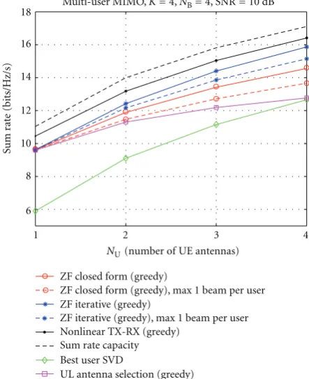
The effect of the number of terminal antennasNUwhen K = 4, is illustrated in Figure 5. With a higher number of antennas, all the beamforming methods benefit from the increased beamforming gain, while the advantage seen by the antenna selection is more limited. For the compared methods, CDFs of the sum rates for the special caseK =4 andNU=2 are depicted inFigure 6.
Figure 7illustrates the effect of temporal fading and lag error of transmit CSI on the UL and DL schemes in a network of four users and with ZF receivers. As can be seen, DL is more sensitive to the lag error than the UL. The antenna selection is affected as well, as the selection is based on
1 2 3 4
6 8 10 12 14 16 18
NU (number of UE antennas)
Sum r
at
e (bits/Hz/s)
ZF closed form (greedy)
ZF closed form (greedy), max 1 beam per user ZF iterative (greedy)
ZF iterative (greedy), max 1 beam per user Nonlinear TX-RX (greedy)
Sum rate capacity Best user SVD
UL antenna selection (greedy)
Multi-user MIMO, K= 4, NB= 4, SNR = 10 dB
Figure5: Average sum rate versus number of terminal antennas, with ideal CSI,NB=4,NU=2,DS=0.
outdated observations, and the spatial compatibility of the antennas is reduced.
Figure 8depicts the effect of noisy channel estimation in static channel forNB=4,NU=2, andK=4. The achievable
rates are shown versus pilot sum SNR=NpilotPpilot/N0, where
Npilotis the number of pilot symbols per frame, and Ppilot
is the total pilot power in both UL and DL. In the DL, the power is equally divided between the kLk pilot streams,
while in the UL the power is divided betweenK·NUpilot
streams. The rates are averages over data fields only so that the fractional rate loss caused by the pilot overhead is not included. In Figure 8(a)the CSIR is assumed ideal so that all receivers operate on perfect channel knowledge, whereas the CSIT is noisy so that the transmit beamformers become imperfect. In the UL, the CSIT uncertainty accumulates from the estimation of both CSI sounding and the following beam allocation. For the antenna selection, the only source of error is the CSI sounding step. As can be seen, the iterative ZF method in UL outperforms the comparison schemes with any pilot SNR value. Figure 8(b) shows the accumulated effect of CSIT and CSIR uncertainty. As can be seen, the UL reception suffers more than DL from the reduced receiver performance, and the multiuser strategies suffer more than the single-user case. In the simulation setup, this is partially caused by the fact that UL pilot power has been distributed between the demodulation and additional CSI sounding pilots, which is inefficient from the receiver point of view.
6 7 8 9 10 11 12 13 14 15 16 17 0
Sum rate (bits/Hz/s)
P
r (sum r
at
e
<
abscissa)
ZF closed form (greedy)
ZF closed form (greedy), max 1 beam/user ZF iterative (greedy)
ZF iterative (greedy), max 1 beam/user Nonlinear TX-RX (greedy)
Sum rate capacity Best user SVD 0.1
0.2 0.3 0.4 0.5 0.6 0.7 0.8 0.9
1 Multi-user MIMO, NB= 4, NU= 2, K= 4, SNR = 10 dB
Figure6: CDF of sum rate, with ideal CSI,NB=4,NU=2,K=4, DS=0.
reasonable to assume that more advanced receiver structures are employed.Figure 9compares the sum rate performance of ZF, LMMSE and optimal nonlinear receivers in the BS with perfect CSIR. As can be seen, the benefit to beamforming is minor, and to antenna selection moderate. For comparison, nonprecoded UL transmission with user selection was simulated as well. In this scenario, the BS always selects two out of four terminals with the strongest MIMO channels, to transmit two nonprecoded data streams each. As there is no control over the spatial compatibility of the transmitted signals, the significance of the receiver structure is dramatic.
6. Conclusion
We have presented practical linear coordinated transmit-receive zero forcing schemes for the uplink of cellular multiuser MIMO systems in the TDD mode. Beam selec-tion is an integral part of the strategy, as it helps to avoid excessive zero forcing loss while achieving gain from multiuser diversity. The BS computes the transmission parameters in a centralized manner and employs DL pilot signals to convey the information of the beam selection and beamformers to be used by the terminals. When coexisting with the DL transmit-receive zero forcing, the precoded DL demodulation pilots can be reused for UL beam allocation so that no additional pilot overhead is required. In order to reduce the UL pilot overhead as well, we proposed reusing the precoded UL demodulation pilots in turn for partial CSI sounding. As a result, only the precoded pilot symbols are needed in both UL and DL to satisfy the needs of both transmission and reception. The system is readily scalable,
10−2 10−1 100
3 4 5 6 7 8 9 10 11 12 13
Tframe∗DS
Sum r
at
e (bits/Hz/s)
DL ZF closed form (greedy) UL ZF closed form (greedy) DL ZF iterative (greedy) UL ZF iterative (greedy) DL best user SVD UL best user SVD
UL antenna selection (greedy)
Multi-user MIMO in time-varying channel, NB= 4, NU= 2, SNR = 10 dB, K= 4
Figure7: Average sum rate in time-varying channel, with noise-free CSI and ZF receivers,NB=4,NU=2,K=4.
since any combination of base station and terminal antenna array setups can be supported.
In zero forcing, the multiuser MIMO channel is decou-pled into noninterfering parallel channels by linear pro-cessing. Thus, the strategy lends itself to straightforward power and rate allocation as well as coding and modulation. Furthermore, the system works well with suboptimal linear receivers that can be easily constructed based on simple CSI estimation tasks. The use of more complex nonlinear successive interference cancellers or turbo receivers is not necessary, which further increases the robustness of the system, as the possible error propagation between the users’ signals is avoided.
We evaluated the performance of the strategy in time-varying fading channels and with CSI estimation. The largest gains from multiuser MIMO communication are obtained when the fading is slow, and when the quality of CSIT at the BS is good. It is worth noting that UL beamforming is not sensitive to the quality of CSIT at the terminals, and even the simple antenna selection transmission performs adequately in multiuser environments. Obviously, the benefit of beamforming grows with the number of terminal antenna elements.
10 15 20 25 30 35 40 4
5 6 7 8 9 10 11 12 13
Channel estimate SNR (dB)
Sum r
at
e (bits/Hz/s)
Estimated channel in TX, NB= 4, NU= 2, SNR = 10 dB, K= 4
(a)
10 15 20 25 30 35 40
4 5 6 7 8 9 10 11 12 13
DL ZF iterative (greedy) UL ZF iterative (greedy) Ideal ZF iterative (greedy) DL best user SVD UL best user SVD Ideal best user SVD
UL antenna selection (greedy) Ideal UL antenna selection (greedy)
Estimated channel in TX, NB= 4, NU= 2, SNR = 10 dB, K= 4
Channel estimate SNR (dB)
Sum r
at
e (bits/Hz/s)
(b)
Figure8: Average sum rate, with noisy CSI and ZF receivers,NB=
4,NU=2,K=4,DS=0: (a) estimated CSIT and ideal CSIR, (b) estimated CSIT and estimated CSIR.
The uplink-downlink beamforming concept is at its most efficient when the offered data traffic loads in both directions are approximately equal. The possible asymmetry of the traffic can be treated in time domain, for example, by allo-cating longer time frames to the DL than UL. In the extreme case, UL beamforming can be decoupled from the DL data transmission completely. In this case, the BS would merely arrange the UL multiuser transmission by communicating the beam selection to the terminals via DL pilots.
10 15 20 25 30 35 40
6 7 8 9 10 11 12 13 14
Channel estimate SNR (dB)
Sum r
at
e (bits/Hz/s)
ZF iterative + ZF RX ZF iterative + LMMSE RX ZF iterative + nonlinear RX Antenna selection + ZF RX Antenna selection + LMMSE RX Antenna selection + nonlinear RX Non-precoded + ZF RX Non-precoded + LMMSE RX Non-precoded + nonlinear RX
Estimated channel in TX, NB= 4, NU= 2, SNR = 10 dB, K= 4
Figure9: Uplink average sum rate, with noisy CSIT and different
receivers,NB=4,NU=2,K=4,DS=0.
Acknowledgments
This work has been supported by the Finnish Funding Agency for Technology and Innovation (Tekes), Nokia, Nokia Siemens Networks, Elektrobit and Tauno T¨onning Foundation. This work has been performed in part in the framework of the CELTIC Project CP5-026 WINNER+. The authors would like to acknowledge the contributions of their colleagues.
References
[1] P. Viswanath and D. N. C. Tse, “Sum capacity of the vector Gaussian broadcast channel and uplink-downlink duality,”
IEEE Transactions on Information Theory, vol. 49, no. 8, pp. 1912–1921, 2003.
[2] N. Jindal, S. Vishwanath, and A. Goldsmith, “On the duality of Gaussian multiple-access and broadcast channels,” IEEE Transactions on Information Theory, vol. 50, no. 5, pp. 768– 783, 2004.
[3] IST-4-027756 WINNER II, “D3.4.1 The WINNER II air inter-face: refined spatial-temporal processing solutions,” October 2006.
[5] Q. H. Spencer, A. L. Swindlehurst, and M. Haardt, “Zero-forcing methods for downlink spatial multiplexing in mul-tiuser MIMO channels,”IEEE Transactions on Signal Process-ing, vol. 52, no. 2, pp. 461–471, 2004.
[6] K.-K. Wong, R. D. Murch, and K. B. Letaief, “A joint-channel diagonalization for multiuser MIMO antenna systems,”IEEE Transactions on Wireless Communications, vol. 2, no. 4, pp. 773–786, 2003.
[7] B. Farhang-Boroujeny, Q. Spencer, and L. Swindlehurst, “Layering techniques for space-time communication in multi-user networks,” inProceedings of the IEEE Vehicular Technology Conference (VTC ’03), vol. 2, pp. 1339–1343, Orlando, Fla, USA, October 2003.
[8] A. T¨olli, M. Codreanu, and M. Juntti, “Cooperative MIMO-OFDM cellular system with soft handover between distributed base station antennas,”IEEE Transactions on Wireless Commu-nications, vol. 7, no. 4, pp. 1428–1440, 2008.
[9] C.-B. Chae, D. Mazzarese, N. Jindal, and R. W. Heath Jr., “Coordinated beamforming with limited feedback in the MIMO broadcast channel,”IEEE Journal on Selected Areas in Communications, vol. 26, no. 8, pp. 1505–1515, 2008. [10] C.-B. Chae, S. Kim, and R. W. Heath Jr., “Linear network
coor-dinated beamforming for cell-boundary users,” inProceedings of IEEE Workshop on Signal Processing Advances in Wireless Communications, pp. 534–538, Perugia, Italy, June 2009. [11] G. Dimic and N. D. Sidiropoulos, “On downlink beamforming
with greedy user selection: performance analysis and a simple new algorithm,”IEEE Transactions on Signal Processing, vol. 53, no. 10, pp. 3857–3868, 2005.
[12] A. T¨olli and M. Juntti, “Scheduling for multiuser MIMO downlink with linear processing,” in Proceedings of IEEE International Symposium on Personal, Indoor and Mobile Radio Communications, vol. 1, pp. 156–160, Berlin, Germany, September 2005.
[13] F. Boccardi and H. Huang, “A near-optimum technique using linear precoding for the MIMO broadcast channel,” in
Proceedings of the IEEE International Conference on Acoustics, Speech and Signal Processing (ICASSP ’07), vol. 3, pp. 17–20, Honolulu, Hawaii, USA, April 2007.
[14] G. Lebrun, J. Gao, and M. Faulkner, “MIMO transmission over a time-varying channel using SVD,”IEEE Transactions on Wireless Communications, vol. 4, no. 2, pp. 757–764, 2005. [15] K. Zhang and Z. Niu, “MIMO broadcast transmission with
outdated channel state information,” inProceedings of Asia-Pacific Conference on Communications (APCC ’06), pp. 1–5, Buson, Korea, August 2006.
[16] D. Samardzija and N. Mandayam, “Impact of pilot design on achievable data rates in multiple antenna multiuser TDD systems,”IEEE Journal on Selected Areas in Communications, vol. 25, no. 7, pp. 1370–1379, 2007.
[17] P. Komulainen, M. Latva-Aho, and M. Juntti, “Block diago-nalization for multiuser MIMO TDD downlink and uplink in time-varying channel,” in Proceedings of International ITG Workshop on Smart Antennas, pp. 74–81, Darmstadt, Germany, February 2008.