R E S E A R C H
Open Access
Many-to-many space-time network coding for
amplify-and-forward cooperative networks:
node selection and performance analysis
Mohammed W Baidas
1*and Allen B MacKenzie
2Abstract
In this paper, the multinode amplify-and-forward cooperative communications for a network ofNnodes is studied via the novel concept of many-to-many space-time network coding (M2M-STNC). Communication under the M2M-STNC scheme is performed over two phases: (1) the broadcasting phase and (2) the cooperation phase. In the former phase, each node broadcasts its data symbol to all the other nodes in the network in its allocated time slot, while in the latter phase, simultaneous transmissions fromN−1 nodes to a destination node take place in their time slot. In addition, the M2M-STNC scheme with optimal node selection (i.e., M2M-STNC-ONS) is proposed. In this scheme, the optimal relay node is selected based on the maximum harmonic mean value of the source, intermediate, and destination nodes’ scaled instantaneous channel gains. Theoretical symbol-error-rate analysis for M-ary phase shift keying (M-PSK) modulation is derived for both the M2M-STNC and M2M-STNC-ONS schemes. Also, the effect of timing synchronization errors and imperfect channel state information on the SER performance and achievable rates is analytically studied. It is shown that the proposed M2M-STNC-ONS scheme outperforms the M2M-STNC scheme and is less sensitive to timing offsets and channel estimation errors. It is envisioned that the M2M-STNC-ONS scheme will serve as a potential many-to-many cooperative communication scheme with applications spanning sensor and mobilead hocnetworks.
Keywords: Amplify-and-forward; Channel estimation errors; Network coding; Node selection; Power allocation; Timing synchronization
1 Introduction
Network coding has recently emerged as an important design paradigm for wireless networks that allows multin-ode communications and also improves data distribution and network throughput [1]. Cooperative communica-tions have also attracted much attention in the wireless literature as an effective means of jointly sharing trans-missions of distributed single antenna nodes to exploit spatial diversity gains and mitigate channel fading and interference [2]. As most conventional multinode coop-erative communication schemes are not directly applica-ble to information exchange across many geographically distributed nodes, wireless network coding has become increasingly attractive.
*Correspondence: [email protected]
1Electrical Engineering Department, College of Engineering and Petroleum, Kuwait University, Safat 13060, Kuwait
Full list of author information is available at the end of the article
A few recent works have proposed the use of wireless network coding for multinode cooperative communica-tions in wireless networks. For instance, in [3], the concept of wireless network cocast (WNC) that employs wire-less network coding is proposed to achieve aggregate transmission power and delay reduction while achieving incremental diversity in location-aware networks. In [4], complex field network coding (CFNC) was employed to achieve a full diversity gain and a throughput as high as 1/2 symbol per user per channel use. However, research thus far had not fully exploited the joint potential of wireless network coding and cooperative diversity until the introduction of the novel concept ofspace-time net-work coding(STNC) [5,6]. In [5], the multipoint-to-point (M2P) and point-to-multipoint (P2M) space-time net-work codes were proposed to allow multiple source trans-missions within a time-division multiple access (TDMA)
framework to a common node and the reverse com-mon node transmission to multiple destinations, respec-tively. It was also shown that for a network ofN nodes deploying M2P-STNC or P2M-STNC, only 2Ntime slots are required while achieving a diversity order of N per transmitted symbol. In [7], differential space-time net-work coding (DSTNC) has been proposed for multisource cooperation to counteract the challenges of imperfect synchronization and channel estimation while achieving full diversity. Specifically, the authors analyze the pair-wise error probability and derive the design criteria for DSTNC. Anti-eavesdropping space-time network coding (AE-STNC) has been proposed in [8] for secure coop-erative communications against eavesdropping, while achieving full diversity. Many-to-one STNC has been proposed in [9] for cluster-based cooperative communi-cations to achieve spatial diversity and improve spectral efficiency. In [10], the symbol error (SER) of STNC is ana-lyzed in independent but not necessarily identically dis-tributed Nakami−m fading channels. Specifically, exact and asymptotic SER expressions are derived for M-PSK and M-QAM modulations, and the impact of the fad-ing parameter m, relay location, power allocation, and non-orthogonal codes on the SER are examined.
In [6], the many-to-many space-time network coding (M2M-STNC) for a network of N decode-and-forward (DF) nodes is proposed to achieve a diversity order of N−1 per node over a total of 2Ntime slots while main-taining a stable network throughput of 1/2 symbol per time slot per node. The operation of the M2M-STNC scheme is based on the assumption ofN−1 perfectly syn-chronized simultaneous transmissions in every time slot of the cooperation phase. However, the work in [6] did not analyze the impact of timing offsets on the network per-formance. In practice, simultaneous transmissions from multiple relay nodes are extremely challenging due to the imperfect timing synchronization. Most research in cooperative communications when focusing on simulta-neous transmissions from distributed relay nodes assume perfect timing synchronization [4,11,12]. Overlooking the impact of timing synchronization errors could lead to detrimental effects on the network performance [13]. Also, channel state information errors at the receiving nodes are inevitable in practice [14]. Such errors could drastically diminish diversity gains and thus must be care-fully characterized.
Based on the foregoing discussion, this work aims at better exploiting the potentials of the M2M-STNC com-munication scheme for amplify-and-forward (AF) coop-erative networks by (1) characterizing the symbol error rate performance for M-ary phase shift keying (M-PSK) modulation and (2) analyzing the impact of timing syn-chronization errors and channel estimation errors on the SER performance. To reduce the number of simultaneous
transmissions while allowingN distributed AF nodes to exchange their data symbols, achieving a diversity order ofN−1 per node, the M2M-STNC scheme is augmented with optimal node selection (i.e., M2M-STNC-ONS). This work also analyzes the SER performance of the proposed M2M-STNC-ONS scheme and studies the impact of tim-ing synchronization errors and imperfect channel state information.
Although selection in cooperative networks is not a new concept (e.g., see [15,16]), the novelty of this work is manifested by augmenting it with a many-to-many com-munications scheme to achieve full diversity and mitigate the adverse effects of timing offsets and channel esti-mation errors. The main contributions of this paper are summarized as follows:
• Proposed the M2M-STNC scheme with optimal node selection (i.e., M2M-STNC-ONS) and
analytically proved that it achieves full diversity order. • Analytically studied the effect of timing offsets and
channel estimation errors on the performance of the M2M-STNC and M2M-STNC-ONS schemes. • Demonstrated that the M2M-STNC-ONS scheme is
more resistant to timing offsets and channel estimation errors than its counterpart M2M-STNC scheme, in terms of the SER performance as well as achievable rate.
Due to the envisioned merits of the M2M-STNC-ONS scheme, its potential applications may include but are not limited to cluster-based communications for cooperative spectrum sensing and decision fusion in cognitive radio networks [17], and also for reliable and energy-efficient inter- and intra-cluster data gathering in wireless sensor networks [18]. Moreover, the M2M-STNC-ONS scheme can be used for improved network connectivity in clus-tered mobilead hocnetworks [19]. It is envisioned that the M2M-STNC-ONS scheme will serve as a potential can-didate for many-to-many cooperative communications in amplify-and-forward cooperative networks.
In the rest of this paper, the system model of the M2M-STNC scheme is presented in Section 2. The signal model of the proposed M2M-STNC-ONS scheme is discussed in Section 3, while the theoretical symbol error rate of both the M2M-STNC and M2M-STNC-ONS schemes is ana-lyzed in Section 4. The impact of timing offsets and chan-nel estimation errors on the performance of both schemes is characterized in Sections 5, and 6, respectively. Simu-lation results are contrasted with the analytical results in Section 7. Finally, conclusions are drawn in Section 8.
2 System model
denoted S1, S2, . . ., SN for N ≥ 4. Each node Sj for j∈ {1, 2,. . .,N}is assumed to have its own data symbolxj
to exchange with all the otherN−1 nodes in the network. In this work, the channel between any two nodes is mod-eled as flat Rayleigh fading with additive white Gaussian noise (AWGN). Let hj,i denote a generic channel
coef-ficient representing the channel between any two nodes Sj and Si for j = i, and hj,i is modeled as a zero-mean
complex Gaussian random variable with varianceσj,i2(i.e.,
hj,i ∼ CN
0,σj,i2
). The squared channel gain |hj,i|2 is
an exponential random variable with meanσj,i2. Also, the channel hj,i between nodes Sj andSi is assumed to be
reciprocal (i.e.,hi,j = hj,i) as in time-division duplexing
(TDD) systems, with perfect channel estimation at each node. Moreover, the channel coefficients are assumed to be quasi-static throughout the network operation. Finally, perfect timing synchronization between all theNnodes in the network is assumed.
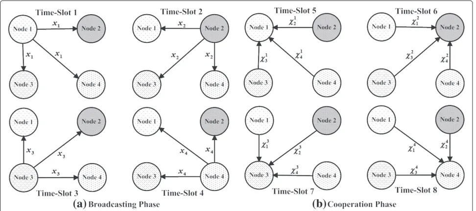
The cooperative communication between all the nodes (depicted in Figure 1 forN =4) is performed over a total of 2Ntime slots and is split into two phases (Ntime slots each): (a) the broadcasting phase (BP) and (b) the coop-eration phase (CP). The communication under the two phases will be detailed in the following subsections and is expressed in matrix form as
S1 · · · Sj · · · SN S1 · · · Si · · · SN
In the broadcasting phase, a source nodeSj is assigned
a time slotTj in which it broadcasts its own data
sym-bol xj to the N −1 other nodes Si in the network for i ∈ {1, 2,. . .,N} for i = j. For source separation at each receiving node, each transmitted symbolxjis spread
using a signature waveform cj(t) where it is assumed
that each node knows the signature waveforms of all the other nodes. The cross-correlation of cj(t) and ci(t) is
ρj,i = cj(t),ci(t) (1/Ts)0Tscj(t)ci∗(t)dt forj = i, with
ρj,j=1 andTsbeing the symbol duration. Thus, the signal
received at nodeSifori=jin time slotTjis expressed as
yj,i(t)=
PBjhj,ixjcj(t)+nj,i(t), (2)
wherePBj is the transmit power in the broadcasting phase at nodeSj, andhj,iis the Rayleigh flat fading channel
coef-ficient between nodesSjandSi. Also,nj,i(t)is the additive
noise process at node Si due to the signal transmitted
by nodeSj, modeled as a zero-mean complex Gaussian
random variable with varianceN0. To extract data
sym-bolxj at nodeSi, the received signalyj,i(t)(given in (2))
is cross-correlated with the signature waveform cj(t) to
obtain
yj,i= yj,i(t),cj(t) =
PBjhj,ixj+nj,i, (3)
where nj,i ∼ CN(0,N0). Upon completion of the
broadcasting phase, each node Si will have exchanged
its data symbol xi with the other nodes and received
a set of N − 1 signals {yj,i}Nj=1,j=i comprising symbols x1,. . .,xi−1,xi+1,. . .,xNforj=ifrom all the other nodes
in the network. NodeSithen performs a matched
filter-ing operation on each of the received signalsyj,i, and the
signal-to-noise ratio (SNR) at the output of the matched filter is expressed as [2]
γBP
j,i =
PBj|hj,i|2
N0
. (4)
The received signals at each node at the end of the broadcasting phase are expressed as
Y=
where theith row represents the signals received at node Si, while thejth column represents the signals received in
time slotTjfrom nodeSj.
2.2 Cooperation phase
The cooperation phase involves two operations: (1) signal transmission and (2) multinode signal detection, which are discussed in the following subsections, respectivelya.
2.2.1 Signal transmission
In the cooperation phase, each node Si acts as the
des-tination node in time slotTN+i fori ∈ {1, 2,. . .,N}and
receives simultaneous transmissions from the otherN−1 nodes. In particular, each node Sk withk = i forms a
linearly coded signalXki(t)which is composed from the receivedN−2 signals of thekth row of matrixYYY in (5), excluding the received signal from nodeSi. NodeSkthen
Figure 1M2M-STNC scheme withN=4nodes.(a)Broadcasting phase.(b)Cooperation phase.
where cm(t) is the signature waveform associated with
symbol xm, and βm,k,i is the normalization factor, as
defined by [2]
βm,k,i=
Pm,k,iC PB
m|hm,k|2+N0. (7)
From (6), it should be noticed that node Sk relays the
received signals from the otherN−2 nodes. Moreover, the received signal at nodeSiduring time slotTN+iis given by
Yi(t)= N
k=1,k=i
hk,iXki(t)+wi(t)= N
m=1,m=i
αm,ixmcm(t)+ ¯wi(t), (8)
whereαm,iis defined as
αm,i=
PB m
N
k=1 k=i,k=m
βm,k,ihm,khk,i. (9)
In (8),wi(t)is the zero-meanN0variance additive noise
process at nodeSi, andw¯i(t)is the equivalent noise term
which can be expressed as
¯
wi(t)=wi(t)+ N
m=1,m=i N
k=1 k=i,k=m
βm,k,ihk,inm,k(t)cm(t).
(10)
The total power at source node Sm associated with
exchanging symbolxmwith the otherN−1 nodes in the
network is given byPm = PBm+PmC, wherePBm = δmBPm
is the broadcast power andPCm = Ni=1,i=mPCm,i = δmCPm
is the total cooperative power, with 0 < δB
m ≤ 1 and δC
m = 1 − δmB being the power allocation fractions to
the broadcasting and cooperation phases, respectively. In addition, PCm,i is the total cooperative power associated with relaying symbolxmto destination nodeSifori=m
such thatPCm,i = δCm,iPCmwith 0≤ δCm,i ≤ 1. Thus,Pm,iC is given byPCm,i = Nk=1
k=i,k=m
PCm,k,iwith each relaying node
Skfork=mandk=ibeing allocated cooperative power
PCm,k,i=δCm,k,iPCm,iwith 0≤δCm,k,i≤1. Without any loss of
generality, it is assumed that all the transmit power asso-ciated with transmitting symbolxmis the same for all the Nnodes (i.e.,Pm=P=PBm+PCm,∀m∈ {1, 2,. . .,N}).
2.2.2 Multinode signal detection
Upon receiving signalYi(t), a multinode signal detection
operation is performed by nodeSito extract each of the N−1 symbolsxj, forj∈ {1, 2,. . .,N}j=i. This is achieved
by passing the received signal Yi(t) through a matched
filter bank (MFB) of N − 1 branches, matched to the corresponding nodes’ signature waveformscj(t), yielding
Yj,i= Yi(t),cj(t) = N
m=1,m=i
αm,ixmρm,j+ ¯wj,i, (11)
where ρm,j is the correlation coefficient between cm(t)
and cj(t). The output of the MFB can be put in a
vec-tor form of all the N−1 Yi,j’s signals asYYYi =RRRiAAAixxxi +
¯
w¯ w¯
wi, where YYYi =
Y1,i,. . .,Yi−1,i,Yi+1,i,. . .,YN,i
T
, and xxxi = [x1,. . .,xi−1,xi+1,. . .,xN]T. In addition, www¯¯¯i =
¯
w1,i,. . .,w¯i−1,i,w¯i+1,i,. . .,w¯N,i
T∼CN(0
andRRRi,AAAiandI,GGGiare(N−1)×(N−1)matrices withI
being the identity matrix withRRRibeing defined as
R
and the diagonal matrices AAAi and GGGi are, respectively,
written as The received signal vectorYYYi can then be decorrelated
(assuming matrixRRRiis invertible) asYYY¯¯¯i =RRR−i1YYYi=AAAixxxi+
Thus, at node Si, the decorrelated received signal Y¯j,i
corresponding to symbolxjis obtained as
¯
diagonal element of matrixRRR−i 1. Without loss of general-ity, it is assumed thatρj,i = ρ for allj = iand thus [6]
j,i=
1+(N−3)ρ
1+(N−3)ρ−(N−2)ρ2 N−1. (16)
It should be noted that upon the completion of the broad-casting and cooperation phases, each node Si for i =
1, 2,. . .,Nhas receivedN−1 signals containing symbolxj
forj=1, 2,. . .,Nandj=i; a direct signal from the source nodeSjin the broadcasting phase andN−2 signals from
nodesSmform=iandm=j, in the cooperation phase.
The instantaneous SNR at the output of the matched filter at nodeSicorresponding to symbolxjis given by
γj,i=γj,iBP+γj,iCP, (17)
whereγj,iBPis an exponential random variable as in (4) with meanλBPj,i = N0
It is clear from (18) thatγj,iCP is adversely affected by the noise amplification due to the simultaneous transmissions of theN−2 nodes. The achievable rate between source nodeSjand destination nodeSiis given by
RM2M-STNC
and the total achievable rate by node Sj is expressed
as RM2M-STNCj = Ni=1,i=jRM2M-STNCj,i γj,i. It should
be noted that the M2M-STNC scheme requires strin-gent timing synchronization between the relaying nodes, and synchronizing all the distributedNnodes, as will be discussed later in this paper, is practically prohibitive.
3 Space-time network coding with optimal node selection
When nodeSi acts as a destination node in its assigned
time slotTN+i, the intermediate node the transmitted
sig-nal of which results in the highest cumulative SNR value for symbolxm of source nodeSm form = iis selected.
Specifically, for each source node, optimal relaying nodes are selected and then all the nodes selected for at least one source node transmit simultaneously. The node selection metric used by the destination nodeSito determine the
optimal nodeSkto ‘relay’ symbolxmreceived from source
nodeSm fork = iand k = m is based on thescaled
harmonic mean of the instantaneous source, intermediate and destination nodes’ scaled channel gains, as followsb [15,20,21]
broadcast transmission of symbol xm from source node Smto intermediate nodeSkwith transmit powerPBmand
the cooperative transmission of symbol xm from
inter-mediate node Sk to the destination node Si with
coop-erative transmit power PCm,k,i = PCm,i. Thus, the scaled harmonic mean values corresponding to symbolxm, for m = i at node Sk fork = i and k = m when node Si is the destination node is summarized in a matrix
form as
mally selected node to forward symbol xm among the N−2 nodes that received independent copies of symbol xm during the broadcasting phase is defined by km,iopt =
arg maxk=1,2,...,N{γm,k,i}k=i,k=m. Hence, in time slotTN+i
for each symbol xm form = i, the system reduces to a
source nodeSm, a destination nodeSi, and an optimally
selected node for the transmission ofxm. Thus, each
sym-bol xm is associated with a set of indicator functions in
the form of Im,i = {Im,k,i}Nk=1,k=i,k=m, whereIm,k,i for k = i,k = m acts as a binary indicator function when nodeSi is the receiving node, while Sk is the optimally
selected node transmitting signal ym,k corresponding to
symbolxm. Hence,Im,k,i is defined byIm,k,i = 1 ifk = km,iopt; otherwise,Im,k,i=0.
As before, each nodeSk then possibly forms a linearly
coded signalZki(t)from its received signals in the broad-casting phase and transmits it to nodeSiduring time slot TN+i. Specifically,Zki(t) is composed from the received
It should be noted that if nodeSkis not an optimal node
to forward any of thexmform=i,m=kdata signals to
nodeSi, thenZki(t)=0; otherwise, nodeSkis an optimal
node to forward at least one symbolxm andZki(t) = 0.
Following the steps of the previous section, the received signal at nodeSiduring time slotTN+iis given by
with h¯m,opt,i being the channel coefficient between the
source node Sm and the optimally selected node to
for-ward symbol xm to node Si for m = i, as implied by k = km,iopt, andβm,opt,i is the scaling factor defined in (7).
Also,hˆm,opt,i is the channel coefficient between the
opti-mally selected node and nodeSi for the transmission of
symbolxmform=i. In (23),wˆi(t)is the equivalent noise
term which can be expressed as
ˆ
wherenm,opt,iis the noise sample at the optimally selected
node by node Si for the transmission of symbolxm, for m = i. It should be noted that under the M2M-STNC-ONS scheme, the total cooperative transmit power associ-ated with relaying symbolxmto nodeSiis set toPCm,opt,i= PCm,i = δCm,iPCm, where PCm,opt,i is the cooperative trans-mit power allocated to the optimally selected node. Thus, the total power associated with transmitting symbolxmis
given byP=PBm+iN=1,i=mPCm,opt,i.
To extract symbolxj, the received signalYˆi(t)is passed
through a MFB, and the output of the jth branch is expressed asYˆj,i = Nm=1,m=iαˆm,ixmρm,j+ ˆwj,i which in
The decorrelated signalYˆj,iis given by
first comes from the direct transmission in the broadcast-ing phase, while the other is from the optimally selected node in the cooperation phase. At the output of the matched filter, the instantaneous SNR is given by
ˆ
which at high SNR can be tightly approximated as [2]
¯ˆ
where it can be verified thatγ¯ˆj,iCPis the scaled harmonic mean of two exponential random variables
Xj,optB = P
tively. Note thatγ¯ˆj,iCPcorresponds to the optimally selected node with the maximum harmonic mean. The means of γBP
j,i + ¯ˆγj,iCP. The achievable rate between source node Sj and destination node Si under the M2M-STNC-ONS
scheme is given by
RM2M-STNC-ONS
the total rate achievable by nodeSj.
4 Symbol error rate performance analysis
4.1 M2M-STNC
In general, the SER for M-PSK modulation conditional on the channel state information (CSI) for SNRγ is given by [22]
|{h}(γ )= π1
where bpsk = sin2(π/M). The derived instantaneous
SNR due to the cooperative transmissionγj,iCP in (18) is
extremely difficult to manipulate [5]. Thus, only the con-ditional SER of symbolxjdetected at nodeSi(fori=j) is
provided, which can be evaluated numerically as
PM2M-STNCSER =|{h
Denoting the moment generating function (MGF) of a random variableZwith probability density function (PDF) pZ(z)as
and averaging the conditional SER over the Rayleigh fad-ing channel statistics, the approximate SER expression is given by
To determine the MGF of γ¯ˆj,iCP, the cumulative distribution function (CDF) ofγ¯ˆj,iCPis derived as
PγˆCP
toPγˆj,k,i(γ ) ≈ 1−e
−γλˆB j,k+ˆλCj,k,i
. For convenience, define ˆ
Therefore, the PDF ofγ¯ˆj,iCPcan be obtained as
pγ¯ˆCP
(42) to determine the MGF ofγ¯ˆj,iCP is quite difficult [20]; however, a useful relationship between the CDF of a random variable X and its MGF exists and is given by MX(s) = sL{PX(x)}, withL{·}being the Laplace
trans-form of the parameter CDF [23]. Hence, by substituting
Pγˆj,k,i(γ ) ≈ 1 − e
−γλˆB j,k+ˆλCj,k,i
into (39), expanding the resulting product and then taking the Laplace transform, the MGF ofγ¯ˆj,iCPcan be shown to be
Thus, by substituting (38) and (43) into (37), the approx-imate SER performance for symbolxjdetected at nodeSi
fori=jcan be determined using
˜
PSERM2M-STNC-ONS≈ 1
π
4.2.1 Asymptotic upper bound
An asymptotic upper bound on the SER performance is derived by first noticing that at high SNR, the MGF ofγj,iBP given in (38) can be asymptotically upper bounded as [2]
MγBP j,i (s)
N0
sδBjPσj2,i. (45)
Second, an asymptotic upper bound forMγ¯CP
j,i (s)at high
it can be shown that
Mγ¯ˆCP
Finally, by substituting (45) and (47) into (37), the asymp-totic upper-bound SER expression is obtained as
¯
PUB-SERM2M-STNC-ONS N0 P
4.2.2 Diversity order analysis
The diversity order is given by = −limSNR→∞
logP¯UB-SERM2M-STNC-ONS/log(SNR), where SNR = P/N0
[2]. Clearly, the M2M-STNC-ONS scheme achieves a full diversity order of=N−1 per node.
It is noteworthy that the concept of many-to-many space-time network coding with optimal node selection allows us to achieve full diversity ofN −1 per network node with only 2N time slots. In conventional TDMA-based cooperative communications (i.e., without network coding and multiple-access transmissions), a total of N2 time slots is required to achieve full diversity. Clearly, our scheme is more bandwidth efficient than conventional cooperative communication systems.
5 Timing synchronization analysis
simultaneous transmissions of the different nodes during the cooperation phase impose a major practical challenge, especially for a large number of the transmitting nodes distributed over a large network area. Clock mismatches of the geographically distributed nodes result in different transmission times. Also, the lack of tracking at the receiv-ing node for all the other cooperative nodes and the lack of compensation for propagation delays can have detrimen-tal effects on the network performance. Thus, this section aims at analyzing the degradation in the SER performance of the M2M-STNC and M2M-STNC-ONS schemes due to the timing offsets between the nodes in the cooperation phase.
5.1 Signal model under M2M-STNC scheme
In the cooperation phase, consider the scenario where node Si is the receiving node while the remaining
dis-tributed nodes Sm for m ∈ {1, 2,. . .,N}m=i transmit
asynchronously. Letτi,mbe the time offset for each
trans-mitting nodeSmduring theith time slot. Also, assume that
each distributed node initiates and terminates its trans-missions withinTs time units of each other within each
TDMA time slot. Moreover, the effect of the different propagation delays is manifested in the form of superposi-tion of pulses from each nodeSmform∈ {1, 2,. . .,N}m=i
that are shifted byτi,m. This implies that neighboring
sym-bols will introduce intersymbol interference (ISI) to the desired symbol. In this work, only the ISI contribution from the neighboring symbols to the desired symbol is considered, while higher-order terms are neglected due to their smaller effect [14]. From (8), the received signal at nodeSiduring theith time slot is expressed asc[25,26]
Yi(t)=
Without loss of generality, the random time shifts between theN−1 nodes and the receiving nodeSiare ordered such
that 0 ≤ τi,1 ≤ . . . ≤ τi,i−1 ≤ τi,i+1 ≤ . . . ≤ τi,N < Ts.
As before, the received signal is then fed into a bank of (N − 1) filters, matched to the nodes’ signature wave-forms, and sampled at t = lTs + i, wherei is the
timing shift chosen by the receiving nodeSito compensate
for the average delay of the transmitting nodes. Thus, the received signal is given by [27]
Yj,i(n)=Yi(t),cj(t)=
Furthermore, the time shifts are assumed to be uniformly distributed as(τi,m−i) ∼ U[−Ts/2,Ts/2] around
the reference clock i, ∀m ∈ {1, 2,. . .,N}m=i, where Ts∈[0,Ts)is the maximum time-shift value. Intuitively,
andRRRi(1) =RRRTi (−1) = ˜RRR˜˜i, whereRRR˜˜˜iis defined as follows
Thus, the output of the matched filter bank can be expressed as [27,29]
Y
YYi(l)= ˜RRR˜˜Ti AAAixxxi(l+1)+ ¯RRR¯¯iAAAixxxi(l)+ ˜RRR˜˜iAAAixxxi(l−1)+ ¯www¯¯i(l),
(57)
where matrixAAAi is defined in (13), whereasxxxi(l+ς)is
defined in general as
xxxi(l+ς)=[x1(l+ς),. . .,xi−1(l+ς),
The decorrelated received signalY¯j,i(l)at the output of the jth MFB branch is given by
where ρ¯¯j,j, is the jth diagonal element of matrix RRR¯¯¯¯¯¯i, the above analysis, the instantaneous conditional signal-to-interference-plus-noise ratio (SINR) at the output of the MRC of nodeSi of symbolxjforj = i, after further
manipulation, is obtained as
γj,i=γj,iBP+ ˆγj,iCP=
whereIj,iis the ISI variance as defined by
Ij,i=
and it is assumed that the data symbols are statistically independent. Based on (62), finding a closed form solution for the SER for M-PSK modulation is extremely difficult; therefore, a conditional SER given the channel knowl-edge is obtained by substituting (62) into (34) and then numerically evaluating it.
It should be noted that γj,i in (62) is composed of the
per-5.2 Signal model under M2M-STNC-ONS scheme From (23), the received signal at nodeSiis given by
ˆ
Following the analysis of the M2M-STNC scheme and replacing matricesAAAiandGGGiwithAAAˆˆˆi andGGGˆˆˆi, respectively
(see (26) and (27)), the instantaneous conditional SINR of symbolxjat nodeSican be shown to be
where ˆˆj,i is the jth diagonal element of matrix R
It is noteworthy that under perfect timing synchroniza-tion, (66) reduces to (29), as the SINR term due to the cooperation phase reduces to the SNR term of (30).
6 Imperfect channel state information
So far, perfect CSI has been assumed and in prac-tice, such assumption is not valid. Channel estimation errors are possibly caused by inaccurate channel estima-tion/equalization, noise or Doppler shift. Conventionally, channel estimation is based on transmitting a known pilot ‘training’ sequence with a particular power, prior to data transmission. Inaccurate channel estimation results in a channel estimation error with variance, denoted asε. At the end of the training phase, the receiving node has imperfect CSI for channel equalization and data detec-tion. In the following subsections, the impact of channel estimation errors on the performance of the M2M-STNC and M2M-STNC-ONS schemes, assuming perfect timing synchronization, is studied and characterized.
6.1 M2M-STNC
In the broadcasting phase, the received signal at nodeSi
from nodeSjwith channel estimation error is expressed as
yεj,i(t)=
PBj(hj,i+hεj,i)xjcj(t)+nj,i(t), (68)
where hεj,i denotes the channel estimation error.
Conse-quently,
PBjhεj,ixj is the added noise term that scales
with the broadcasting power. Furthermore, the channel estimation error hεj,i is modeled as a zero-mean com-plex Gaussian random variable with variance εj,i. Thus,
the additional self-noise term
PBjhεj,ixj is a zero-mean
complex Gaussian random variable with varianceεj,iPBj.
Equation (68) is re-written as
yεj,i(t)=
after matched filtering is given by
γBP
j,i =
PBj|hj,i|2 εj,iPBj +N0
. (70)
In the cooperation phase, the received signal at nodeSiis
¯
After multinode signal detection, the received signal corresponding to symbolxjis given by
¯
In turn, the SNR at the output of the matched filter of nodeSiis expressed as
γCP
Based on (70) and (77), it is clear that channel estimation errors increase the noise variance, which in turn reduces the resulting SNR at the output of the matched filter. Thus, with channel estimation errors, increasing the broadcasting and/or transmit power cannot indefinitely increase the SNR. Additionally, in the case of perfect CSI (i.e.,εj,i = 0,
∀j,i∈ {1, 2,. . .,N}, andj=i), then the SNR expressions in (70) and (77) reduce to (4) and (18), respectively.
6.2 M2M-STNC-ONS
Under the M2M-STNC-ONS schemed, the received signal (see (23)) in the cooperation phase at nodeSiis given by
ˆ
Moreover,wˆεi(t)is equivalent interference plus noise term, defined as
ˆ
Following (28), the decorrelated signal can be obtained as
ˆ
ˆ
γCP j,i =
PjBPjC,i|¯hj,opt,i|2|ˆhj,opt,i|2
N−1
N0
PBj |¯hj,opt,i|2+¯εj,opt,i
+PjC,i|ˆhj,opt,i|2+ˆεj,opt,i
+N0
+PjC,i|ˆhj,opt,i|2ε¯j,opt,i+|¯hj,opt,i|2εˆj,opt,i+ˆεj,opt,iε¯j,opt,i
,
(83)
where it should be noted that in the perfect CSI case, the SNR expression in (83) reduces to that of (30). Finally, by comparing (77) and (83), it can be seen that the SNR term in (83) is affected only by the channel estimation errors of the channels between nodeSj, the optimally selected
node, and the destination nodeSi, rather than the
chan-nels between nodeSjand all the other intermediate nodes
as well as nodeSi, forj=i.
7 Performance evaluation
In this section, the analytical derivations of the SER and achievable rate performance of the M2M-STNC and M2M-STNC-ONS schemes are evaluated and compared for node S1’s symbol x1 received at node S4. Equal
power allocation between the two transmission phases is assumed, such thatPB
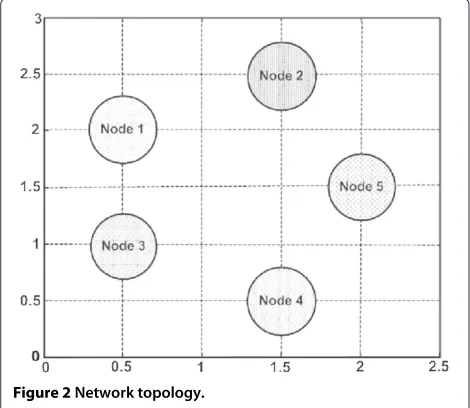
1 =PC1 =P/2,P1,iC =PC1/(N−1)= P/(2(N−1)),∀i∈ {2,. . .,N}andP1,k,iC =P1,iC/(N−2)= P/(2(N− 1)(N −2)),∀k ∈ {2,. . .,N} andk = i. The network nodes are located as shown in Figure 2 with the channel variance between nodesSj andSi being defined
ashj,i ∼ CN(0,d−j,iν),∀j,i ∈ {1, 2,. . .,N} for j=i and ν=3. Non-orthogonal signature waveforms with a cross-correlation ofρj,i = ρ = 0.5 forj = iare also assumed.
The channel estimation error variance is assumed to be the same between any two nodes (i.e., εj,i = ε,∀j,i ∈
{1, 2,. . .,N}forj=i).
To verify the achievable diversity order, consider the following cases. When N = 3, the network consists of nodes S1, S3, and S4 (i.e., S2 and S5 are inactive). In
Figure 2Network topology.
this case, only nodeS3relays symbolx1to node S4. As
for N = 4, all network nodes but node S5 are active.
Hence, nodesS2andS3act as relays for nodeS1. Lastly,
forN = 5, all network nodes are active, in which case nodesS2,S3, andS5forward symbolx1to nodeS4. Now,
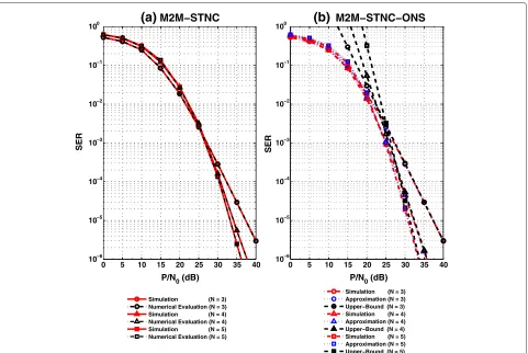
from Figure 3 and assuming perfect timing synchroniza-tion and CSI, it is clear that as the number of cooperating nodesN in the network increases, the SER performance of both schemes improves which is due to the increased diversity order achievable with the increase inN. Also, for N = 3, both schemes yield the same SER performance. Moreover, the numerically evaluated SER performance of the M2M-STNC scheme (see Figure 3a) perfectly agrees with its simulated performance. In addition, the SER per-formance of proposed the M2M-STNC-ONS scheme (see Figure 3b) outperforms that of its counterpart forN = 4 and N = 5. Furthermore, the derived approximate SER theoretical expression under the M2M-STNC-ONS scheme coincides with the simulated performance except for a slight deviation at low SNR which is attributed to the approximation used in the theoretical analysis that assumed high enough SNR. Also, the derived upper bound happens to be asymptotic at high SNR and thus confirms the achievable diversity order per node.
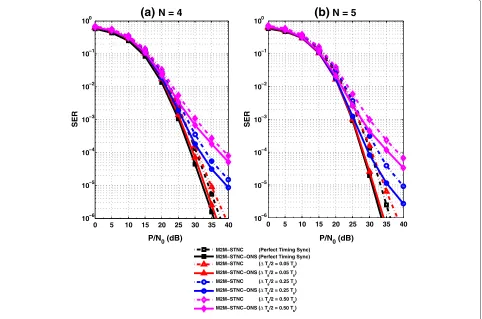
From this point onwards, only the cases of N = 4 and N = 5 are considered. Now, in Figure 4a, the SER performance of the M2M-STNC and M2M-STNC-ONS schemes is compared with timing synchronization errors and perfect CSI forN = 4 nodes. It is clear that the M2M-STNC-ONS scheme is more resistant to tim-ing offsets than its counterpart scheme. This is because the number of simultaneous transmissions in each time slot is reduced, and only the node achieving the highest cooperative SNR at the receiving node relays its received signal. A similar observation can be seen in the case of N = 5 nodes (see Figure 4b). However, it is noticed that the impact of timing offsets on the SER performance is less severe despite the increase in the number of transmitting nodes. This is again due to the increased diversity order.
0 5 10 15 20 25 30 35 40 10
10 10 10 10 10 10
P/N0 (dB) P/N0 (dB)
SER
(a)
M2M−STNC0 5 10 15 20 25 30 35 40 10−6
10−5 10−4 10−3 10−2 10−1 100
−6 −5 −4 −3 −2 −1 0
SER
(b)
M2M−STNC−ONSSimulation (N = 3) Numerical Evaluation (N = 3) Simulation (N = 4) Numerical Evaluation (N = 4) Simulation (N = 5) Numerical Evaluation (N = 5)
Simulation (N = 3) Approximation (N = 3) Upper−Bound (N = 3) Simulation (N = 4) Approximation (N = 4) Upper−Bound (N = 4) Simulation (N = 5) Approximation (N = 5) Upper−Bound (N = 5)
Figure 3QPSK SER performance of the (a) M2M-STNC and (b) M2M-STNC-ONS schemes - perfect timing synchronization and CSI.
channel estimation errors due to the increased diversity gains, as aforementioned.
In Figure 6a, the achievable rate of node S1 at node S4forN = 4 nodes is illustrated. It is evident that the
proposed M2M-STNC-ONS scheme with perfect timing synchronization and CSI achieves a better rate than the M2M-STNC scheme. In general, the achievable rate of nodeS1at nodeS4whenN=5 (see Figure 6b) is less than
that whenN = 4, which is due to the increased number of time slots required for communication between all the nodes. The same observation holds for the different cases of perfect/imperfect timing synchronization and CSI.
Figure 7 illustrates the total achievable rate of source nodeS1forN = 4 andN = 5 node networks. It is clear
that the proposed M2M-STNC-ONS scheme is superior to the M2M-STNC scheme, and the total achievable rate for a network with N = 5 is higher than that of a net-work withN=4, despite the decrease in the rate between nodeS1and all the other nodes in the networks. Finally,
the gain in rate of the M2M-STNC-ONS scheme com-pared with its counterpart M2M-STNC scheme is higher for the network with N = 5 nodes. This again can be seen from the different cases of perfect/imperfect timing synchronization and CSI.
8 Conclusions
0 5 10 15 20 25 30 35 40 10−6
10−5 10−4 10−3 10−2 10−1 100
P/N0 (dB) P/N0 (dB)
SER
10−6 10−5 10−4 10−3 10−2 10−1 100
SER
(a)
N = 4M2M−STNC (Perfect Timing Sync) M2M−STNC−ONS (Perfect Timing Sync) M2M−STNC (ΔT /2 = 0.05 T ) M2M−STNC−ONS (ΔT /2 = 0.05 T ) M2M−STNC (ΔT /2 = 0.25 T ) M2M−STNC−ONS (ΔT /2 = 0.25 T ) M2M−STNC (ΔT /2 = 0.50 T ) M2M−STNC−ONS (ΔT /2 = 0.50 T )
0 5 10 15 20 25 30 35 40
(b)
N = 5Figure 4QPSK SER performance with timing synchronization errors for (a)N=4and (b)N=5nodes - perfect CSI.
0 5 10 15 20 25 30 35 40 10−6
10−5 10−4 10−3 10−2 10−1 100
10−6 10−5 10−4 10−3 10−2 10−1 100
P/N0 (dB) P/N0 (dB)
SER
(a)
N = 40 5 10 15 20 25 30 35 40
SER
(b)
N = 5M2M−STNC (Perfect CSI) M2M−STNC−ONS (Perfect CSI) M2M−STNC (Imperfect CSI −ε = 0.001) M2M−STNC−ONS (Imperfect CSI −ε = 0.001) M2M−STNC (Imperfect CSI −ε = 0.01) M2M−STNC−ONS (Imperfect CSI −ε = 0.01)
0 5 10 15 20 25 30 35 40 0
0.1 0.2 0.3 0.4 0.5 0.6 0.7 0.8 0.9 1 1.1 1.2 1.3 1.4
P/N0 (dB) P/N0 (dB)
Rate (Bits/s/Hz)
0 0.1 0.2 0.3 0.4 0.5 0.6 0.7 0.8 0.9 1 1.1 1.2 1.3 1.4
Rate (Bits/s/Hz)
(a)
N = 40 5 10 15 20 25 30 35 40
(b)
N = 5M2M−STNC (Perfect Timing Sync and CSI) M2M−STNC−ONS (Perfect Timing Sync and CSI)
M2M−STNC (Perfect CSI with Timing Offsets − ΔT /2 = 0.25 T ) M2M−STNC−ONS (Perfect CSI with Timing Offsets −ΔT /2 = 0.25 T ) M2M−STNC (Perfect Timing Sync with Imperfect CSI −ε = 0.01) M2M−STNC−ONS (Perfect Timing Sync with Imperfect CSI −ε = 0.01) Figure 6Achievable rate of nodeS1at nodeS4for (a)N=4and (b)N=5nodes.
0 5 10 15 20 25 30 35 40 0
0.25 0.5 0.75 1 1.25 1.5 1.75 2 2.25 2.5 2.75 3 3.25 3.5 3.75 4 4.25 4.5
0 0.25 0.5 0.75 1 1.25 1.5 1.75 2 2.25 2.5 2.75 3 3.25 3.5 3.75 4 4.25 4.5
(a)
N = 4P/N0 (dB) P/N0 (dB)
Rate (Bits/s/Hz)
0 5 10 15 20 25 30 35 40
(b)
N = 5Rate (Bits/s/Hz)
M2M−STNC (Perfect Timing Sync and CSI) M2M−STNC−ONS (Perfect Timing Sync and CSI)
mitigates the effects of noise amplification, timing offsets, and channel estimation errors.
Endnotes
aIt should be noted that our many-to-many space-time
network coding scheme is a CDMA-like system that operates under conventional TDMA by assigning each network node a signature waveform for single- or multiple-access transmission. Signature waveforms provide immunity against various kinds of noise and multipath distortion, and they are important for multiuser transmission/detection and timing/frequency synchronization at the receiving nodes.
bNode selection is achieved via control messages
exchange prior to the cooperation phase [30] and is only updated when the respective channels’ coherence time elapses.
cIt is assumed that the channel coefficients are time
invariant during each time slot but are randomly time varying from one time slot to another.
dThe node selection criterion is now based on the
channel coefficients with estimation errors, which implies that the selected node with imperfect CSI is not necessarily the selected node under perfect CSI.
Competing interests
The authors declare that they have no competing interests.
Author details
1Electrical Engineering Department, College of Engineering and Petroleum,
Kuwait University, Safat 13060, Kuwait.2Wireless @ Virginia Tech, Bradley Department of Electrical and Computer Engineering, Virginia Tech, Blacksburg, VA 24061, USA.
Received: 8 November 2013 Accepted: 12 March 2014 Published: 26 March 2014
References
1. R Ahlswede, N Cai, SY Li, RW Yeung, Network information flow. IEEE Trans. Inform. Theory46, 1204–1216 (2000)
2. KJR Liu, AK Sadek, W Su, A Kwasinski,Cooperative Communications and Networking(Cambridge University Press, Cambridge, 2008)
3. HQ Lai, AS Ibrahim, KJR Liu, Wireless network cocast: location-aware cooperative communications using network coding. IEEE Trans. Wireless Commun.8, 3844–3854 (2009)
4. T Wang, GB Giannakis, Complex field network coding for multiuser cooperative communications. IEEE J. Selected Areas Commun. 26, 561–571 (2008)
5. HQ Lai, KJR Liu, Space-time network coding. IEEE Trans. Signal Process. 4, 1706–1718 (2011)
6. MW Baidas, HQ Lai, KJR Liu, Many-to-many communications via space-time network coding. Paper presented at the IEEE wireless communications and networking conference, Sydney, Australia, 18–21 April 2010, pp. 1–6
7. ZZ Gao, HQ Lai, KJR Liu, Differential space-time network coding for multi-source cooperative communications. IEEE Trans. Commun. 59, 3146–3157 (2011)
8. ZZ Gao, YH Yang, KJR Liu, Anti-eavesdropping space-time network coding for cooperative communications. IEEE Trans. Wireless Commun. 10, 3898–3908 (2011)
9. W Guan, KJR Liu, Clustering based space-time network coding. Paper presented at the IEEE global communications conference (GLOBECOM), Anaheim, CA, USA, 3–7 Dec 2012, pp.5633–5638
10. A Yang, Z Fei, N Yang, C Xing, J Kuang, Symbol error rate of space-time network coding Nakami-m fading. IEEE Trans. Vehicular Technol. 62, 2644–2655 (2013)
11. JN Laneman, GW Wornell, Distributed space-time coded protocols for exploiting cooperative diversity in wireless networks. IEEE Trans. Inform. Theory49, 2415–2425 (2003)
12. L Venturino, X Wang, M Lops, Multiuser detection for cooperative networks and performance analysis. IEEE Trans. Signal Process. 54, 3315–3329 (2006)
13. S Wei, Diversity-multiplexing tradeoff of asynchronous cooperative diversity in wireless networks. IEEE Trans. Inform. Theory53, 4150–4172 (2007)
14. AS Ibrahim, KJR Liu, Mitigating channel estimation error with timing synchronization tradeoff in cooperative communications. IEEE Trans. Signal Process.58, 337–348 (2010)
15. Y Jing, H Jafarkhani, Single and multiple relay selection schemes and their achievable diversity orders. IEEE Trans. Wireless Commun.8, 1414–1423 (2009)
16. Y Zhao, R Adve, TJ Lim, Improving amplify-and-forward relay networks: optimal power allocation versus selection. IEEE Trans. Wireless Commun. 6, 3114–3123 (2007)
17. C Sun, W Zhang, KB Letaief, Cluster-based cooperative spectrum sensing in cognitive radio systems. Paper presented at the IEEE international conference on communications (ICC), Glasgow, Scotland, 24–28 June 2007, pp. 2511–2515
18. Z Zhou, S Zhou, S Cui, JH Cui, Energy-efficient cooperative communication in a clustered wireless sensor network. IEEE Trans. Vehicular Technol.57, 3618–3628 (2008)
19. A Scaglione, D Goeckel, JN Laneman, Cooperative communications in mobile ad-hoc networks: rethinking the link abstraction. IEEE Signal Process. Mag.23, 18–29 (2006)
20. AS Ibrahim, AK Sadek, W Su, KJR Liu, Cooperative communications with relay-selection: when to cooperate and whom to cooperate with? IEEE Trans. Wireless Commun.7, 2814–2827 (2008)
21. MO Hasna, MS Alouini, End-to-end performance of transmission systems with relays over rayleigh fading channels. IEEE Trans. Wireless Commun. 2, 1126–1131 (2003)
22. MK Simon, MS Alouini, A unified approach to the performance analysis of digital communications over generalized fading channels. Proc. IEEE 86, 1860–1877 (1998)
23. IS Gradshteyn, IM Ryshik,Table of Integrals, Series and Products, 7th. edn. (Academic, New York, 2007)
24. KG Seddik, AK Sadek, AS Ibrahim, KJR Liu, Design criteria and performance analysis for distributed space-time coding. IEEE Trans. Vehicular Technol. 57, 2280–2292 (2008)
25. X Li, YC Wu, E Serpedin, Timing synchronization in decode-and-forward cooperative communication systems. IEEE Trans. Signal Process. 57, 1444–1455 (2009)
26. S Jagannathan, H Aghajan, A Goldsmith, The effect of time
synchronization errors on the performance of cooperative MISO systems. Paper presented at the IEEE global communications (GLOBECOM), Dallas, TX, USA, 29 Nov–3 Dec 2004, pp. 102–107
27. H Elders-Boll, A Bushoom, HD Schotten, Implementation of linear multiuser detectors for asynchronous CDMA systems by linear interference cancellation algorithms. Paper presented at the IEEE vehicular technology conference (VTC), Ottawa, ON, Canada, 18–21 May 1998, pp. 1849–1853
28. KS Kim, I Song, YH Kim, YU Lee, J Lee, Analysis of quasi-ML multiuser detection of DS/CDMA systems in asynchronous channels. IEEE Trans. Commun.47, 1875–1883 (1999)
29. S Verdu,Multiuser Detection(Cambridge University Press, Cambridge, 1998) 30. H Adam, C Bettstetter, SM Senouci, Adaptive relay selection in
cooperative wireless networks. Paper presented at the IEEE international symposium on personal, indoor, and mobile radio communications (PIMRC), Cannes, France, 15–18 Sept 2008, pp. 1–5
doi:10.1186/1687-1499-2014-48