Efficient Dynamic Provable Possession of Remote Data via Update
Trees
Yihua Zhang and Marina Blanton
Department of Computer Science and Engineering University of Notre Dame
{yzhang16,mblanton}@nd.edu
Abstract
The emergence and wide availability of remote storage service providers prompted work in the security community that allows a client to verify integrity and availability of the data that she outsourced to an untrusted remove storage server at a relatively low cost. Most recent solutions to this problem allow the client to read and update (i.e., insert, modify, or delete) stored data blocks while trying to lower the overhead associated with verifying the integrity of the stored data. In this work we develop a novel scheme, performance of which favorably compares with the existing solutions. Our solution enjoys a number of new features such as a natural support for operations on ranges of blocks, revision control, and support for multiple user access to shared content. The performance guarantees that we achieve stem from a novel data structure termed abalanced update treeand removing the need to verify update operations.
1
Introduction
Cloud computing and storage services are commonplace today and enable on-demand access to computing and data storage resources, which can be configured to meet unique constraints of the clients and utilized with minimal management overhead. The recent rapid growth in availability of cloud services makes such services attractive and economically sensible for clients with limited computing or storage resources who are unwilling or unable to procure and maintain their own computing infrastructure. It has been suggested, however, that the top impediment on the way of harnessing the benefits of cloud computing to the fullest extent is security and privacy considerations that prevent clients from placing their data or computations on the cloud (see, e.g., [1]). For that reason, there has been an increased interest in the research community in securing outsourced data storage and computation, and in particular, in verification of remotely stored data.
The motivation for this work comes from (i) improving the performance of the existing schemes when modifications to the data are common, and (ii) extending the available solutions with new features such as support for revision control and multi-user access to shared data. Toward this end, we design and implement a novel mechanism for efficient verification of remotely stored data with support for dynamic operations. Our solution uses a new data structure, which we call a
balanced update tree. The size of the tree is independent of the overall size of the outsourced
storage, but rather depends on the number of updates (modifications, insertions, and deletions) to the remote blocks. The data structure is designed to provide a natural support for handling ranges of blocks (as opposed to always processing individual blocks) and is balanced allowing for very efficient operations. A distinctive feature of our scheme is that all dynamic operations are not followed by integrity verification, which results in substantial communication and computation savings. Instead, verification can be performed at the time of retrieving the data or through periodic challenge queries as in prior work. Verifying a subset of the stored blocks periodically can incur larger overheads than verifying only the data which is being used, but can result in problems being detected earlier.
Today many services outsource their storage to remote servers or the cloud, which can include web services, blogs, and other applications in which there is a need for multiple users to access and update the data, and modifications to the stored data are common. For example, many subscribers of a popular blog hosted by a cloud-based server are allowed to upload, edit, or remove blog content ranging from a short commentary to a large video clip. This demands support for multiple user access while maintaining data consistency and integrity, which current schemes do not provide. In addition to supporting this feature, our solutions provides support for revision control which can be of value for certain applications as well. Because in the existing solutions the server maintains only the up-to-date values of each data block, support for revision control can be added by means of additional techniques (such as [3]), but they result in noticeable overhead per update. In our solution, on the other hand, there is no additional cost for enabling retrieval and verification of older versions of data blocks beyond the obvious need for the server to store them with small metadata. Finally, because the size of the maintained data structure grows with the number of dynamic operations, by issuing a commit command, the client will be able to keep the size of the maintained update tree below a desired constant threshold if necessary.
To summarize, our solution enjoys the following features:
• Improved efficiency in handling dynamic operations. In our solution there is no need to verify integrity of updates (e.g., a data block which is modified a large number of times and is con-sequently deleted), while prior schemes invest resources in verifying correct implementation of each user’s action by the storage server.
• Support for range operations. The natural support and use of range operations allows for additional performance improvement of our scheme compared to the existing solutions. • Balanced data structure. The update tree used for verifying correctness of the stored data
blocks is always balanced regardless of the number and order of dynamic operations on the storage. This results in similar performance for locating information about each data block in the tree and is logarithmic in the size of the tree.
• Size of the maintained data structure. In our solution the size of the maintained update tree is independent of the outsourced data size, while it is linear for other solutions that support dynamic operations. The size of the update tree grows with the number of dynamic operations, but can be reduced by issuing a commit command.
• Support for revision control. We provide natural support for revision control which allows clients to retrieve previous versions of their data and efficiently verify their integrity.
These features come at the cost of increased storage (compared to other schemes) at the client who in our solution maintains the update tree locally. Because the size of the data structure is not large (and is independent of the size of the outsourced data), we believe it is a reasonable tradeoff for other improvements that we achieve. In particular, any PC-based client will not be burdened by the local storage even if it reaches a few MB. Other weaker clients (such as mobile users) and battery-operated devices in particular are power-bound and benefit from the reduced computation in our scheme while still will be able to store the data structure locally.
As another tradeoff, our solution does not provide public verifiability that some of the solutions in the prior literature achieve. Public verifiability allows the client to outsource periodic verification of storage integrity to a third party auditor (who is different from the server). The need to verify correct execution of dynamic operations by the client in such schemes, however, still remains (unless the auditor is replaced by a constantly available intermediary who verifies all operations on behalf of the client). Thus, in most circumstances the client’s overhead in our scheme is still lower than the client’s overhead in other solutions with outsourced periodic integrity verification. We leave public verifiability of our scheme as a direction of future work.
2
Related Work
In this section we review selected PDP/POR schemes from prior literature and their difference with the proposed solution. In particular, we are interested in the schemes that support dynamic operations on outsourced storage.
One line of research [18, 5, 23] relies on so-called sentinels which are outsourced together with the client’s data and are used to verify remotely stored blocks. In the setup phase, the client generates
a predefined number of sentinels, each of which could be a function of κ data blocks (whereκ is a
security parameter) chosen according to a pseudo-random function. The client encrypts all sentinels
and stores them together with the data blocks at a remote server. To invoke verification the ith
time, the client executes a challenge-response protocol with the server, as a result of which the
client is able to verify integrity and availability of the blocks contained in theith sentinel. Besides
having a limited number of audits, a disadvantage of this scheme is in poor performance when
blocks need to be updated. In particular, when the client updates the jth data block, he needs to
retrieve all remaining sentinels which have not yet been consumed by the previous audit queries.
This is because the unused sentinels that cover the jth data block need to be modified based on
the newjth data block to prevent them from being invalidated. Furthermore, in order to prevent
the cloud service provider from learning any mapping between data blocks and sentinels, the client has to retrieve all unused sentinels (regardless of whether they cover the data block being updated or not). This is performed for every update operation and incurs a significant communication and computation overhead.
Another line of research [15, 24, 17, 27] with support for dynamic operations utilizes specialized data structures such as Merkle hash trees [24, 17] or skip lists [15] to organize the data blocks outsourced to a server. When a Merkle hash tree is used, each leaf node corresponds to the hash of an individual data block, and each internal node is assigned a value that hashes the concatenation of its children’s values. The client locally keeps the root value of the tree in order to verify the
correctness of various operations. For example, if the server receives a read request on theith block,
and compares it with the one locally stored. For an update request on the ith block, the client
retrieves the same information as that of the read request on the ith data block. After verifying
the correctness of the received information, the client computes a new root value based on the new
ith block, substitutes it for the previously stored root value, and uses it afterwards.
A disadvantage of Merkle hash tree based solutions is that the tree becomes unbalanced after a
series of insert and delete requests. In particular, a data block insert request at positioniis handled
by locating the (i−1)th block, replacing its node with a newly created one that has two children:
a node for the previously stored (i−1)th and a node for the newly insertedith block. Similarly,
a deletion request is handled by removing the corresponding node from the tree and making its sibling take the place of its parent. As access patterns normally do not span across the stored data
at uniformly random locations, for instance, inserting multiple blocks at the same position i will
result in the height of the tree grow for each inserted data block. Because the tree can become extremely unbalanced over time, there will be a large variance in the time needed to locate different blocks within the data structure.
To mitigate the performance drawback of Merkle hash tree based solutions, [15] develops a
scheme based on a skip list. It extends the original skip list [20] by incorporating label [16] and
rank information to enable efficient authentication of client’s updates. Recall that in a skip list [20]
each node v contains two pointers rgt(v) and dwn(v) used for searching. In [16], each node is
also assigned a label f(v) computed by applying a commutative hash function to f(rgt(v)) and
f(dwn(v)) in a specific order to maintain the commutative property. Maintaining only the label of
the skip list’s start node is sufficient for the client to verify the integrity of various operations (the
verification process is the same as that of Merkle hash tree by considering rgt(n) and dwn(n) as
sibling nodes). To make verification efficient, the authors of [15] integrate rank information into
each node v which is the number of bottom-level nodes reachable from it. This allows for each
update to be verified in expected O(logn) time with high probability, where n is the size of the
skip list. The skip list remains balanced regardless of the client’s access or update patterns. The authors also propose support for variable-sized blocks, which is achieved by handling a number
of fixed size blocks as a single block (in this case, a rank of a node denotes the number of bytes
reachable from it) and performing standard operations on it. While this approach guarantees the integrity of variable-sized data blocks in their entirety, it becomes impossible to verify an individual block upon receiving a request on it. Furthermore, the time to locate a fixed size block is linear in the number of blocks stored in a node, which may dominate the overall time when a node contains a large number of blocks in it.
The original Merkle hash tree and skip list schemes maintain only the most recent copy of data and do not provide the ability to retrieve its previous versions. To incorporate the feature, [3] used a persistent authenticated data structure, which copies the leaf-to-root path for each update and
the path is visited when searching for the updated node. The approach uses O(logn) extra space
for each update, where nis the number of nodes in the data structure.
multiple updates issued on the same range of blocks can be condensed into a single node. Due to its moderate size, the client can maintain the data structure locally, which makes the verification process more efficient. Third, we can specify requirements that define when the data structure should be rebalanced. That is, once the requirement is violated, the tree is re-organized to satisfy the constraint. As an example, the constraint of AVL trees [2] can be used that requires that the heights of a node’s subtrees must differ by at most 1.
As we support multi-user access, in a distributed setting we assume that the users can commu-nicate directly and notify each other of the changes that they make to the repository. There are alternatives to this solution, for instance, the approach employed in SUNDR [19] where the users communicate through an untrusted server (with slightly weaker security guarantees). SUNDR and similar solutions are therefore complimentary to our work.
Prior to this work, the notion of a range tree was used in the database domain to deal with range queries [7]. The range tree data structure, however, is majorly dissimilar to our update trees. For instance, range trees store one record per node as opposed to a range, are static as opposed to be dynamically updated and balanced throughout system operation, etc. One of most significant challenges of this work was to design a update tree that can be rebalanced at low cost after an arbitrary changes to it. A balanced update tree is therefore one of the novel aspects of this work.
3
Problem Definition
We consider the problem in which a resource-limited client is in possession of a large amount of
data partitioned into blocks. Let N denote the initial number of blocks and mi denote the data
block at index i, where 1≤i≤N. The client outsources her data to a storage or cloud server and
would like to be able to update and retrieve her data in a way that integrity of all returned data blocks can be verified. If the data that the client wishes to outsource is sensitive and its secrecy is to be protected from the server, the client should encrypt each data block using any suitable
encryption mechanism prior to storing it at the remote server. In that case, each data block mi
corresponds to encrypted data, and the solution should be oblivious to whether data confidentiality is protected or not. We assume that the client and the server are connected by (or establish) a secure authenticated channel for the purposes of any communication.
The primary feature that we would like a scheme to have is support for dynamic operations,
which include modifying, inserting, or deleting one or more data blocks. We also consider
minimal-overhead support for revision control as a desirable feature to have. This allows the client, in
addition to retrieving the most recent data, to access and verify previous versions of its data, including deleted content. A commit command can be used for a certain range of data blocks to permanently erase previous versions of the data and deleted blocks. Our scheme achieves this property at no extra cost beyond maintaining previous versions by the server, but it is not strictly necessary for a PDP scheme (i.e., the client can run her own revision control system on top of this scheme, but enabling this feature in our scheme lowers the overall overhead).
We define a dynamic provable data possession scheme in terms of the following procedures: • KeyGen(1κ) → {sk} is a probabilistic algorithm run by the client that on input a security
parameter 1κ produces client’s private keysk.
• Init(hsk, m1, . . ., mNi,h⊥i) → {hMCi,hMS, Di} is a protocol run between the client and the
server, during which the client usesskto encode the initial data blocksm1, . . ., mN and store
them at the server who maintains all data blocks outsourced by the client in D. Client’s and
server’s metadata are maintained in MC and MS, respectively.
proto-col run between the client and the server, during which the client preparesnumblocks starting
at index ind and updates them at the server. The operation type op is either modification
(0), insertion (1), or deletion (−1), where no data blocks are used for deletion.
• Retrieve(hsk,MC,ind,numi,hMS, Di) → {hmind, . . ., mind+num−1i,h⊥i} is a protocol run
be-tween the client and the server, during which the client requests num data blocks starting
from index ind, obtains them from the server and verifies their correctness.
• Commit(hsk,MC,ind,num, mind, . . ., mind+num−1i,hMS, Di) → {hM0Ci,hM
0
S, D
0i} is a protocol
run between the client and the server, during which the client re-stores num data blocks
starting from indexindat the server. The server erases all previous copies of the data blocks
in the range and as well as previously deleted by the client blocks that fall into the range if they were kept as part of versioning control.
Our formulation of the scheme has minor differences with prior definitions of DPDP, e.g., as given in [15]. First, update and retrieve operations are defined as interactive protocols rather than several
algorithms run by either the client or the server. Second, in addition to using the Retrieve
proto-col for reading data blocks, in the current formulation it is also used to execute periodic audits. That is, verification of each read is necessary to ensure that correct blocks were received even if the integrity of the overall storage is assured through periodic challenges, and the verification is
performed similar to periodic audits. In particular, because the Retrieve protocol is executed on
a range of data blocks and can cover a large number of blocks, verification is performed proba-bilistically by checking a random sample of blocks of sufficient (but constant) size to guarantee the desired confidence level. (And if the number requested blocks are below the constant, all of them are verified.) This functionality can be easily adopted to implement periodic audits denoted asChallenge(hsk,MCi,hMS, Di)→ {hmi1, . . ., mici,h⊥i}during which a random subset of blocks at
indices i1, . . . , ic is verified. To implement Challenge, we call Retrievec (or fewer if the indices are
adjacent) times on indicesi1, . . . ,ic. We obtain that prior work requires verification for each block
update operation and a constant number of verifications per audit or read request. In our proposed scheme, only read and audit requests need to be verified by checking a constant number of blocks per request.
This constant c can be computed in our and prior work as follows: if num blocks need to be
checked and the server tampers with t of them, the probability that at least one of the verified
blocks matches at least one of the tampered blocks (i.e., the client can detect the problem) is
1 −((num −t)/num)c. This gives us a mechanism for computing c as to achieve the desired
probability of detection for a chosen level of data corruption. For instance, to ensure that if the server tampers 1% or more of the total or retrieved content, the client can detect this with 99%
probability, we need to setc= 460 regardless of the total number of blocks. This means that during
Retrieve orChallengecalls, min(c,num) data blocks need to be verified.
To show security, we follow the definition of secure dynamic PDP from prior literature. In this context, the client should be able to verify the integrity of any data block returned by the server. This includes the verification that the returned data block corresponds to the most recent version of it (or, when revision control is used, a specific previous version, including deleted content, as requested by the client). The server is considered fully untrusted and can modify the stored data in any way it wishes (including deleting the data). Our goal is to design a scheme in which any violations of data integrity or availability will be detected by the client. More precisely, in the single-user setting the security requirements are formulated as a game between a challenger (who
acts as the client) and any PPT adversaryA (who acts as the server):
Setup: the challenger runssk←KeyGen(1κ). The adversary specifies the data blocksm1, . . ., mN
Queries: The adversaryAspecifies what type of a query to perform and on what data blocks. The
challenger prepares the query and sends it to A. If the query requires a response,Asends it
to the challenger, who informs the adversary about the result of verification. The adversary can request any polynomial number of queries of any type, participate in the corresponding protocols, and be informed of the result of verification.
Challenge: At some point,A decides on the content of the storagem1, . . ., mR on which it wants
to be challenged. The challenger prepares a query that replaces the current storage with
the requested data blocks and interacts with A to execute the query. The challenger and
adversary update their metadata according to the verifying updates only (non-verifying up-dates are considered not to have taken place), and the challenger and adversary execute Challenge(hsk,MCi,hMS, Di). If verification ofA’s response succeeds,Awins. The challenger
has the ability to reset A to the beginning of the Challenge query a polynomial number of
times with the purpose of data extraction. The challenger’s goal is to extract the challenged
portions of the data fromA’s responses that pass verification.
When the setting is generalized to multiple users who would like to have access to a shared content, we assume that the users trust each other, but not the server. This implies that the server does not enforce any access control with respect to retrieving or modifying the outsourced data blocks by the users. In environments where access control is to be enforced by a central entity (which could be an organization to which the users belong or a service provider who lets its subscribers to retrieve or modify certain data, while outsourcing the storage to a third party storage provider), the central entity will assume the role of a proxy: it will receive access requests from the users, enforce access control to the storage, submit queries to and verify responses from the storage server, and forward the data to the appropriate user. In the multi-user environment, the security experiment can be defined analogously, where the challenger now represents all users (who mutually trust each other). In the event that the users choose to use different keys for different portions of the outsourced storage (for access control or other purposes), the integrity and retrievability of the data can still be shown using the same security definition, which is now invoked separately for each key.
Besides security, efficient performance of the scheme is also one of our primary goals. Toward that goal, we would like to minimize all of the client’s local storage, communication, and com-putation involved in using the scheme. We also would like to minimize the server’s storage and computation overhead when serving the client’s queries. For that reason, the solution we develop has a natural support for working with ranges of data blocks which is also motivated by users’ sequential access patterns in practice.
In what follows, we first present our basic scheme that works for a single user and does not have full support for revision control. Later we extend it with features of multi-user access and support for revision control in Section 7.
4
Proposed Scheme
4.1 Building blocks
In this work we rely on standard building blocks such as message authentication codes (MAC). A MAC scheme is defined by three algorithms:
1. The key generation algorithmGen, which on input a security parameter 1κ produces a keyk.
2. The tag generation algorithm Mac, which on input keyk and message m ∈ {0,1}∗, outputs
a fixed-length tagt.
3. The verification algorithmVerify, which on input a keyk, messagem, and tagtoutputs a bit
For compactness, we write t ← Mack(m) and b ← Verifyk(m, t). The correctness requirement is
such that for every κ, everyk ← Gen(1κ), and every m ∈ {0,1}∗, Verify
k(m,Mack(m)) = 1. The
security property of a MAC scheme is such that every PPT adversaryAsucceeds in the game below
with at most negligible probability in κ:
1. A random keyk is generated by runningGen(1κ).
2. Ais given 1κ and oracle access to Mack(·). A eventually outputs a pair (m, t). Let Qdenote
the set of all of A’s queries to the oracle.
3. Awins iff both Verifyk(m, t) = 1 andm6∈Q.
4.2 Overview of the scheme
To mitigate the need for performing verifications for each dynamic operation on the outsourced data, in our solution both the client and the server maintain metadata in the form of a binary tree of moderate size. The size of the tree is independent of the number of data blocks that the client outsourced to the server, but grows linearly with the number of updates for ranges of blocks.
We term the new data structure that we build for the purposes of this work a block update
tree. In the update tree, each node corresponds to a range of data blocks on which an update (i.e.,
insertion, deletion, or modification) has been performed. The challenge with constructing such a tree was to ensure that (i) a data block or a range of blocks can be efficiently located within the tree and (ii) we can maintain the tree to be balanced after applying necessary updates caused by client’s queries. With our solution, we obtain that all operations on the remote storage (i.e., retrieve, insert, delete, modify, and commit) involve only work logarithmic in the tree size.
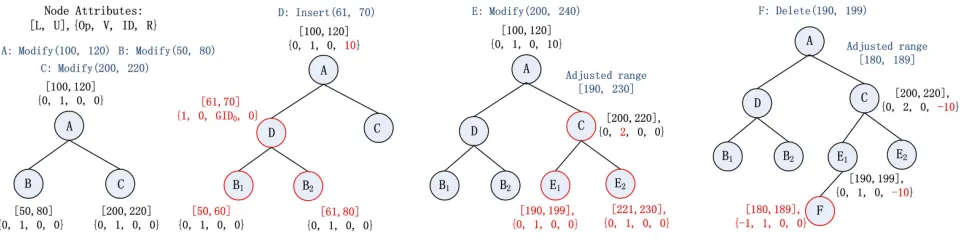
Each node in the update tree contains several attributes, one of which is the range of data
blocks [L,U]. Each time the client requests an update on a particular range, the client and the
server first need to find all nodes in the update tree with which the requested range overlaps (if any). Depending on the result of the search and the operation type, either 0, 1, or 2 nodes might need to be added to the update tree per single-block request. Operating on ranges helps to lower the size of the tree. For any given node in the update tree the range of its left child always covers
data blocks at strictly lower indices than L, and the range of the right child always contains a
range of data blocks with indices strictly larger than U. This allows us to efficiently balance the
tree when the need arises using standard algorithms such as that of AVL trees [2]. Furthermore, because insert and delete operations affect indices of the existing data blocks, in order to quickly determine (or verify) the indices of the stored data blocks after a sequence of updates, we store an
offset valueRwith each node of the update tree which indicates how the ranges of the blocks stored
the tree and the offset of blocks that follow is adjusted accordingly. Then to perform an update (insert, delete, or modify), the client first modifies the tree, computes the MACs of the blocks to be updated, and communicates the blocks (for insertion and modification only) and the MACs to the server. Upon receiving the request, the server also modifies the tree according to the request and stores the received data and MACs. If the server behaves honestly, the server’s update tree will be identical to the client’s update tree (i.e., all changes to the tree are deterministic). To retrieve a range of blocks, the client receives a number of data blocks and their corresponding MACs from the server and verifies their integrity by using information stored in the tree.
4.3 Update tree attributes
Before we proceed with the description of our scheme, we outline the attributes stored with each node of the update tree, as well as global parameters. Description of the update tree algorithms is deferred to Section 5.
With our solution, the client and the server maintain two global counters together with the
update tree,GIDandCID, both of which are initially set to 0. GIDis incremented for each insertion
operation to ensure that each insert operation is marked with a unique identifier. This allows the client to order the blocks that have been inserted into the same position of the file through
different operations. CID is incremented for each commit operation and each commit is assigned
a unique identifier. For a given data block, the combination of its version number and commit ID will uniquely identify a given revision of the block. In addition to global parameters, each node in the update tree stores several attributes:
Node type Op represents the type of operation associated with the node, where values−1, 0, and 1 indicate deletion, modification, and insertion, respectively.
Data block range L,U represents the start and end indices of the data blocks, information about which is stored at the node.
Version number V indicates the number of modifications performed on the data blocks associated with the node. The version number is initially 0 for all data blocks (which are not stored in the update tree), and the version is also reset to 0 during a commit operation for all affected data blocks (at which point information about them is combined into a single node).
Identification number ID of a node has a different meaning depending on the node type. For a
node that represents an insertion, ID denotes the value of GID at the time of the operation,
and for a node that represents a modification or deletion,ID denotes the value ofCIDat the
time of the last commit on the affected data blocks (if no commit operations were previously
performed on the data blocks, the value will be set to 0). In order to identify the type of ID
(i.e., GID or CID) by observing its value, we use non-overlapping ranges to the values from
which IDs for the two different types will be assigned.
Offset R indicates the number of data blocks that have been added to, or deleted from, the range
of data block indices that precede the range of the node (i.e., [0,L−1]). The offset value
affects all data blocks information about which is stored directly in the node as well as all data blocks information about which is stored in the right child subtree of the node.
Pointers Pl and Pr point to the left and right children of the node, respectively, and pointer Pp
points to the parent of the node.
4.4 Construction
In this section, we provide the details of our construction. Because the solution relies on our update tree algorithms, we outline them first, while their detailed description and explanation is given in Section 5.
• UTInsert(T,s,e) inserts a range of new blocks into the update treeT, where the range starts
from index s and consists of (e−s+ 1) data blocks. The function returns a node v that
corresponds to the newly inserted block range.
• UTDelete(T,s,e) marks blocks in the range [s,e] as deleted in the update tree Tand adjusts
the indices of the data blocks that follow. The function returns an array of nodes C from T
that correspond to the deleted data blocks.
• UTModify(T,s,e) updates the version of the blocks in the range [s,e] in the tree T. If some of blocks in the range have not been modified in the past (and therefore are not represented in the tree), the algorithm inserts necessary nodes with version 1. The function returns all
the nodes inT that correspond to the modified data blocks.
• UTRetrieve(T,s,e) returns the nodes in T that correspond to the data blocks in the range
[s,e]. Note that the returned nodes are not guaranteed to cover the entire range as some data
blocks from the range have never been modified.
• UTCommit(T,s,e) removes the nodes in T that correspond to the data blocks in the range
[s,e], balances the remaining tree, and returns an adjusted lower bound andCID.
The protocols that define our solution are as follows:
1. KeyGen(1κ)→ {sk}: the client executessk←Gen(1κ).
2. Init(hsk, m1, . . ., mNi,h⊥i)→ {hMCi,hMS, Di}: the client and the server initialize the update
tree T to empty and set MC = T and MS = T. For each 1 ≤ i ≤ N, the client computes
ti = Macsk(mi||i||0||0||0), where “||” denotes concatenation and the three “0”s indicate the
version number, the CID, and the operation type, respectively. The client sends each hmi, tii
pair to the server who stores this information inD.
3. Update(hsk,MC,op,ind,num, mind, . . ., mind+num−1i,hMS, Di) → {hM0Ci,hM0S, D0i}: the
func-tionality of this protocol is determined by the operation typeopand is defined as follows:
(a) Insert op= 1: the client executesu←UTInsert(MC,ind,ind+num−1).
Delete op=−1: the client executesC ←UTDelete(MC,ind,ind+num−1).
Modify op= 0: the client executes C←UTModify(MC,ind,ind+num−1).
The client stores the updated update tree inM0C.
(b) For each u ∈ C (or a single u in case of insertion), the client locates the data blocks
corresponding to the node’s range from the mi’s, for ind ≤ i ≤ ind+num−1, and
computes ti ← Macsk(mi||u.L+j||u.V||u.ID||op), where j ≥0 indicates the position of
the data block within the node’s blocks. The client sendsop,ind, andnumtogether with
the hmi, tii pairs to the server, with the exception that for delete operations, the data
blocks themselves are not sent.
(c) Insert op= 1: the server executes u←UTInsert(MS,ind,ind+num−1).
Delete op=−1: the server executes C←UTDelete(MS,ind,ind+num−1).
Modify op= 0: the server executes C ←UTModify(MS,ind,ind+num−1).
The server stores the updated update tree in M0S and combines D with received data
(using returned uorC) to obtain D0.
Figure 1: Example of update tree operations.
the operation in its metadata, which will be used for proving the integrity of returned blocks at retrieval time.
4. Retrieve(hsk,MC,ind,numi,hMS, Di)→ {hmind, . . ., mind+num−1i,h⊥i}:
(a) The client sends parametersop,indand numto the server.
(b) The server executesC←UTRetrieve(Ms,ind,ind+num−1). For eachu∈C, the server
retrieves the attribute values from u (i.e.,L,U and pointer to the data blocks), locates
the data blocks and their tags hmi, tiiin D, and sends them to the client.
(c) Upon receiving thehmi, tii, the client executesC←UTRetrieve(MC,ind,ind+num−1).
The client chooses a random subset of data blocks of size min(c,num) for verification
purposes. For each chosen data block mi, the client locates the corresponding u ∈ C
and computes bi ← Verifysk(mi||u.L+j||u.V||u.ID||u.Op, ti), where j is the data block
position within the node’s data blocks. Ifbi = 1 for each verifiedmi, the client is assured
of integrity of returned data.
5. Commit(hsk,MC,ind,num, mind, . . ., mind+num−1i,hMS, Di)→ {hM0Ci,hM
0
S, D
0i}:
(a) The client executesu←UTCommit(MC,ind,ind+num−1) and stores updated metadata
in M0C. The client next computes tind+i ← Macsk(mind+i||L+i||0||CID||0) for 0 ≤ i ≤
num−1, and sends the tags together with parametersindand num to the server.
(b) The server executes u ← UTCommit(MS,ind,ind+num−1) and updates its metadata
toM0S. The server updates the tags of the affected blocks in Dto obtain D0.
5
Update Tree Operations
In this section we describe all operations on the new type of data structure, balanced update tree, that allow us to achieve attractive performance of the scheme. The need to keep track of several attributes associated with a dynamic operation and the need to keep the tree balanced add complexity to the tree algorithms. Initially, the tree is empty and new nodes are inserted upon dynamic operations triggered by the client. All data blocks information about which is not stored in the tree have not been modified and their integrity can be verified by assuming version number and commit ID to be 0.
When traversing the tree with an up-to-date range [s,e] of data blocks, the range will be modified
based on theRvalue of the nodes lying on the traversal path. By doing that, we are able to access
Algorithm 1 UTInsertNode(u,w,dir)
1: if (dir=left)then
2: while(1)do
3: u.R=u.R+w.Op(w.U−w.L+ 1)
4: if (u.Pl6= NULL)then
5: u=u.Pl
6: else
7: insertw asu.Pl and exit;
8: end if
9: end while
10: else if (dir=right)then
11: while(1)do
12: if (u.Pr6= NULL)then
13: u=u.Pr
14: else
15: insertw asu.Pr and exit;
16: end if
17: end while
18: end if
requests with the ranges given in the figure. We highlight modifications to the tree after each additional operation.
The first operation is an insertion, the range of which falls on left side of node A’s range and overlaps with the range of node B. To insert the blocks, we partition B’s range into two (by creating
two nodes) and make node D to correspond to an insertion (Op = 1). Note that the offset R of
node A is updated to reflect the change in the indices for the blocks that follow the newly inserted blocks. The second operation is a modification, the range of which lies on the right to node A’s range. When going down the tree, we modify the block range contained in the original request
based on A’s offset R (for the right child only), which now overlaps with node C’s range. To
accommodate the request, we increment the version of C’s blocks and insert two new nodes with ranges before and after C’s range. The last operation is a deletion, the range of which likewise fall on the right to A’s range and the indices in the original request are adjusted. Because the adjusted
range falls before all ranges in C’s subtree, it is inserted as the left child of E1 with typeOp=−1
and the offset Rof both C and E1 is adjusted to reflect the change in block indices for these nodes
and their right children.
We first present sub-routines called by the main algorithms followed by the algorithms for each operation.
5.1 Sub-routines
UTInsertNode(u,w,dir) inserts a node w into a (sub-)tree rooted at node u. The routine is called
only in the cases when after the insertion,wbecomes either the leftmost (dir=left) or the rightmost
(dir=right) node of the subtree. Its pseudo-code is given in Algorithm 1.
In the algorithm, lines 1–9 correspond to the case when the inserted node wbelongs in the left
subtree ofu and further becomes the leftmost node of the subtree; similarly, lines 10–18 correspond
to the the right subtree case. When the nodewis inserted into the left subtree of nodeu, the offset
Rof each node on the path should be updated (line 3) according to the range of indices ofw when
the operation is insertion or deletion, because the new range lies to the left of the blocks of the
Algorithm 2 UTFindNode(u,s,e,op)
1: S=∅
2: while (1)do
3: if (s−u.R>u.U)then
4: s=s−u.R−u.Op(u.U−u.L+ 1)
5: e=e−u.R−u.Op(u.U−u.L+ 1)
6: if u.Pr6= NULLthen
7: u=u.Pr
8: else
9: u0 =UTCreateNode(s,e,1− |op|,ID,op)
10: insertu0 asu.Pr, and exit the loop;
11: end if
12: else if ((op≤0 and e−u.R<u.L)or (op>0and s−u.R<u.L))then
13: u.R=u.R+op(e−s+ 1)
14: if u.Pl6= NULLthen
15: u=u.Pl
16: else
17: u0 =UTCreateNode(s,e,1− |op|,ID,op)
18: insertu0 asu.Pl, and exit the loop;
19: end if
20: else
21: if (u.Op6=−1)then
22: S=S∪ {hu,s−u.R,e−u.Ri}
23: else if (u.Op=−1and op= 1)then
24: S=S∪ {UTFindNode(u.Pr,s+u.U−u.L+ 1−u.R,e+u.U−u.L+ 1−u.R,op)}
25: else if (u.Op=−1and (op= 0orop=−1))then
26: if (s−u.R<u.L)then
27: S=S∪ {UTFindNode(u,s,u.L−1 +u.R,op)}
28: S=S∪ {UTFindNode(u.Pr,u.U+ 1,e−u.R+u.U−u.L+ 1,op)}
29: else if (s−u.R≥u.L)then
30: S=S∪ {UTFindNode(u.Pr,s−u.R+u.U−u.L+ 1,e−u.R+u.U−u.L+ 1,op)}
31: end if
32: end if
33: return S
34: end if
35: end while
36: return {hu0,NULL,NULLi}
be modified as it traverses the tree. However, since the routine that calls this sub-routine will pass
w with its range already updated, there is no need to further modify it. The time complexity of
the sub-routine isO(logn), where nis the number of nodes in the update tree.
UTFindNode(u,s,e,op) searches the tree rooted at node u for a block range [s,e] for the purposes
of executing operation opon that range. This is a recursive function that returns a set consisting
of one or more nodes. The returned set normally consists of a single node (newly created or the
first found node the range of which overlaps with [s,e]) unless a delete node partitions the range.
After the function is invoked on range [s,e] and that range does not overlap with the ranges of
any of the existing nodes, the function creates a new node and returns it. Otherwise, the function
needs to handle the case of range overlap, defined as follows: (i)opis insertion and the indexslies
within the range of a tree node or (ii) op is modification or deletion and the range [s,e] overlaps
with the range of at least one existing tree node. The details are given in Algorithm 2.
Algorithm 3 UTUpdateNode(u,s,e,op)
1: if (u.L=sand e<u.U)then
2: N0 =UTCreateNode(e+ 1,u.U,u.V,ID,u.Op)
3: UTInsertNode(u.Pr,N0,left)
4: else if (u.L<sand e=u.U)then
5: N0 =UTCreateNode(u.L,s−1,u.V,ID,u.Op)
6: u.R=u.R+u.Op(s−u.L)
7: UTInsertNode(u.Pl,N0,right)
8: else if (u.L<sand e<u.U)then
9: N0 =UTCreateNode(u.L,s−1,u.V,ID,u.Op)
10: N00=UTCreateNode(e+ 1,u.U,u.V,ID,u.Op)
11: u.R=u.R+u.Op(s−u.L)
12: UTInsertNode(u.Pl,N0,right)
13: UTInsertNode(u.Pr,N00,left)
14: end if
15: if (op= 0)then
16: UTSetNode(u,s,e,u.V+ 1,u.ID,u.Op)
17: else if (op=−1)then
18: UTSetNode(u,s,e,u.V,u.ID,Op)
19: end if
20: return u
update the offsetR of the nodes lying on the traversal path (line 13) and additionally modify the
range of block indices [s,e] during the traversal (lines 4–5). In the algorithm, lines 9–10 and 17–18
describe the case when the range being searched does not overlap with the ranges of any existing
nodes. In this case, a new node u0 is created and returned with NULL flags (line 36). If the range
overlaps with the ranges of one or more of the existing nodes, we add the triple hu,s0,e0i to the
set returned to the calling routine, where u is the first found node the range of which overlaps
with (adjusted) [s,e] and s0 and e0 are adjusted s and e. Note that UTFindNode does not make
any changes to the tree in case of range overlap, but rather lets the calling function perform all necessary changes. The tricky part of the algorithm is to avoid returning nodes that correspond to deleted block ranges. If such a node is found, we should ignore it and keep searching until we find a node that represents either an insertion or modification operation (lines 21–32). This is the
only situation when the set of size larger than 1 is returned. UTFindNode can be invoked for any
dynamic operation, and its time complexity isO(logn).
UTUpdateNode(u,s,e,op) is called by a modification or deletion routine on a sub-tree rooted at
node u when the range [s,e] of data blocks needs to be updated and falls into the range of u.
Algorithm 3 details its functionality.
The function handles four different situations based on the type of intersection of ranges [s,e]
and [u.L,u.U]. If the two ranges are identical (only lines 15–19 will be executed), several attribute
of u(i.e., V,IDand Op)u will be reset with values that depend on the operation type. If only the
lower (only the upper) bound of the two ranges coincide, we reset the range of the current root
node to [s,e] (lines 15–19), fork a new node corresponding to the remaining range, and insert it
into the right (resp., left) sub-tree of current root node (lines 1–7). If neither the lower nor the upper bound matches with each other, we fork two child nodes corresponding to the head and tail remaining ranges, and insert each of them into the left or right subtree of current root node respectively. As can be expected, the node generated with the remaining range will become either
a leftmost or a rightmost node of the subtree, and we useUTInsertNode sub-routine to achieve it.
Algorithm 4 UTInsert(T,s,e)
1: GID=GID+ 1
2: S=UTFindNode(T,s,e,1)
3: (u0,s0,e0) =S[0]
4: if (s06= NULL)then
5: u=UTCreateNode(u0.L,u0.U,u0.V,u0.ID,u0.Op)
6: UTSetNode(u0,s0,e0,0,GID,1)
7: if (u.L=s0)then
8: UTInsertNode(u0.Pr,u,left)
9: else
10: u0.R=u0.R+u.Op·(s0−u.L)
11: w1=UTCreateNode(u.L,s0−1,u.V,u.ID,u.Op)
12: w2=UTCreateNode(s0,u.U,u.V,u.ID,u.Op)
13: UTInsertNode(u0.Pl,w1,right)
14: UTInsertNode(u0.Pr,w2,left)
15: UTFree(u)
16: end if
17: end if
18: return u0
UTCreateNode(L,U,V,ID,Op) creates a new node with attribute values specified in the parameters.
UTSetNode(u,L,U,V,ID,Op) sets the attributes of nodeuto the values specified in the parameters.
UTBalance(u) balances the tree rooted at nodeuand returns the root of a balanced structure. This function will only be called on trees both direct child sub-trees of which are already balanced rather than on arbitrarily unbalanced trees. The time complexity of this function is linear in the height
difference of u’s child sub-trees.
UTFree(u) frees the memory occupied by the subtree rooted at nodeu.
5.2 Main routines
UTInsert(T,s,e) updates the update tree T for an insert request with the block range [s,e] by inserting a node in the tree. Its pseudo-code is given in Algorithm 4. The main functionality of the routine is (i) to find a position for node insertion (line 2), and (ii) to insert a new node into the tree
(lines 3–18). At line 1, the global variableGID is incremented and its current value is used for the
newly created node. When the range [s,e] does not overlap with any existing nodes, UTFindNode
on line 2 inserts a new node into the tree and no other action is necessary. Otherwise, an existing
nodeu0 that overlaps with [s,e] is returned (s0 6= NULL) and determines the number of nodes that
need to be created. In particular, if the (adjusted) insertion positions0equals to the lower bound of
u0,u0 is substituted with a new node (line 6) and is inserted into the right subtree of the new node
(line 8). Otherwise,u0 is split into two nodes, which are inserted into the left and right subtrees of
u0, respectively (lines 13–14), while u0 itself is set to correspond to the insertion.
UTModify(u,s,e), when called with u = T, updates the update tree T based on a modification
request with the block range [s,e] and returns the set of nodes that correspond to the range. It
is given in Algorithm 5. The algorithm creates a node for the range if T is empty, and otherwise
it invokes UTFindNode to locate the positions of nodes that need to be modified. After finding
the nodes, the algorithm distinguishes between three cases based on how the (adjusted) range [s,e]
Algorithm 5 UTModify(u,s,e)
1: C=∅
2: if (u= NULL)then
3: w=UTCreateNode(s,e,1,CID,0)
4: C=C∪ {w}
5: else
6: S=UTFindNode(u,s,e,0)
7: fori= 0 to|S| −1 do
8: (ui,si,ei) =S[i]
9: if (si6= NULL)then
10: if (ui.L≤siand ei≤ui.U)then
11: C=C∪ {UTUpdateNode(ui,si,ei,0)}
12: else if (si<ui.Land ei≤ui.U)then
13: C=C∪ {UTUpdateNode(ui,ui.L,ei,0)}
14: C=C∪ {UTModify(ui,si+ui.R,ui.L−1 +ui.R)}
15: else if (ui.L≤si and ui.U<ei)then
16: C=C∪ {UTUpdateNode(ui,si,ui.U,0)}
17: C=C∪ {UTModify(ui,ui.U+ 1 +ui.R,ei+ui.R)}
18: else if (si<ui.Land ei>ui.U)then
19: C=C∪ {UTUpdateNode(ui,ui.L,ui.U,0)}
20: C=C∪ {UTModify(ui,si+ui.R,ui.L−1 +ui.R)}
21: C=C∪ {UTModify(ui,ui.U+ 1 +ui.R,ei+ui.R)}
22: end if
23: else
24: C=C∪ {ui}
25: end if
26: end for
27: end if
28: return C
1. If [si,ei] is contained in [ui.L,ui.U],ui is the only node to be modified, and this is handled by UTUpdateNode(line 11).
2. If [si,ei] overlaps with the ranges of ui and either its left or right subtree, the algorithm
first updates the range ofui by calling UTUpdateNode sub-routine (line 13 or 16), and then
recursively calls anotherUTModify to update the remaining nodes (line 14 or 17).
3. If [si,ei] overlaps with the range ofui and both of its subtrees, the algorithm first updatesui
using UTUpdateNode (line 19), and then calls UTModify twice to handle the changes to the
left and right subtrees ofui, respectively (lines 20–21).
UTDelete(u,s,e), when called with u =T, updates the update tree T based on a deletion request
with the block range [s,e]. It does not delete any node from T, but rather finds all nodes whose
ranges fall into [s,e], sets their operation types to −1, and returns them to the caller. UTDeleteis
very similar to UTModify and is given in Algorithm 6.
UTRetrieve(u,s,e), when called with u = T, returns the nodes whose ranges fall into [s,e].
Algo-rithm 7 gives the details. Similar to UTModify, five cases can occur based on the overlap of the
range [s,e] and [u.L,u.U]. The additional two cases are when the two ranges do not overlap (lines
12–15), and the algorithm is called recursively on a subtree until a node whose range falls into
[s,e] (lines 6–26) is found, or not (lines 2–4). Care should be exercised when the returned node
Algorithm 6 UTDelete(u,s,e)
1: C=∅
2: if (u= NULL)then
3: w=UTCreateNode(s,e,0,−1)
4: C=C∪ {w}
5: else
6: S=UTFindNode(u,s,e,−1)
7: fori= 0 to|S| −1 do
8: (ui,si,ei) =S[i]
9: if (si6= NULL)then
10: if (ui.L≤siand ei≤ui.U)then
11: C=C∪ {UTUpdateNode(ui,si,ei,−1)}
12: else if (si<ui.Land ei≤ui.U)then
13: C=C∪ {UTUpdateNode(ui,ui.L,ei,−1)}
14: C=C∪ {UTDelete(ui,si+ui.R,ui.L−1 +ui.R)}
15: else if (ui.L≤si and ui.U<ei)then
16: C=C∪ {UTUpdateNode(ui,si,ui.U,−1)}
17: C=C∪ {UTDelete(ui,ui.U+ 1 +ui.R,ei+ui.R)}
18: else if (si<ui.Land ei>ui.U)then
19: C=C∪ {UTUpdateNode(ui,ui.L,ui.U,−1)}
20: C=C∪ {UTDelete(ui,si+ui.R,ui.L−1 +ui.R)}
21: C=C∪ {UTDelete(ui,ui.U+ 1 +ui.R,ei+ui.R)}
22: end if
23: else
24: C=C∪ {ui}
25: end if
26: end for
27: end if
28: return C
UTCommit(T,s,e) replaces all nodes in tree T whose range falls into the range [s,e] with a single
node with the range [s,e]. The goal of a commit operation is to reduce the tree size, but in
the process it may become unbalanced or even disconnected. Thus, to be able to maintain the desired performance guarantees, we must restructure and balance the remaining portions of the tree. Algorithm 8 gives the details. In the algorithm, we first search for two nodes that contain the
lower and upper boundss ande, respectively, and make the adjusted sande(denoted bys0 ande0,
respectively) become the left or right bound of the nodes that contain them (lines 1–16). Second,
we traverseTfrom the two nodes to their least common ancestorT0, remove the nodes with ranges
falling into the range [s0,e0], and balance the tree if necessary (lines 18–41). Third, we traverse T
fromT0 to the root, and balance the tree if necessary (line 42–45). Lastly, we add a node with [s,e]
and newCID (line 49). The routine returns adjusted lower bounds0 and updated CID.
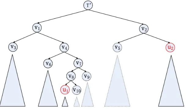
To better illustrate how the algorithm works, let us consider an example in Figure 2. In the
figure, U1 and U2 correspond to the tree nodes that incorporate the smallest and largest block
indices falling in the commit range (i.e., s and e), respectively, and T0 is their lowest common
ancestor (as defined on lines 3–4 of Algorithm 8). The nodes and their subtrees shown using dotted lines corresponds to the nodes whose entire subtrees are to be removed. To remove all nodes in
the subtree of T0 with block indices larger than adjusted s (located in the left child’s subtree), we
traverse the path from u1 toT0. Every timeu1 is the left child of its parent, we removeU1’s right
sibling and its subtree, remove u1’s parent node, and make u1 take the place of its parent (lines
Algorithm 7 UTRetrieve(u,s,e)
1: C=∅
2: if (u= NULL)then
3: w=UTCreateNode(s,e,0,0,0)
4: C=C∪ {w}
5: else
6: if (u.L≤s−u.Rand e−u.R≤u.U)then
7: if (u.Op6=−1)then
8: C=C∪ {u}
9: else
10: C=C∪ {UTRetrieve(u.Pr,s+u.U−u.L+ 1,e+u.U−u.L+ 1)}
11: end if
12: else if (e−u.R<u.L)then
13: C=C∪ {UTRetrieve(u.Pl,s,e)}
14: else if (s−u.R>u.U)then
15: C=C∪ {UTRetrieve(u.Pr,s−u.R−u.Op(u.U−u.L+ 1),e−u.R−u.Op(u.U−u.L+ 1))}
16: else if (s−u.R<u.Land u.L≤e−u.R≤u.U)then
17: C=C∪ {UTRetrieve(u.Pl,s,u.L+u.R−1)}
18: C=C∪ {UTRetrieve(u,u.L+u.R,e)}
19: else if (u.L≤s−u.R≤u.Uand e−u.R>u.U)then
20: C=C∪ {UTRetrieve(u.Pr,u.U+ 1−u.Op(u.U−u.L+ 1),e−u.R−u.Op(u.U−u.L+ 1))}
21: C=C∪ {UTRetrieve(u,s,u.U+u.R)}
22: else if (s−u.R<u.Land e−u.R>u.U)then
23: C=C∪ {UTRetrieve(u.Pl,s,u.L+u.R−1)}
24: C=C∪ {UTRetrieve(u.Pr,u.U+ 1−u.Op(u.U−u.L+ 1),e−u.R−u.Op(u.U−u.L+ 1))}
25: C=C∪ {UTRetrieve(u,u.L+u.R,u.U+u.R)}
26: end if
27: end if
28: return C
together with their subtrees, nodesv8 andv7 are also removed, andu1 takes te place ofv7. At this
point u1 becomes the right child of its parent, and we balance the subtree rooted at u1’s parent
and make u1 point to its parent node (lines 30–32 of the algorithm). This means that rebalancing
is executed (if necessary) afteru1 takes place of v7, v4, and v1. In the general case, the process of
removing nodes and subtrees and rebalancing repeats untilu1 becomes the direct child of T0.
The same process applies to the right child’s tree of T0 that containu2 with the difference that
node removal is performed when u2 is the right child of its parent and rebalancing is performed
when u2 is the left child of its parent (lines 34–40 of the algorithm). For the example in Figure 2,
we obtain that nodev5 is removed together with its subtree, node v2 is removed, and u2 takes the
place ofv2.
The last step that remains is to rebalance the subtree rooted at T0 and the subtrees of all other
nodes on the path from T0 to the root. This is accomplished on lines 42–45 of the algorithm by
making T0 point to its parent after each rebalancing procedure. We obtain a balanced tree Twith
all nodes in the range [s,e] removed and insert one single node corresponding to this range that
indicates that the commit number CIDof all blocks in the range [s,e] has been increased.
6
Analysis of the Scheme
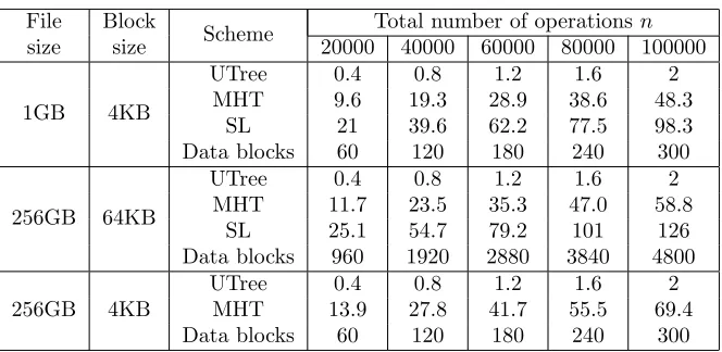
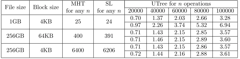
Complexity analysis. In what follows, we analyze the complexity of main update tree algorithms
Algorithm 8 UTCommit(T,s,e)
1: CID=CID+ 1
2: S=UTRetrieve(T,s,e)
3: set u1 and u2 to be the nodes inS, that are part of the tree, and has the smallest and largest indices respectively
4: set T0 to be the lowest common ancestor ofu1 andu2 in S
5: set s0 to besadjusted through traversal
6: set e0 to beeadjusted through traversal
7: if s06=u1.L then
8: UTSetNode(u1,u1.L,s−1,u1.V,u1.ID,u1.Op)
9: w1=UTCreateNode(s,u1.U,u1.V,u1.ID,u1.Op)
10: UTInsertNode(u1.Pr,w1,left)
11: end if
12: if e06=u2.U then
13: UTSetNode(u2,e0+ 1,u2.U,u2.V,u2.ID,u2.Op)
14: w2=UTCreateNode(u2.L,e0,u2.V,u2.ID,u2.Op)
15: UTInsertNode(u2.Pl,w2,right)
16: end if
17: if u16=u2 then
18: if (u1.Pr= NULL)6 and (u1is notu2’s ancestor)then
19: UTFree(u1.Pr)
20: u1=UTBalance(u1)
21: end if
22: if (u2.Pl= NULL)6 and (u2 is notu1’s ancestor)then
23: UTFree(u2.Pl)
24: u2=UTBalance(u2)
25: end if
26: while(u1.Pp6=T0)and (u16=T0)do
27: if u1=u1.Pp.Pl then
28: UTFree(u1.Pp.Pr)
29: set u1to be a direct child ofu1.Pp.Pp
30: else if u1=u1.Pp.Prthen
31: u1=UTBalance(u1.Pp)
32: end if
33: end while
34: while(u2.Pp6=T0)and (u26=T0)do
35: if u2=u2.Pp.Pr then
36: UTFree(u2.Pp.Pl)
37: set u2to be a direct child ofu2.Pp.Pp
38: else if u2=u2.Pp.Plthen
39: u2=UTBalance(u2.Pp)
40: end if
41: end while
42: while(T06= NULL)do
43: T0 =UTBalance(T0)
44: T0 =T0.Pp
45: end while
46: else
47: removeu1from the tree
48: end if
49: UTModify(T,s,e)
Figure 2: Illustration of the commit algorithm.
operations are performed during the process of traversing the tree. Therefore, its time complexity
isO(logn), where nis the current number of nodes in the tree. BothUTModify andUTDeletecan
add between 0 and O(min(n,e−s)) nodes to the tree, but as our experiments suggest, a constant
number of nodes is added on average. Their time complexity is O(logn+ min(n,e−s)), and both
the size of the range e−s+ 1 and the number of nodes in the tree form the upper bound on the
number of returned nodes. UTRetrievedoes not add nodes to the tree and its complexity is similarly
O(logn+ min(n,e−s)). Lastly, UTCommit removes between 0 and O(min(n,e−s)) nodes from
the tree and its time complexity is alsoO(logn+ min(n,e−s)).
Because the complexity of UTCommit is less trivial to compute, we analyze it in more detail.
Note that UTCommit calls the tree rebalancing function UTBalance, the worst case complexity of
which isO(logn), at mostO(logn) number of times. However, due to the careful construction of the
tree and the commit function, the total number of operations that rearrange the tree perUTCommit
is onlyO(logn) (plus, node deallocation time which gives the totalO(logn+ min(n,e−s)) time).
Theorem 1 The time complexity of UTCommitis O(logn+ min(n,e−s))).
Proof In what follows, we assume that a tree is balanced if for each node in the tree the heights of subtrees rooted at the node’s children differ by at most 1. In other words, rebalancing is triggered
when the height difference is 2 or more. More generally, any constant c ≥ 2 can be used as the
criterion for rebalancing, and the claimed complexity will still hold.
It is clear that memory deallocation time associated with the nodes whose subtrees are being
removed from the tree, i.e., the aggregate complexity of all UTFree calls, is O(min(n,e−s)) and
we therefore concentrate on showing that the rebalancing itself takesO(logn) time.
Recall that the complexity ofUTBalance, when executed on a tree both child subtrees of which
are balanced is linear in the height difference of the child subtrees. Also recall that duringUTCommit
we first locate the nodes that contain the smallest and largest block indices falling within the commit
range (u1 and u2, respectively), and then call either UTBalance or UTFree during the process of
moving up toward their lowest common ancestor T0. As was shown earlier, when u1 is the left
child of its parent onlyUTFree is called and no rebalancing takes place, but this can increment the
difference in the height of u1’s subtree and that of its new sibling by 1 or 2 (the latter happens
only ifu1’s original sibling had a subtree with the larger height and the new sibling has the subtree
of larger height than u1’s original parent node). After performing this step multiple times (where
number of timesu1 is moved up the tree. Referring back to the example in Figure 2, whenu1 takes
the place of v7, the difference between the heights of trees rooted at sibling nodes v6 and u1 can be
larger by at most 2·2 than the original difference between the heights of the trees rooted atv6 and
v7.
When u1 is the right child of its parent, we call the rebalancing procedure on u1’s parent.
In this case, the maximum height difference of its two subtrees is equal to twice the number of UTFree operations issued since the occurrence of the most recent UTBalance plus 1. Going back
to the example in Figure 2, when UTBalance is called on v4 (i.e., after replacing v7 withu1), the
maximum height difference between the subtrees rooted at v6 and u1 is 5. The height difference
then defines the runtime of the balancing procedure, which is linear in that difference. For the
consecutive operations in the figure whileu1 remains the right child of it parent and moves up the
tree, the difference between the heights of children subtrees of the nodes being rebalanced can be
at most 2 and thus balancing takes constant time. The same analysis applies to node u2 with the
procedures invoked when u2 is the left or right child of its parents reversed from those foru1.
We obtain that the aggregate time for rebalancing the tree rooted at T0 is linear in the number
of calls toUTFreeandUTBalanceor the height of the treeTand is thereforeO(logn). The commit
function also balances the overall treeTasT0moves up the tree one node at a time. The complexity
of this process can be shown similar to the complexity of balancing the subtrees while u1 remains
to be the right child of its parents and moves up the tree (i.e., the initial rebalancing cost can be
at most linear in the distance fromT0 to the leaf level of the tree, but the cost of each consecutive
rebalancing operation is constant). We obtain that the overall rebalancing cost of UTCommit is
O(logn) and its overall cost is O(logn+ min(n,e−s)))
Next, we analyze the complexity of the protocols themselves. It is easy to see thatInithas time and
communication complexity of N, i.e., the number of transmitted blocks. Updatefor any operation
has time complexity of O(logn+num) and communication complexity of O(num). Retrieve has
the same complexities as Update, unless it is used for integrity verification only rather than block
retrieval. In the latter case, its computation and communication complexities become O(logn+
min(num, c)) and O(min(num, c)), respectively, where constant c bounds the number of hmi, tii
pairs transmitted for the purpose of probabilistic verification. Lastly, the complexities of Commit
areO(logn+num) andO(num), because the client needs to communicatenumMACs to the server.
Security analysis. Security of our scheme can be shown according to the definition of DPDP in Section 3.
Theorem 2 The proposed update tree scheme is a secure DPDP scheme assuming the security of MAC construction.
Proof sketch Suppose that the adversaryAwins the data possession game. Then the challenger
can either extract the challenged data blocks (i.e., ifAhas not tampered with them) or break the
security of the MAC scheme (i.e., ifA tampered with the data). In particular, in the former case,
the challenger can extract the genuine data blocks from A’s response. In the latter case, if the
adversary tampers with a data block (by possibly substituting it with a previously stored data for the same or a different block), it will have to forge a MAC for it, which the challenger can use to win the MAC forgery game. This is because our solution is designed to ensure that any two MACs communicated by the client to the server are computed on unique parameters. That is, two
different versions of the same data block i will have either their version, CID, or operation type
differ, while two different blocks that at different points in time assume the same index i (e.g., a
deleted block and a block inserted in its place) can be distinguished by the value of their ID (i.e.,
The probability that a cheating server is caught on a RetrieveorChallenge request of sizenum< c
is always 1, and the probability that a cheating server is caught on a request of size num ≥ c is
1−((num−t)/num)c, wheretis the number of tampered blocks among the challenged blocks.
7
Extending the Basic Scheme
7.1 Enabling multi-user support
In this section, we extend our scheme with support for multiple users who would like to jointly access outsourced data. Two additional considerations now come in play and affect how a DPDP scheme
operates: access controlandconflict resolution. That is, in a generic multi-user environment, access
to an object is permitted according to a predefined access control policy, and simultaneous updates by multiple users of the same shared content require additional provisions. In what follows, we
base our description on user trust relationships and distinguish betweendistributed and centralized
settings.
Distributed setting. In this setting, the users trust each other; they locally maintain update trees and notify each other about updates on the shared data. First, the users identify the set of unique permissions that exist within the entire storage. Each unique set of access rights can be specified as a group of users who are granted access to the data objects with the respective permissions. In this collaborative environment, user groups can also be formed based on user preferences. The outsourced data is then divided based on the set of permission groups, each portion is assigned a
unique key1, and each user maintains a key and separate update tree for the portion of the storage
associated with each group to which the user belongs. By maintaining trees only for the data blocks to which the user has access, the user’s storage is reduced to the necessary minimum. Also, all users within the same permission group will announce their updates and synchronize them with other members of the group, which makes an exclusive tree for each group attractive, as all users will maintain identical copies of the tree and locally balance them in exactly the same way.
Each time user U performs an update on shared objects, the user notifies the remaining
mem-bers of the group about the update, which allows them to consistently modify their copies of the respective update tree. To enable users to maintain consistent views in presence of conflicting updates, we propose for the users to maintain loosely synchronized clocks and in each time slot first announce their intended requests to the group, resolve any conflicts that arise, and only then
submit the requests themselves. In detail, whenU would like to submit a request to the server, it
announces its intent (the operation type, index range, and the time slot) to the members of the permission group, and after the end of the time slot determines if any conflicts arise. We categorize
all conflicts intoautomatically resolvable (performed locally by each user) andmanually resolvable
(require user interaction), which are detailed below. After conflict resolution,U submits her request
to the server together with the proper ordering of the request and other simultaneous requests with which it conflicts (which, for instance, could be indexed by user id and sequence number). This will ensure that, even if the server receives users’ requests out of order, their proper order will be enforced when it has impact on consistency and data verifiability. In presence of many simultane-ous requests, the users determine if they are conflicting by considering each pair of them. In what follows, we exemplify our strategy for two conflicting requests, but it can be easily extended to resolve conflicts between a larger number of requests:
1One key is required for scheme operation (i.e., MAC computation), but if data confidentiality is also desired, the