EXPERIMENTAL MEASUREMENT OF DYNAMIC SIFs THROUGH
IMPACT BENDING TESTS
V.M.Chavan1, S.K.Maiti2, B.K.Dutta3
1
Refuelling Technology Division, Bhabha Atomic Research Centre, Trombay, Mumbai, INDIA-400085
2
Mechanical Engineering Department, IIT Bombay, Powai, Mumbai, INDIA-400076
3
Reactor Safety Division, Bhabha Atomic Research Centre, Trombay, Mumbai, INDIA-400085 E-mail of corresponding author: [email protected]
ABSTRACT
The paper shows that dynamic fracture toughness can be determined through collection of striker force and/or support reaction history during experiment and a Timoshenko beam model of precracked one- and three-point bend specimens. The predictions based on this approach have been compared with the results based on experimental strain gage records and the three-parameter approach of Dally and Sanford. The agreement is good. The beam model and experimental data are presented.
INTRODUCTION
To facilitate design of machines and structural components subjected to high strain rates collection of fracture toughness data through dynamic testing have become very important. Dynamic fracture toughness evaluation over a wide range of loading rates is often done through impact tests of edge-cracked bend specimens using modified Kolsky bars (split-Hopkinson bars), drop weight towers, modified Charpy testers, and electromagnetic loading schemes. To obtain valid test data it is necessary to maintain constant loading rate through the test duration till crack initiation. If size of the plastic zone near the crack tip is very small compared to the specimen dimensions, the stress field near a crack can be obtained through linear-elastic fracture mechanics. Under this condition the state of stress near crack tip can be described in terms of the stress intensity factor (SIF), . The SIF is essentially a measure of the driving force at the crack tip. At the point of fracture it reaches a critical level, which is a measure of resistance of the material to crack propagation. It is referred to as the fracture toughness ( ) and is a material property.
Direct measurement of the SIFs has been possible through the method of caustics, which is based on the recording of crack-tip out-of-plane deformations [1]. Alternatively, the SIF has been obtained by measuring strain history with strain gauges placed near the crack tip [2,3]. For routine testing, strain gauging may be tedious and costly. Any analytical or numerical method, that can help to estimate the SIF history from measurement of striker force or impact velocity, will be very useful.
The temporal motion of an impact loaded TPB specimen can be obtained in a variety of ways. Inertia loading due to impact makes the situation very distinctive. Some researchers [4,5] have considered a simplified spring-mass model for the pre-cracked specimen. Others have modeled [6,7] the crackby representing the local effects through change of moment of inertia. Modeling of a crack using a massless rotational spring positioned at the crack location has been widely employed in crack detection based on vibration [8-12] in beam like components. In the present work a model based on this approach is presented for impact analysis of the TPB specimen. The modeling can help to evaluate the history of variation of the SIF with time. The fundamental assumption here is that the spatial variation of field variables over the entire specimen including the boundaries is related to the boundary loads irrespective of static or dynamic loading.
Some researchers attempted to use far field boundary measurements and quasi-static relationships to obtain the local crack tip SIF. Recently, Foster et al. [13] have adapted a modified Kolsky pressure bar to determine dynamic crack initiation toughness of high-strength steel alloy (4340 steel) at loading rate in the range of 2 to 6 x 10⁶ √ . A four-point bending configuration and a pulse shaper is used to achieve constant loading rate and to ensure dynamic equilibrium across the specimen. They have found monotonically increasing rate dependence of crack initiation toughness for 4340 steel.
Among the early investigators Bohme and Kalthoff [1] used a three-point bend configuration with a drop weight tower to apply dynamic load. They recorded the history of loading at the striker contact point and the two supports. They were able to record the ‘loss of contact’ between specimen and support during the test. The SIF was determined through local crack tip field measurements using the method of caustics.
invalid, they [4-7] use the far-field loading history and time-to-fracture from experiment, combined with either analytical of numerical model to determine the dynamic crack initiation toughness.
This paper presents a method to determine variation of SIF from the history of specimen displacement obtained through an analytical model of the specimen [14] and experimental load-time data. The experiments have been done with edge crack beam specimens at loading rates 1x10⁶ √ . The tests were carried out both at sub-zero and room temperatures. The SIFs predicted through the model have been compared with the results based on the experimental measurements of strains near the crack tip using strain gauges.
ANALYTICAL MODELING
The usual impact test specimens can be represented as a Timoshenko beam with a crack. In the case of pure bending of such a beam it can be assumed that the crack gives rise to an extra angular rotation at its location (Fig. 1), which is equal to ⁄ , where is the local bending moment and is the stiffness of the rotational spring (Fig. 1b). is related to the specimen cross-sectional dimensions and crack length [14].
(
)
(
)
4 2 072
K aa f a W da
E BW
;
θ
=
π
∫( )
1 2 2
3 2 1 99 1 2 15 3 93 2 7 3
2
1 2 1
a a a a a
. . . .
W W W W W
a f W a a W W ⎡ ⎛ ⎞⎤ ⎛ ⎞ ⎢ −⎛ ⎞⎛ − ⎞⎜ − ⎛ ⎞+ ⎛ ⎞ ⎟⎥ ⎜ ⎟ ⎢ ⎜ ⎟⎜ ⎟⎜ ⎜ ⎟ ⎜ ⎟ ⎟⎥ ⎝ ⎠ ⎣ ⎝ ⎠⎝ ⎠⎝ ⎝ ⎠ ⎝ ⎠ ⎠⎦ = ⎛ + ⎞⎛ − ⎞ ⎜ ⎟⎜ ⎟ ⎝ ⎠⎝ ⎠ (1)
wheref (a W)is given by ASTM E399, and
a
is size of the crack,B
is thickness, andW
is width.While analyzing the results obtained through impact test of TPB specimens, it is usually presumed that the specimen is in contact with the supports continuously. In reality, this does not always happen. In many situations, at the initial stages, the beam is in a free-free state and loading occurs entirely
(a) (b) Kθ= Rotational spring stiffness
Fig. 1: (a) Precracked three-point bend specimen under applied forceF t( )and support reactionR t( )and (b) superposition scheme for analysis of motion of beam by invoking rotational spring at crack location.
due to the specimen inertia. The loss of contact from the supports in the three-point bend test was first reported by Bohme and Kalthoff [1]. They further reported that the specimen contacts the supports only after a finite period of time. In order to obtain the history of motion of a specimen of this type, a new strategy can be considered. The beam can be considered to be always free-free and it is subjected to two sets of time-dependent loads, one due to force acting at the striker-beam contact location and others at the beam-support contact points (Figs. 1a and b). The motion of the beam can be obtained by superposing motions in the two cases. This helps even to take care of situations, where the two sets of forces may or may not start at the same time or even when there is a loss of contact between specimen and the striker or anvils or both together. Striker force and support reaction can be represented through Fourier series.
0
1 1
( )
sin(
)
cos(
)
n n
i i i i
i i
F t
P
P
ω
t
Q
ω
t
= =
=
+
∑
+
∑
and 01 1
( )
sin(
)
cos(
)
n n
i i i i
i i
R t
R
R
ω
t
V
ω
t
= =
=
+
∑
+
∑
(2)where
ω
i is the frequency content of entire loading system including striker, specimen and anvils. The SIFs can be calculated separately for each harmonic force through the convolution integral and then combined to obtain the required SIF history as follows.0 0
( )
( ) sin
(
)
( ) sin
(
)
t t
S S
I F s s R s s
where
ω
sis the fundamental frequency of the free-free beam.K
FS andK
RS are the SIFs for the specimen subjected to unit body force loading when the transverse displacements are fixed at striker-beam and beam-support contact points respectively. These functions are determined using 2D FE model of the specimen and static analysis. The unsupported (or free-free) beam fundamental frequencyω
s is obtained through analytical modeling. The assumption of linearity makes it possible to use modal superposition as a method to obtain the approximate solution against any external excitation.
EXPERIMENTAL METHOD
Specimen Details
The three-point bend specimens from SA 516 Gr. 70 steel plate were prepared in accordance with the guidelines provided by ASTM E399 relating to dimensions, fabrication and precracking. The machined specimen dimensions are: L = 100mm, W = 20mm, and thickness B = 10mm. The machined notch was made by ED wire cutting machining through 8.5mm. The fatigue precracking was carried out through a resonant fatigue tester operating at 60-70 cycles per second. Each specimen required about 5 x 10⁵ cycles to produce 1.5mm extension so that the total crack size is 10mm or
a W
/
=
0.5
. Each sample was polished to a mirror finish at the surface ahead of the notch to allow easy visibility and monitoring of growth of crack during fatigue precracking. The crack size was measured using an optical microscope after the completion of fracture test.The steel plate from which specimens were made had dimensions 500mm x 110 mm x 85mm
approximately. The specimens were machined in the L-S orientation, i.e. the length of the specimen is along the longitudinal direction of the plate; the notch and crack plane was oriented in the thickness direction and the width of the specimen was oriented in the transverse direction. Chemical analysis of the steel plate shows the following composition.
Table 1: Chemical composition of (in % weight) SA516 (Gr.70) steel plate. C Mn Si P S Ni Cr Cu 0.24 1.14 0.2 0.016 0.022 47(ppm) 30(ppm) 180(ppm)
Three strain gauges (350 Ω, Make: TML, Japan), were fixed on the surface of each specimen. They were oriented normally to the crack plane and located at a distance of 5mm from the crack tip (Fig. 4). The size of backing foil of the strain gauge is 1mm x 1mm. One more strain gauge is mounted immediately ahead of crack tip to monitor the instance of crack initiation.
Test Setup
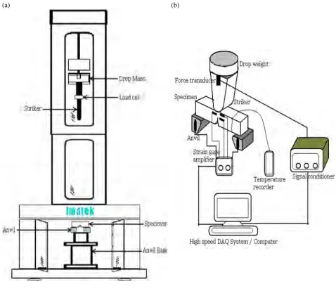
All tests were done using a drop weight testing machine (Make : Imatek, UK). The machine (Fig. 2a) allows testing under different conditions. The drop mass can be changed. The impact velocity can be varied by automatic adjustment of the drop height. The striker is instrumented with in-built pizo-electric load cell of capacity ±50 kN. A signal conditioner along with data acquisition system capable of sampling speed up to 10 million samples per second was a part of the recording system. The strains are recorded at the four locations on the specimen surface at a sampling rate of 200 kHz.
A set of anvils were fabricated to facilitate measurement of variation of support reactions with time. The anvils (Fig. 3b) were instrumented with strain gauges (Fig. 3a). The two anvils were calibrated under static loading up to 20 kN. The same calibration data was employed to obtain the support reactions during the tests. The complete test setup is shown schematically in Fig. 2b.
Calculation of SIFs
The time variation of SIF was obtained through two separate methods. In the first method the SIF was calculated using the measured strain data on the specimen surface. In other method the SIF was calculated through the measured time-varying striker force and anvil reactions and the beam model.
The strains measured through the gauges mounted on surface of the specimen were employed to obtain the SIFs through three-parameter crack-tip field solution due to Dally and Sanford [3].
{
}
{
}
0
0 1
1 3 2
cos (1 ) (1 ) sin sin 2 cos (1 ) (1 ) sin
2 2 2 2 2
( )
A B A rE r
t
θ υ υ θ θ υ θ υ υ θε
= ⎢
⎡
− + + − + − − +⎤
⎥
⎣
⎦
(4)where
K t
I( )
=
A02
π
(Fig. 4a). A0, B0and A1are the multipliers of the first three-terms of the series.(a) (b)
(a) (b)
Fig. 3: (a) Specimen mounted on instrumented anvils and (b) two anvils.
(a) (b)
Fig. 4: (a) Co-ordinate system for strain measurement, (b) Gauge locations on specimen.
(a) (b)
(a) (b)
(c) (d)
(e)
(f)
RESULTS AND DISCUSSION
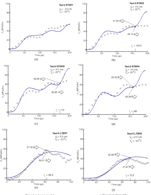
Four tests were carried out at room temperature and two at – 50 ºC (Fig 5). Comparison of the SIFs based on the beam model and the strain measurements is presented in Fig. 6. There is good correlation between analytical and experimental SIF variation till crack initiation, which occurs between 150 µs to 170 µs for specimens 2, 3 and 4 (Figs.6b, c and d) and 60µs to 80µs for specimens 5 and 6 (Figs. 6e and f). Specimen 1 did not show any crack initiation (Fig. 6a).
The SIF histories obtained by the two methods compare well. There is difference in the variation of force with time in the two cases. As seen from the SIF calculated using the strain data, the fracture load drops substantially due to crack extension. The beam model does not account for crack extension; therefore there is oscillation in SIF history even after the instance of crack initiation .
CONCLUSION
The proposed method of analysis to determine dynamic response of a symmetric free-free Timoshenko (or short) beam is quite effective to evaluate the variation of SIF with time using the static correlation of displacement with SIF. The SIF history based only on the fundamental mode is close to the experimental observations at moderate impact velocities. It is easier to evaluate the SIFs through present analytical model using and as input from experiments than through the measurements of strains. The method can be exploited for measurement of crack initiation fracture toughness under dynamic loads, making appropriate arrangement for detection of the onset of crack extension and striker and/or anvil load histories.
REFERENCES
[1] Bohme,W., Kalthoff, J.F., “The behavior of notched bend specimens in impact testing”, Int. J Fract. Vol. 20, 1982, pp. R139-143.
[2] MacGillivray,H.J., Cannon D.F., “The development of standard methods for determining the dynamic fracture toughness of metallic materials”. In: Rapid load fracture testing. ASTM STP 1130, R Chona and WR Corwin, Eds., American Society for Testing and Materials (ASTM), 1992, Philadelphia, pp. 161-179. [3] Dally, J.W., Sanford, R.J., "Strain Gage Methods for Measuring the Opening Mode Stress Intensity Factor,
KI," Expt Mech., Vol. 27(4), 1987, pp. 381-387.
[4] Lorriot T. et al., “Dynamic analysis of instrumented Charpy impact tests using specimen deflection measurement and mass-spring models”, Int. J Fract. Vol. 91, 1998, pp. 299-309.
[5] Williams, J.G., “The analysis of dynamic fracture using lumped mass-spring models”, Int. J Fract.Vol. 33, 1987, pp. 47-59.
[6] Kishimoto, K., Aoki, S., Sakata, M., “Simple formula for dynamic stress intensity factor of pre-cracked Charpy specimen”, EFM Vol. 13(3), 1980, pp. 501-508.
[7] Marur, P.R., Nair, P.S., Simha, K.R.Y., “Two degrees of freedom modeling of pre-cracked beams under impact”, EFM Vol. 53 (3), 1996, pp. 481-491.
[8] Papadopoulos, C.A., Dimarogonas, A.D., “Coupled longitudinal and bending vibrations of a rotating shaft with an open crack”, JSV Vol. 117, 1987, pp. 81-93.
[9] Ostachowicz, W.M., Krawczuk, M., “Analysis of the effect of cracks on the natural frequencies of a cantilever beam”, JSV Vo. 150(2), 1991, pp. 191-201.
[10] Doebling, S.W., Farrar, C.R., Prime, M.B., “A summary review of vibration based damage identification method”, Shock and Vibration Digest Vol. 30, 1998, pp. 91-105.
[11] Carneiro, S.H.S., Inman, D.J., “Continuous model for transverse vibration of cracked Timoshenko beams”,
Trans. ASME, J Vibration and Acoustics Vol. 124, 2002, pp. 310-320.
[12] Lele, S.P., Maiti, S.K., “Modeling of transverse vibration of short beams for crack detection and measurement of crack extension”, JSV Vol. 257(3), 2002, pp. 559-583.
[13] Foster, J.T., Chen, W., Luk, V.K., “Dynamic crack initiation toughness of 4340 steel at constant loading rates”, EFM Vol.78, 2011, pp.1264-1276.