CHANDRA, DEEPAK. Developing a Simulation Framework for Vulkan. (Under the direction of Dr. Huiyang Zhou).
Vulkan is a modern, low-level graphics and compute API by Khronos group that provides a much better abstraction of modern graphics cards. The explicit nature of the API requires the developer to be responsible for managing hardware resources and results in precise over the hardware. In this work, we develop a framework to simulate Vulkan based applications. Our framework leverages an existing GPU simulator – GPGPU-Sim – to functionally simulate programmable shader code. The framework consists of a Vulkan driver that intercepts Vulkan calls from the application and interacts with GPGPU-Sim to initialize and execute the application. The framework also implements certain fixed functional units in software which are an essential part of the graphics pipeline. We demonstrate the
by Deepak Chandra
A thesis submitted to the Graduate Faculty of North Carolina State University
in partial fulfillment of the requirements for the degree of
Master of Science
Computer Engineering
Raleigh, North Carolina 2018
APPROVED BY:
_______________________________ _______________________________ Dr. Huiyang Zhou Dr. Michela Becchi
Committee Chair
ii BIOGRAPHY
iii ACKNOWLEDGMENTS
I would first like to thank my research advisor, Dr. Zhou, without whose guidance none of this would have been possible. He has always been a pillar of support and a guiding light throughout my master’s thesis work. The door to his office was always open whenever I ran into a spot or had queries about my research or writing for which I’m very grateful.
Additionally, I would like to thank Dr. Becchi and Dr. Tuck for agreeing to be a part of my defense committee and review this thesis. The courses I took under them have helped give me a strong foundation in computer architecture and allowed me to be successful in my work.
I would also like to thank all my colleagues that worked on this project – Deepti, Sakshi, Snehal, and Sweekruth. This project would not have been successful without their contributions.
iv TABLE OF CONTENTS
LIST OF FIGURES ...v
Chapter 1: Introduction ...1
1.1 Introduction ...1
1.2 Contribution ...1
1.3 Thesis Organization ...2
Chapter 2: Background and Related Work ...3
2.1 Vulkan® ...3
2.2 GPGPU-Sim ...3
2.3 Related Work ...6
Chapter 3: Vulkan Compute...7
3.1 Introduction ...7
3.2 Vulkan Compute Pipeline ...7
3.3 Interfacing with GPGPU-Sim ...8
3.4 Detailed walkthrough of the Compute Pipeline and Application ...9
3.5 SPIR-V to PTX Compiler ...13
3.6 Individual Contributions ...14
Chapter 4: Vulkan Graphics...16
4.1 Introduction ...16
4.2 Graphics Pipeline ...17
4.3 Basic Triangle program...20
4.4 Interfacing with GPGPU-Sim ...25
4.5 Results ...27
Chapter 5: Conclusion ...29
REFERENCES ...31
Appendix A: Shader Compiler...33
Appendix B: Compute Shader ...35
Appendix C: Vertex Shader ...37
v LIST OF FIGURES
Figure 2.1 Logos of Vulkan and Khronos Group ...3
Figure 2.2 GPGPU-Sim Compile Flow ...4
Figure 2.3 GPGPU-Sim functional simulation objects ...5
Figure 3.1 Typical Compute Application ...8
Figure 3.2 Vulkan compute simulation framework ...9
Figure 3.3 Creating device and queue ...9
Figure 3.4 Allocating memories and buffers ...10
Figure 3.5 Setting up pipeline ...11
Figure 3.6 Executing workload ...12
Figure 4.1 Display path ...16
Figure 4.2 Basic graphics pipeline ...18
Figure 4.3 Normalized or homogenous coordinates ...19
Figure 4.4 Expected output of triangle program ...21
Figure 4.5 Graphics simulation infrastructure ...25
Figure 4.6 Vertex shader output ...27
1 CHAPTER 1: INTRODUCTION
1.1 Introduction
Any modern application that interacts with humans has to render graphics. For some applications these maybe simple, say a webpage. Such graphics maybe rendered completely in software running on CPU. On the other hand, applications like games create their own immersive three dimensional world and require intensive rendering to create the
photorealistic graphics. These definitely require dedicated accelerators called graphics processing units or GPUs.
Graphics libraries are software that assist applications in rendering by exposing standardized operations via an Application Programming Interface or API. Such libraries are provided by device vendors as part of their device drivers. The exposed API is standardized but there a number of them. Some are proprietary and work only with specific hardware for example Direct3D by Microsoft works only for Windows and Xbox systems, Metal by Apple works only on Apple hardware, and CUDA by Nvidia specifically for compute. There are others that are open source such as OpenGL for graphics and OpenCL for compute.
Vulkan is a modern API that supports both graphics and compute applications. It is platform agnostic which allows the application to be developed independent of target platform. It is also low level and explicit in nature which allows the developer to have full and precise control over the hardware which results in consistency across different hardware. 1.2 Contribution
2 CUDA/OpenCL workloads. On top of this, a layer of Vulkan driver is built that interacts with the application and simulates the workload using GPGPU-Sim.
1.3 Thesis Organization
3 CHAPTER 2: BACKGROUND AND RELATED WORK
2.1 Vulkan®
Vulkan® [1] is a modern, cross-platform, low level, and open three dimensional graphics and compute API which is being developed by the Khronos™ Group [2]. It gives direct access of the GPU to developers. It has a simple and thin driver stack making it lower latency and overhead API compared to traditional OpenGL or Direct3D. Vulkan also has efficient multi-threading capabilities ensuring that multi-core CPUs can feed the graphics pipeline to full extent.
Being a cross platform API, Vulkan allows developers to create applications that can run across a variety of hardware ranging from personal computers, mobile devices and embedded systems. Being an open standard, it is available royalty free for any platform to adopt.
All these benefits come at a price – the API is significantly verbose. Every little detail related to the API needs to be setup and managed by the application explicitly.
Figure 2.1 Logos of Vulkan and Khronos Group 2.2 GPGPU-Sim
GPGPU-Sim 3.x [3] is a Performance Simulator for Many Core Accelerator Research. It is a cycle-level simulator modeling contemporary graphics processing units (GPUs) for running GPU computing workloads written in CUDA or OpenCL.
GPGPU-Sim simulates –
4 Timing model for GPU compute
Power model for GPU compute
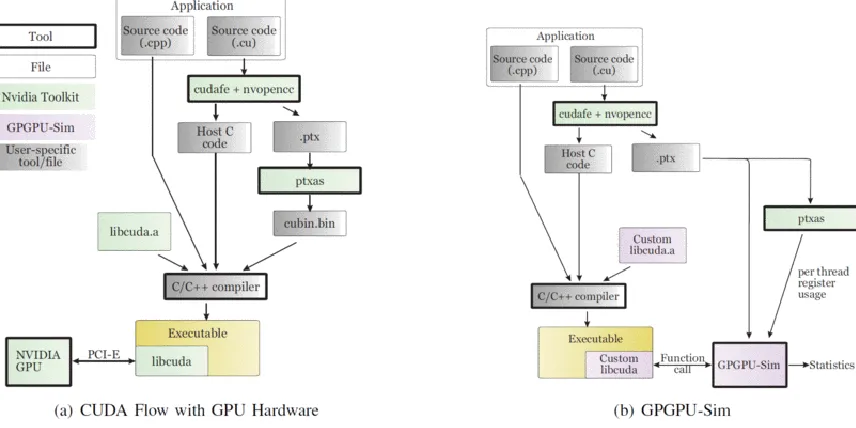
GPGPU-Sim is compiled into stub libraries that dynamically link at runtime to the CUDA/OpenCL application. Those libraries intercept the call intended to be executed by the CUDA runtime environment and instead initialize the simulator and run the kernels on it instead of on the hardware. Figure 2.2 shows the compile flow for a CUDA application for both with and without GPGPU-Sim.
Figure 2.2 GPGPU-Sim Compile Flow
When building a CUDA application, NVIDIA's nvcc translates each kernel launch into a series of API calls to the CUDA runtime API, which prepares the GPU hardware for kernel execution. libcudart.so is the library provided by NVIDIA that implements this API. In order for GPGPU-Sim to intercept those calls and run the kernels on the simulator,
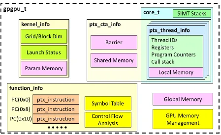
5 To support functional simulation, the simulator maintains a number of key objects internally. Figure 2.3 shows the relationship amongst them. All these objects have to be initialized and maintained properly to ensure correct functional behavior.
Figure 2.3 GPGPU-Sim functional simulation objects
The kernel_info stores the kernel launch parameters and arguments passed to the kernel function. Threads are defined by their program counters, registers and set of local memory locations. A CTA is a block of threads with access to shared memory and barrier.
6 2.3 Related Work
There has been prior work for creating simulators for graphical pipeline –
7 CHAPTER 3: VULKAN COMPUTE
3.1 Introduction
CUDA is the most widely used programming architecture for GPU compute. However it is Nvidia proprietary and runs only on Nvidia hardware. OpenCL is the open source alternative supported by all major GPU hardware vendors. With Vulkan, there is support for both graphics and compute workloads using a single API.
Vulkan being a low level API shifts the burden of proper hardware resource
management onto the developer. This makes the application code involve a lot of boilerplate code to get things up and running but gives the developer much more fine-grained control over how the resources are allocated and where are they laid out.
GPGPU-Sim already supports CUDA and OpenCL. Our starting point was to
understand how OpenCL interacts with GPGPU-Sim for initialization, memory management, kernel invocation, etc. and correlate the same for Vulkan.
We built a Vulkan frontend wrapper for GPGPU-Sim. It’s exposed as a runtime Vulkan library which the application can include as “vulkan.h”. The wrapper has definitions for the various Vulkan opaque structures and API calls. The API calls internally call function to interact with GPGPU-Sim.
3.2 Vulkan Compute Pipeline
In Vulkan, a compute pipeline consist of a single compute shader stage and the pipeline layout. The shader stage contains the compute code that is to be executed. The pipeline layout describes the complete set of resources that can be accessed by a pipeline.
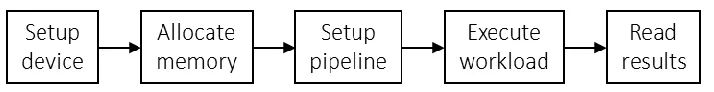
8 1. Creating device and queue
2. Allocating memories and buffers
3. Setting up the pipeline
4. Executing compute workload
5. Getting back results
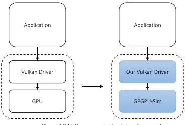
Figure 3.1 Typical Compute Application 3.3 Interfacing with GPGPU-Sim
9
Figure 3.2 Vulkan compute simulation framework 3.4 Detailed walkthrough of the Compute Pipeline and Application
In the following text, we deep dive into what each step does and how it is integrated with GPGPU-Sim.
1. Creating device and queue (Figure. 3.3) –
Figure 3.3 Creating device and queue
We start by creating an instance of Vulkan application using “vkCreateInstance”. It is during this call that we initialize the simulator creating a virtual GPU object. Next we query the hardware for a list of GPU devices and the supported queue types on the devices using “vkEnumeratePhysicalDevices” and
Application
Vulkan Driver
GPU
Application
Our Vulkan Driver
10 “vkGetPhysicalDeviceQueueFamilyProperties” functions. This virtual GPU object and its queue are exposed to the developer when it creates a Vulkan virtual device and a compute queue on it to submit compute workloads using
“vkCreateDevice” and “vkGetDeviceQueue” functions. 2. Allocating memories and buffers (Figure. 3.4) –
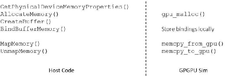
Figure 3.4 Allocating memories and buffers
In Vulkan, a buffer is a memory object that the compute workload (also known as a compute shader) interacts with or works upon. It is an abstraction of the actual memory on the device. This is analogous to a pointer and heap memory in a traditional C program. The code allocates the memory with “vkAllocateMemory” which results in GPGPU-Sim allocating the memory from the simulated device memory. The code then creates two buffer objects using “vkCreateBuffer” (one for each input matrix), and then binds the buffer to the allocated memory regions using “vkBindBufferMemory”. We create a mapping of these bindings internally as they are needed later on when we actually execute the workload.
11 “vkUnmapMemory” removes this mapping. To facilitate this, the wrapper
allocates memory on host (using malloc) and copies over the device memory data. Upon a call to remove the mapping, the wrapper copies the data back to device memory and frees the memory allocated on the heap. Due to this copying back and forth of data between host memory and device memory, it is necessary to map and un-map memories before executing device code and then again mapping it once it’s over.
3. Setting up the pipeline (Figure. 3.5) –
Figure 3.5 Setting up pipeline
Vulkan involves a few steps for setting up the stage to executing a compute shader. First we create a shader module using “vkCreateShaderModule” which contains the shader code in SPIR-V (or PTX for our case) format. Next we create a descriptor set layout using “vkCreateDescriptorSetLayout” which essentially specifies the numbers and type of memory objects that the shader code interacts with. For our vector add, we have two objects each of type buffer (matrix A and B). The code then links the shader module with the descriptor set using
12 framework to convert SPIR-V into PTX code. The shader code must be
pre-compiled onto PTX and then passed into the shader module.
4. Executing the workload (Figure. 3.6) –
Figure 3.6 Executing workload To execute the workload, we create a descriptor set, using
“vkAllocateDescriptorSets”, and update it, using “vkUpdateDescriptorSets” to contain bindings for the buffers in the correct order. The wrapper uses this to internally create a mapping for the buffers as arguments to the PTX code. The code allocates a command buffer using “vkAllocateCommandBuffers” and binds it to the pipeline with “vkCmdBindPipeline”.
The shader is dispatched using “vkCmdDispatch”. This call provides the wrapper with the number of workgroups to launch in x, y and z dimension (grid
13 To execute the workload, this command buffer is submitted to the compute queue using “vkQueueSubmit”. This is where the wrapper launches the compute kernels with the correct arguments and grid dimensions.
To wait till the entire workload has finished, a “vkQueueWaitIdle” is called on the compute queue. However since our wrapper launches the compute kernels while handling the “vkQueueSubmit”, it returns only once all the kernels have been simulated. Hence the wrapper implements “vkQueueWaitIdle” as an empty function.
5. Getting back results –
The code then maps the memory region containing output buffer using “vkMapMemory” and verifies the final data.
The sample shader code and its equivalent CUDA kernel code are available in appendix.
3.5 SPIR-V to PTX Compiler
14 To tackle such situations, another member of our group, Sweekruth, is working on developing a standalone compiler that takes in SPIR-V and generates equivalent PTX. The project is based on LunarG’s LunarGLASS which is an LLVM-based shader-compiler stack and optimizer for shaders, including front-end adapters for GLSL and SPIR-V and a back-end adapter for GLSL, called LunarGOO.
The main work done is implementing a PTX backend that converts the internal IR into PTX code. The upper layers are used as is and the control flow remains unchanged. The GLSL backend is used as a template for our own PTX backend. The front end ingests the shader code, it’s converted to the bottom IR and the backend interprets each operation in bottom IR using the metadata generated by the front end.
3.6 Individual Contributions
Acknowledging the vast scope of the project and intricate knowledge of Vulkan, OpenCL, CUDA APIs and GPGPU-Sim required, this part of the project was done as a group consisting of Deepti, Sakshi, Snehal, Sweekruth, and myself.
As mentioned before, Sweekruth’s efforts are focused towards developing a compiler for translating shader code into PTX.
16 CHAPTER 4: VULKAN GRAPHICS
4.1 Introduction
A Graphics API provides an interface for applications to interact with the underlying hardware to generate and display images on the screen (Figure. 4.1). Such applications are used extensively in the fields of computer-aided design (CAD), virtual reality, scientific visualization, information visualization, flight simulation, and video games. Different
platforms support different APIs – Direct3D (part of DirectX) by Microsoft for Windows and XBOX, Vulkan and OpenGL by Khronos Group which is platform independent, Metal by Apple for macOS, etc.
Figure 4.1 Display path
The Khronos Group states that “Vulkan is a new generation graphics and compute API that provides high-efficiency, cross-platform access to modern GPUs used in a wide variety of devices from PCs and consoles to mobile phones and embedded platforms.”[1]
Vulkan is designed as an "explicit API". The application has direct control and is responsible for managing the device resources. This adds complexity for the application
Application
Graphics API
GPU
17 programmer but makes the drivers simpler and low overhead resulting in greater efficiency and consistency across vendors.
In the following sections, we will go over the basics of a graphics pipeline, then over a basic program to draw a triangle and see how it works with our simulator.
4.2 Graphics Pipeline
The graphics pipeline is a model that describes what steps a system needs to perform to render a three dimensional model onto a two dimensional screen (the viewing surface or an output image). The three dimensional model is made up of points (or vertices) connected together to form surfaces. The most basic structure (also called a primitive) is a triangle which is made up of three vertices. The application issues a “draw” call for every primitive that forms a part of the three dimensional model. These calls are then passed to the
underlying graphics hardware.
18
Figure 4.2 Basic graphics pipeline Input assembler –
This stage collects the raw vertex data for a primitive and sends it down the pipeline. Since a vertex may be shared between multiple primitives, the draw call can refer to vertices by their index to avoid duplicating vertex data across draw calls.
Vertex shader –
This stage processes each incoming vertex and generally applies transformations to turn vertex positions from model space to screen space. It also transforms the vertex attributes, like color and texture coordinates, and passes them down the pipeline.
Vertex/Index Buffer
Input Assembler
Vertex Shader
Rasterizer
Color Blending Fragment Shader
Framebuffer
Fixed function unit
19 The final position of vertex is in clip coordinate which is a four dimensional vector that is subsequently converted into a normalized device coordinate by dividing the whole vector by its last component. These normalized device coordinates are homogeneous coordinates that map the framebuffer (output surface) to a [-1, 1] by [-1, 1] coordinate system (Figure 4.3).
Figure 4.3 Normalized or homogenous coordinates Rasterizer –
The job of this stage is to discretize the primitives into fragments. These are the pixel elements that they fill on the framebuffer. It can be configured to output fragments that fill entire polygons or just the edges (wireframe rendering). Any fragments that fall outside the screen are discarded and the attributes outputted by the vertex shader are interpolated across the fragments. Usually the fragments that are behind other primitive fragments are also discarded here because of depth testing.
20 This stage is invoked for every fragment that is visible in the screen space and determines the final color and depth values. It does this using the interpolated data from the vertex shader generated by the rasterizer.
Color blending –
After a fragment shader has returned a color, it needs to be combined with the color that is already in the framebuffer. This transformation is known as color blending and there are two ways to do it - simply overwrite each other, or add up or be mixed based upon transparency.
Input assembler, rasterizer and color blending are fixed function stages. Their functionality is predefined but can be tweaked via parameters and knobs.
Vertex and Fragment shader are programmable stages. The application developer writes code for these stages to perform desired functions. These programmable shaders is what allows this simple pipeline to be customized to do virtually anything from simple transformations to complex ray tracing to render photorealistic graphics.
4.3 Basic Triangle program
21 Figure 4.4 Expected output of triangle program
1. Instance and physical device selection
The application starts by creating an instance using “vkCreateInstance” where the application description and API version being used are specified. Next we query the system for all supported hardware devices using
“vkEnumeratePhysicalDevices” and select the desired device with the required properties.
2. Logical device and queue families
Now that we have a physical device, we need to create a logical device handle using which we’ll interact with this device. This is done using “vkCreateDevice”. Since this is a graphics applications, we need a queue with graphics support. We get a list of all supported queue families for our device with
“vkGetPhysicalDeviceQueueFamilyProperties” and select the appropriate one with “vkGetDeviceQueue”.
3. Vertex data
22 and bind it with the buffer by means of “vkBindBufferMemory”. We fill up this buffer with our vertex data. Usually, vertex can have more attributes than just position, for example, color. Each element contains all attributes for a single vertex – in this case, just position.
4. Image views and framebuffers
Framebuffers are the target output of the graphics pipeline. Vulkan uses objects of type “VkImage” as framebuffers which we create using “vkCreateImage”. This is where we specify the details of the image – height (256), width (256), format (RGBA8), etc. Next we allocate the required memory for this image with the help of “vkAllocateMemory” and then bind it with the image using
“vkBindImageMemory”.
Before a pipeline stage can use a VkImage, we have to create an image view which describes what kind of image it is and how to access it. This is done using “vkCreateImageView”. This image view is used to create a framebuffer to which the pipeline will interact. This is done later once we have created the render pass using “vkCreateFramebuffer”.
5. Render passes
Here we describe the types of images that are used during rendering operations, how they are used, and how their contents are to be treated. For our triangle drawing, we used only a single image as the color target. These are specified using attachment descriptions.
23 passes, for example a sequence of post-processing effects that are applied one after another. In our case, we have only a single subpass. All this information is brought together to create a render pass using “vkCreateRenderPass”. Now we create a framebuffer to which our render pass outputs to.
6. Graphics pipeline
The graphics pipeline is the sequence of operations that generate the final pixels from the triangles and other primitives. This is where we provide the vertex and the fragment shader and tune the parameters of the fixed functional units as per the desired functionality.
We start with populating input assembly parameters into
“VkPipelineInputAssemblyStateCreateInfo” object, rasterization parameters into “VkPipelineRasterizationStateCreateInfo” object, and color blending parameters in “VkPipelineColorBlendStateCreateInfo” object.
Next are the shaders. For vertex shader, we create a binding description for the vertex attributes (position and color). Now we load the precompiled shader code (in SPIR-V format) into two “VkPipelineShaderStageCreateInfo” objects – first one with vertex shader and second with fragment shader. The vertex shader is a simple shader that rotates the primitive 90° clockwise around the origin. This is done by replacing (x, y) with (-y, x). The fragment shader just colors every covered pixel red.
All these pipeline stage parameters are stored into a
24 7. Creating command buffers
In Vulkan, operations like draw are not executed directly using function calls. Instead, all the operations are recorded into a command buffer and then the command buffer is put onto the queue to execute. The advantage is that all the hard work of setting up drawing commands can be done in advance and split across multiple treads.
Before we allocate a command buffer, we need a command pool which manage the memory that is used to store the buffers. This is done with
“vkCreateCommandPool”. From this pool we allocate a command buffer using “vkAllocateCommandBuffers”.
We start a command buffer with a special “begin” – “vkBeginCommandBuffer”. Next we start the render pass with “vkCmdBeginRenderPass” and specify the render pass, framebuffer, render area and the clear state of the framebuffer (all pixels black). Now we bind the pipeline and vertex buffer using
“vkCmdBindPipeline” and “vkCmdBindVertexBuffers” respectively. Now all we need to do is draw the vertices. This is done with a single
“vkCmdDraw” call where we specify that we want to draw the three vertices from the vertex buffer.
Lastly, we end the render pass (“vkCmdEndRenderPass”) and finish recording the command buffer – “vkEndCommandBuffer”.
8. Execute and get back results
25 “vkQueueSubmit”. Now we wait for the device to go idle with
“vkDeviceWaitIdle”. Once done, we copy over the image surface which was attached to the framebuffer.
4.4 Interfacing with GPGPU-Sim
GPGPU-Sim is micro-architectural simulator for CUDA and OpenCL based compute workloads. It has no support for graphics workloads out of the box. To be able to simulate a graphics pipeline, we need to add support for both fixed functional units and programmable shaders.
Figure 4.5 Graphics simulation infrastructure
This support is added in our Vulkan wrapper for GPGPU-Sim. It acts like a Vulkan driver for GPGPU-Sim accepting API calls and doing the necessary work. Figure 4.5 represents our infrastructure.
Graphics Application
Our Vulkan Driver
26 Fixed functional units are implemented as software within the wrapper layer itself. They invoke GPGPU-Sim, feed the required inputs for the shader and then simulate the shader code. Since GPGPU-Sim can execute CUDA or OpenCL workloads, we can use it to execute the programmable shader code. However, Vulkan shader code is in SPIR-V byte code format. This is where our SPIR-V to PTX compiler comes into play. At the moment, the compiler framework does not support graphics shaders but this is a planned feature. To simulate, we wrote an equivalent CUDA kernels which were compiled to PTX and used.
The wrapper consumes the information provided by “VkGraphicsPipelineCreateInfo” and extracts and segregates the information for each fixed function unit separately. It uses this information to configure and accurately simulate the units.
The input assembler gathers all the vertices for a primitive along with their attributes together and launches the vertex shader for each vertex with specified attributes in parallel. The shaded vertices return their final position and color. The position is normalized and passed onto rasterizer.
27 For all the pixels outputted by the rasterizer, we need to execute the fragment shader code and then blend the resultant color value into the framebuffer. Blending for our case is does not do anything since there’s only one primitive.
Even though we have built the required infrastructure, it is still quite rudimentary and can do only basic operations right now. The fixed function stages have a lot of control knobs and parameters that fine tune the way they behave. All this extra functionality needs to be added and is a work in progress.
4.5 Results
The vertex shader takes the triangle and rotates it by 90° clockwise. It does this by replacing (x, y) by (-y, x). Figure 4.6 shows this transformation.
Figure 4.6 Vertex shader output
The resultant list of triangle vertices is fed to the rasterizer which returns a list of fragments that are covered by the triangle. For our frame buffer of 256x256, we got 33023 covered fragments. The list starts as –
28 4), (6, 5), (6, 6), (6, 7), (6, 8), (6, 9), (6, 10), (6, 11), (6, 12), (7, 0), (7, 1), (7, 2), (7, 3), (7, 4), (7, 5), (7, 6), (7, 7), (7, 8), (7, 9), (7, 10), (7, 11), (7, 12), (7, 13), (7, 14), (8, 0), (8, 1), (8, 2), (8, 3), (8, 4), (8, 5), (8, 6), (8, 7), (8, 8), (8, 9), (8, 10), (8, 11), (8, 12), (8, 13), (8, 14), (8, 15), (8, 16), (9, 0), (9, 1), (9, 2), (9, 3), (9, 4), (9, 5), (9, 6), (9, 7), (9, 8), (9, 9), (9, 10), (9, 11), (9, 12), (9, 13), (9, 14), (9, 15), (9, 16), (9, 17), (9, 18), …
For each fragment, we run the fragment shader. Our shader just returns the color as red which is (255, 0, 0) since we are using a RGB8 format which has 8bit for every color.
This color value along with position is sent to the color blender which writes the values to the surface. We extract this using memcpy() dump it into a file. We imported this data into python with the help of NumPy [5] and OpenCV (cv2) [6] libraries and plot it. Figure 4.7 shows the rendered image.
Figure 4.7 Rendered image
29 CHAPTER 5: CONCLUSION
This thesis explored developing an infrastructure to functionally simulate Vulkan based compute and graphical applications. This thesis utilizes GPGPU-Sim, a fairly accurate and capable CUDA/OpenCL simulator and builds upon it a driver layer for Vulkan API. The combined infrastructure enables us to simulate Vulkan applications.
The first part of this thesis describes the work done to enable Vulkan based compute applications to be simulated. The second part goes in depth about graphics pipeline and how applications interact with it. And finally how we plan to simulate the graphics workloads. The contributions of this thesis include –
We analyzed a typical compute program and the way it interacts with the underlying hardware. Because of similarities between OpenCL and Vulkan, we took inspiration from the way OpenCL kernels are handled in GPGPU-Sim and built a Vulkan driver. Our driver intercepts calls from the application storing all the necessary information internally and setting up the stage before eventually simulating the compute shader on GPGPU-Sim.
We deep dived into a graphics program understanding how Vulkan manages the hardware and controls state. Being an explicit API, Vulkan requires the
application to specify the pipeline and all stages with immense details. Our driver captures this information building up a pipeline as required by the application. Based on the draw calls, we then render the scene.
30 SPIR-V to PTX compiler – this is a critical piece of the big picture. All our
simulation has been done by manually generating an equivalent shader code in PTX and simulating that. SPIR-V for graphics is even more complex and might not be possible to write equivalent PTX shaders manually.
31 REFERENCES
[1] Vulkan https://www.khronos.org/vulkan/ [2] Khronos Group https://www.khronos.org/
[3] Ali Bakhoda, George L. Yuan, Wilson W. L. Fung, Henry Wong, Tor M. Aamodt, Analyzing CUDA Workloads Using a Detailed GPU Simulator, In proceedings of the IEEE International Symposium on Performance Analysis of Systems and Software (ISPASS), pp. 163-174, Boston, MA, April 26-28, 2009.
[4] Matthew Eldridge, Homan Igehy, and Pat Hanrahan. 2000. Pomegranate: a fully scalable graphics architecture. In Proceedings of the 27th annual conference on Computer graphics and interactive techniques (SIGGRAPH '00). ACM
Press/Addison-Wesley Publishing Co., New York, NY, USA, 443-454. DOI=http://dx.doi.org/10.1145/344779.344981
[5] NumPy is the fundamental package for scientific computing with Python. http://www.numpy.org/
[6] Welcome to OpenCV-Python Tutorial’s documentation!
33 APPENDIX A: SHADER COMPILER
The shader compiler is an essential component of the graphical driver and is
responsible for converting high level shader code into lower level machine specific ISA code. The LunarGLASS shader-compiler stack is published and maintained by LunarG. It is an LLVM based shader-compiler and optimizer stack with front-end support for GLSL and SPIR-V and back-end support for GLSL. The modular framework provided by LunarG as well as its use of LLVM make it ideal for developing a new shader-compiler that has an NVPTX backend.
The implementation provided by LunarG has a GLSL/SPIR-V front-end ingests GLSL shader code. It uses the shader code to generate an Internal Top-level IR which is platform independent. The Top-level IR is converted, via optimization passes, to another internal Bottom-level IR. The Bottom-level IR is also platform independent but can be tailored to a family of architectures. Finally the Bottom-IR is translated into target code using metadata associated with each instruction in Bottom-IR. Each instruction in the Bottom-level IR code is read serially and converted to the target code as the final step of the compilation.
The modular implementation of each layer of the compiler stack means implementing a functional NVPTX back-end would create the required shader compiler. The backend is based off an existing GLSL backend implemented in LunarG’s own LunarGOO compiler. The purpose of the modified backend is to interpret the metadata associated with each operation in the IR and produce appropriate PTX code.
34 translator instead of a GLSL manager and translator. Modifications were made to the stand along compiler objects main file to force creation of an NVPTX backend translation module.
The function TranslateLinkedShaders in the standalone main file is responsible for handling translation of shaders, here a modification is made to ensure that the backend that we have designed is selected instead of the hardcoded GLSL backend.
The function tanslateBottomtoTarget is a function of class Privatemanager used to call a run function defined in each backend separately. Using this as the initial reference the function in the core directory of LunarG references a runOnModule function. Here the code is broken into basic blocks as required by llvm and each basic block is gone through serially until the end of the shader code.
It begins with a function declaration and progresses through each part of the function as required.
Much of the control flow for this path is present the bottomtoGlsl file in the backends subdirectory of the project.
35 APPENDIX B: COMPUTE SHADER
Here is the compute shader code written in GLSL for vector add – #version 450
layout(binding = 0, std430) buffer a { int data[16384];
} ArrayA;
layout(binding = 1, std430) buffer c { int data[16384];
} ArrayB;
void main(){
ArrayA.data[gl_GlobalInvocationID.x] = ArrayA.data[gl_GlobalInvocationID.x] + ArrayB.data[gl_GlobalInvocationID.x]; }
Here’s the equivalent PTX code – .visible .entry _Z7vec_addPiS_(
.param .u64 _Z7vec_addPiS__param_0, .param .u64 _Z7vec_addPiS__param_1 )
36 ld.param.u64 %rd1, [_Z7vec_addPiS__param_0];
ld.param.u64 %rd2, [_Z7vec_addPiS__param_1]; cvta.to.global.u64 %rd3, %rd2;
cvta.to.global.u64 %rd4, %rd1; mov.u32 %r1, %ctaid.x; mul.wide.s32 %rd5, %r1, 4; add.s64 %rd6, %rd4, %rd5; ld.global.u32 %r2, [%rd6]; add.s64 %rd7, %rd3, %rd5; ld.global.u32 %r3, [%rd7]; add.s32 %r4, %r3, %r2; st.global.u32 [%rd6], %r4; ret;
37 APPENDIX C: VERTEX SHADER
Here is the vertex shader code written in GLSL– #version 330 core
layout(location = 0) in vec3 vertexPosition; void main() {
gl_Position.x = -vertexPosition.y; gl_Position.y = vertexPosition.x; gl_Position.z = vertexPosition.z; gl_Position.w = 1.0;
}
Here is the equivalent PTX code that we used – .visible .entry _Z6vertexPfS_ (
.param .u64 _Z6vertexPfS__param_0, .param .u64 _Z6vertexPfS__param_1 )
{
ld.param.u64 %rd1, [_Z6vertexPfS__param_0]; ld.param.u64 %rd2, [_Z6vertexPfS__param_1]; cvta.to.global.u64 %rd3, %rd1;
38 mul.wide.s32 %rd5, %r2, 4;
add.s64 %rd6, %rd4, %rd5; ld.global.f32 %f1, [%rd6+4]; neg.f32 %f2, %f1;
shl.b32 %r3, %r1, 2; mul.wide.s32 %rd7, %r3, 4; add.s64 %rd8, %rd3, %rd7; st.global.f32 [%rd8], %f2; ld.global.f32 %f3, [%rd6]; st.global.f32 [%rd8+4], %f3; ld.global.f32 %f4, [%rd6+8]; st.global.f32 [%rd8+8], %f4; mov.u32 %r4, 1065353216; st.global.u32 [%rd8+12], %r4; ret;
39 APPENDIX D: FRAGMENT SHADER
Here is the fragment shader code in GLSL – #version 330 core
out vec3 color; void main () {
color = vec3(1, 0, 0); }
Here is the equivalent PTX code – .visible .entry _Z8fragmentPi (
.param .u64 _Z8fragmentPi_param_0 )
{
ld.param.u64 %rd1, [_Z8fragmentPi_param_0]; cvta.to.global.u64 %rd2, %rd1;
mov.u32 %r1, %ctaid.x; mul.lo.s32 %r2, %r1, 3; mul.wide.s32 %rd3, %r2, 4; add.s64 %rd4, %rd2, %rd3; mov.u32 %r3, 255;
st.global.u32 [%rd4], %r3; mov.u64 %rd5, 0;
40 st.global.u32 [%rd4+4], %rd5;