DEVELOPMENT AND APPLICATION OF A 3D ARRAY FINITE
ELEMENT MODEL OF INTERACTING AGR GRAPHITE CORE
COMPONENTS
Huaguo Teng1, Ian Slater1, Chris Jones2, Jonathan Wright3, and Neil McLachlan3
1Senior Consultant, Amec Foster Wheeler, Clean Energy - Europe, UK
2Principal Consultant, Amec Foster Wheeler, Clean Energy - Europe, UK
3Graphite Core Engineer, EDF Energy Generation, UK
ABSTRACT
Cracking of graphite moderator brick core components is a potential limiting factor for the lifetime and
safe operation of the UK’s Advanced Gas-cooled Reactor (AGR) power stations. It is essential to
understand the cracking behaviour under both at-power and shutdown conditions to help underwrite the safety cases for operation of the cores to their ultimate lifetimes, and enable EDF Energy to take informed lifetime investment decisions.
Recently a 3D array finite element (FE) model, known as the Cracked Brick Neighbourhood Array (CBNA) model, has been developed to investigate the loads and distortions in an array containing a cracked brick and the potential secondary failures that may occur. The model was configured with six types of graphite components: fuel brick, interstitial brick, filler brick, loose bearing key, spacer key and filler key. The model can accommodate different combinations of crack location, crack starting time, and the relative position between the end-face keys and radial keyways. The model was used to analyse cracked graphite components under both at-power and shutdown conditions.
In the paper, an example result is described using the CBNA FE model for a typical 3x3x3 array configuration, in which a full length, full depth axial crack, aligned with one of the loose keyways was inserted into the central fuel brick at a pre-defined time.
INTRODUCTION
Cracking of graphite moderator brick core components is an important potentially limiting factor for the
lifetime and safe operation of the UK’s AGR power stations. It is essential to understand the cracking
behaviour, particularly keyway root cracking, using an integrity-based assessment methodology, to help underwrite the safety cases for operation of the cores to their ultimate lifetimes, and enable EDF Energy to take informed lifetime investment decisions.
Recently a “Cracked Brick Neighbourhood Array” (CBNA) model has been developed to simulate a section of layers 4, 5, and 6 of the Hunterston B (HNB) graphite core undergoing deformation as a result of keyway root cracking. The model can accommodate different combinations of crack location, crack starting time, and the relative position between the end-face keys and radial keyways under both the at power and shutdown conditions. This paper presents details of the model development and its potential application to the integrity analysis for support of the safety case of the UK AGR power plants.
THE CBNA MODEL
Configuration
The CBNA model is
a 3x3x3 array FE model (3 layers, 3 rows, and 3 columns)
that is configuredwith six types of graphite components: fuel brick, interstitial brick, filler brick, loose bearing key, spacer key and filler key, as shown in Figure 1.
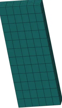
(a) Fuel brick (approx. 1m high) (b) Interstitial brick (approx. 0.3m high)
(e) Loose bearing key (approx. 0.3m high) (f) Spacer key (approx. 0.3m high)
Figure 1. Graphite components.
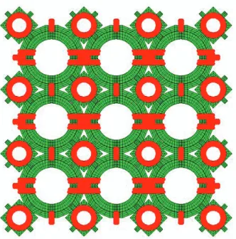
A typical 3x3x3 CBNA model is shown in Figure 2. This model includes 27 fuel bricks, 48 interstitial bricks, 324 filler keys, 72 loose bearing keys, and 216 spacer keys. The array model was meshed with the element type of C3D8R provided in the finite element software Abaqus (2012). In terms of the stresses and contact forces, the size of the array was shown to be appropriate when only one axial crack was present in the central fuel brick.
Figure 2.3D 3x3x3 array model assembly using the graphite components.
Layer 4 Layer 5 Layer 6
Boundary Conditions
The boundary conditions were applied to the array model such that components that bound the array in the X direction are held in X at a limited number of nodes on a symmetry plane; the components that bound the array in the Y direction are held in Y at a limited number of nodes on a symmetry plane; with components on the bottom of the array held in the Z direction at a limited number of nodes at the lower face. In addition, these held nodes were embedded in the components, rather than on the surfaces, to avoid conflicts with the surface contact definition, as shown in Figure 3.
Figure 3. Boundary conditions used in the 3x3x3 array model.
External Load
As the 3x3x3 array only models bricks in layers 4, 5, and 6 of a graphite reactor core composed of 12 layers, the axial load accounting for the weight from layers 7 to 12 plus the Upper Neutron Shield (UNS) was evenly applied to areas of the components on the top of the array i.e., the fuel bricks, interstitial bricks and spacer keys. Figure 4 shows the top view of the array where the loaded areas are highlighted in red.
Figure 4. Applied load on top of the 3x3x3 array model.
Fixed in X direction
Fixed in Y direction Fixed in X
direction
Contact Interaction
The contact interactions due, for example, to the thermal expansion and crack opening were described by a general contact option provided in the finite element software ABAQUS (2012). With this option, the contact interactions between graphite components were automatically included in the analysis.
In addition, two types of contact damping forces were employed in the CBNA model: a global contact damping and locally applied dashpot damping. The basic principle is to apply damping forces to local regions that develop instabilities, and smooth the discontinuity in response, so that a converged solution can be obtained. In the 3x3x3 CBNA model analysis, a global contact damping with optimised coefficients and a dashpot damping approach with a stiffness of 0.2 were used utilising Abaqus DASHPOT1 elements. For each component, at least two dashpots were needed to hold the components in both x-direction and y-direction to ensure the stability of the array model.
Axially Cracked Brick
An axial crack can be inserted into a FE model of a fuel brick through element definition and the use of additional nodes. The crack can be inserted at the beginning of the analysis or in the middle of the analysis (by changing the constraints on the crack-face nodes).
In the analysis for the 3x3x3 CBNA model with a cracked fuel brick, a crack was inserted at 20 full power years (fpy). The crack was located at the loose keyway root (aligned with an end face key/keyway) of the central fuel brick through the radial direction and extended the full length of the fuel brick and split an end face key (see Figure 5).
Figure 5. Cracked central fuel brick used in the 3D CBNA model.
Material Properties and Field Variables
that, within a layer, components of the same type have the same field variables. Note that the field variables used in the work were for development purposes, and may be modified for future (more detailed) investigation.
APPLICATION
One important application of the CBNA model described above is to assess the secondary cracking times for graphite bricks and other graphite components during the operating period following the introduction of an axial crack in the central fuel brick. In particular the contact loads and component stresses at the following main features can be examined:
• End-face key or keyway cracking (fuel bricks)
• Loose bearing key and interstitial key cracking
• Filler key and spacer key cracking
• Keyway root cracking (fuel bricks)
• Bore cracking (fuel bricks)
• Spacer key/loose key/filler key passing into crack due to the crack opening
The contact loads and component stresses at these main features have to be compared with some ‘critical
loads’ and ‘strengths’. Generally, these critical loads and strengths are obtained from un-irradiated graphite material mechanical tests. The effects of irradiation on strength are taken into account by the strength modification factor, which is calculated in the FE analysis by the material subroutine UMAT. The critical loads for un-irradiated materials are scaled by the strength modification factors:
factor on modificati strength
load critical ed
unirradiat load
critical
Irradiated = ´ (1)
For the strengths (i.e., critical stress) at keyway roots and the brick bore, a further modification may be needed if the stresses obtained from the FE analyses are not from a converged mesh. The converged stresses are difficult to obtain with the present CBNA FE analysis because the mesh is not sufficiently refined. Therefore, the un-converged stresses obtained from the CBNA model are scaled using the converged to un-converged ratio obtained from the previous work where a refined mesh of a small section of a brick was used. The scaling procedure results in a set of converged stress scaling factors which are used to reduce the strength in order to facilitate the comparison with the stresses from the FE analyses. The reduced strength is multiplied by the strength modification factor to obtain the so called scaled strength:
factor scaling stress converged
factor on modificati strength
strength ed
unirradiat strength
Scaled = ´ (2)
Equation 2 is applied to the stresses at keyway roots on the fuel bricks. For stresses at the bore, a similar but simpler procedure is used where the converged stress scaling factor was calculated based on the peak hoop and axial bore stresses (i.e., no temporal variation). Note that generally the converged stress scaling factor changes with time due to the converged stress change caused by the irradiation.
EXAMPLE RESULT
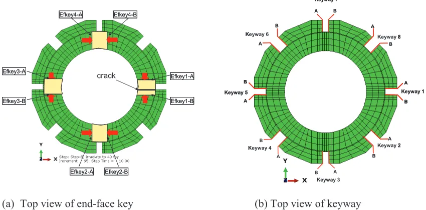
The following example describes an application of the CBNA model in which a full length, full depth axial crack, aligned with one of the loose keyways on the brick was inserted into the central fuel brick at 20fpy (full power years) (see Figure 6 (a) and (b)). The at-power analysis was completed up to 40fpy for the at power condition.
(a) Top view of end-face key (b) Top view of keyway
Figure 6. Notations and labels used in the integrity analysis of the 3D array model.
Figure 7 plots the total model energy (mJ) in the CBNA model. The internal energy (ALLIE) is plotted as the red curve; artificial energy (ALLAE) is plotted as the green curve, the stabilization damping energy (ALLSD) and viscous damping energy (ALLVD) are plotted as pink and blue curves, respectively. The total artificial energy (ALLAE, ALLSD and ALLVD) is a small portion (~7%) of the internal energy, which indicates that the artificial energy does not introduce significant errors and a sensible numerical solution can be obtained.
Figure 7. Total model energy for the at power condition. Efkey1-A Efkey1-B Efkey3-A Efkey3-B Efkey2-A Efkey2-B Efkey4-A Efkey4-B crack Efkey1-A Efkey1-B Efkey3-A Efkey3-B Efkey2-A Efkey2-B Efkey4-A Efkey4-B crack Keyway 3 Keyway 7 Keyway 1 Keyway 2 Keyway 4 Keyway 5
Keyway 6 Keyway 8
A B A B A B A B A B B A B A B A Keyway 3 Keyway 7 Keyway 1 Keyway 2 Keyway 4 Keyway 5
Keyway 6 Keyway 8
A B A B A B A B A B A B A B A B A B B B A B B A B A B A 0.0E+00 2.0E+06 4.0E+06 6.0E+06 8.0E+06 1.0E+07 1.2E+07 1.4E+07 1.6E+07
0 10 20 30 40 50
E n e rg y ( m J ) Time (fpy)
Total model energy for at power
ALLIE
ALLAE
ALLSD
Figure 8 plots the contact loads on both faces of end-face key 1 on the bottom of the cracked central brick with a crack inserted at 20fpy. It can be seen that the contact loads build up steadily after 20fpy when the brick cracks. The loads reach 6.6kN on both faces A and B by 40fpy and it is possible that the brick will experience secondary cracking at the split end-face key.
Figure 8. Contact loads at end-face key 1A and 1B on the cracked central fuel brick.
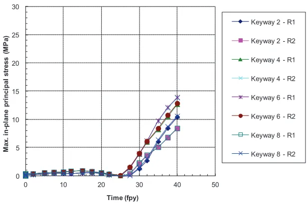
Figure 9 (a) and (b) plot the maximum in-plane principal stress (MPa) at the loose keyway roots and the interstitial keyway roots on the cracked central fuel brick over the operating time for a crack insertion time of 20fpy. The stresses rise rapidly after 25fpy, after the crack has been introduced at 20fpy. It is possible that the rising stresses result in secondary cracking at a keyway root.
(a) Loose keyway root
0 2 4 6 8 10
0 10 20 30 40 50
C on ta c t Lo a ds ( k N ) Time (fpy)
End-f ace key-1A
End-f ace key-1B
-5 0 5 10 15 20 25 30
0 10 20 30 40 50
M a x . in -pl a ne pr inc ipa l s tr e s s ( M P a ) Time (fpy)
Keyway 1 - R1
Keyway 1 - R2
Keyway 3 - R1
Keyway 3 - R2
Keyway 5 - R1
Keyway 5 - R2
Keyway 7 - R1
(b) Interstitial keyway root
Figure 9.Maximum in-plane principal stress at the loose keyway roots and the interstitial keyway roots.
CONCLUSION
A 3D “Cracked Brick Neighbourhood Array” (CBNA) model has been developed which is capable of modelling interacting graphite components undergoing deformation induced by irradiation when an axially cracked fuel brick is present at the array centre. Integrity assessment of the AGR graphite components can be carried out by comparing the featured loads/stresses with the capacities from the feature strength tests.
The example results show that the loads/stresses can rise rapidly after the brick cracks, which implies further cracking could happen during the remaining operation period.
Note that the 3D CBNA model was not sufficiently refined to capture the detail of the strains arising in the vicinity of corners of the end-face keys or keyways. The results could be sensitive to future updates to creep model formulations. Further work would be required to determine whether there are excessive distortions and whether such strains could exceed a critical creep strain.
ACKNOWLEDGEMENT
The support of EDF Energy Generation in the production of this work is acknowledged. The views expressed are those of the authors, and not necessarily those of EDF Energy Generation.
REFERENCES
Dassault Systemes (2012). ABAQUS Software and User Manuals Version 6.12, USA.
0 5 10 15 20 25 30
0 10 20 30 40 50
M
a
x
.
in
-p
la
n
e
p
ri
n
c
ip
a
l
s
tr
e
s
s
(
M
P
a
)
Time (fpy)
Keyway 2 - R1
Keyway 2 - R2
Keyway 4 - R1
Keyway 4 - R2
Keyway 6 - R1
Keyway 6 - R2
Keyway 8 - R1