ABSTRACT
CHAKRABORTI, PARTHASARATHI. Development of a Refreshable Braille Display using Silicone Tubular Dielectric Elastomer Actuators (DEA). (Under the direction of Dr. Tushar Ghosh).
A refreshable Braille cell prototype has been developed based on silicone tubular dielectric elastomer actuator. A refreshable Braille cell consists of series of dots (made up of small metals or plastic pins) which could be vertically elevated or lowered mechanically or electronically or through any other mechanism. A particular permutation of dots in the elevated and contracted position symbolizes a particular character or alphabet. For the purpose of this research, commercially available silicone tubes were used with wall thickness in the range of 100-200 microns. These tubes were inflated with the calcium chloride solution which also acted as the inner compliant electrode for the actuator. The inflation of the tube served to introduce biaxial pre-strain in the tube. The biaxial pre-strain served to increase modulus along the circumferential direction and hence, imparted anisotropy to the tube. The tube was painted with carbon grease on the outside which acted as the outer compliant electrode. The actuation of the tube was characterized by studying parameters such as actuation displacement and the percentage actuation strain, the actuation blocking force, and the time response of the actuator.
Development of a Braille Prototype Actuator using Silicone Dielectric Elastomer Actuator
(DEA)
by
Parthasarathi Chakraborti
A thesis submitted to the Graduate Faculty of
North Carolina State University
in partial fulfillment of the
requirements for the degree of
Master of Science
Textile Engineering
Raleigh, North Carolina
2010
APPROVED BY:
_______________________________
______________________________
Dr. Tushar K. Ghosh
Dr. Maury Balik
Committee Chair
Minor Representative
________________________________
Dr. Russell E. Gorga
DEDICATION
BIOGRAPHY
ACKNOWLEDGMENTS First and foremost, I would like to thank God.
I offer my heartfelt gratitude to my advisor, Dr. Tushar K. Ghosh, who has provided me with his support in terms of knowledge and patience throughout my project and has been forthcoming with novel ideas and suggestions. I owe my accomplishment of Masters’ degree to his unflinching
encouragement and motivation.
I extend my gratitude to Dr. Paul Franzon for his continued encouragement towards my work and efforts. A special note of thanks to Dr. Neil DiSpigna for his invaluable guidance, suggestions and support. I would like to thank Dr. Maury Balik for agreeing to be in my committee as a minor representative and providing useful insights. In addition, I appreciate the willingness of Dr. Russell E. Gorga to serve as a member on my committee.
I am grateful to Mr. Hai Bui and Mr. Dzung Nguyen (Win) for their prompt assistance whenever required. I also acknowledge the help and support of my labmates. I would like to cherish the friendship of Aylin who has been an invaluable mentor besides being an elder sisterly figure. Saral, Krishna, Enes, Arjun and Pruthesh, thanks for being there and helping me all throughout. I would also like to thank my friends- Nags, Logu, Ozan, Lalith, Madhusudan and other friends from India who kept me laughing all throughout my stay here and made me feel at home, while, being away from home. Special thanks to Ms. Angie Brantley for her help and coordination and making sure that I don’t miss
any deadline.
TABLE OF CONTENTS
LIST OF TABLES………...………..……….……….vi
LIST OF FIGURES……….………vii
1. INTRODUCTION ... 1
2. BACKGROUND ... 3
2.1 Braille Display for the Visually Handicapped ... 3
2.2 Refreshable Braille Display ... 4
2.3 Electroactive Polymers ... 5
2.4 Dielectric Elastomers ... 16
2.5 Dielectric Elastomeric Devices ... 30
2.6 Braille Cells Based on EAP and Other Materials ... 41
3. RESEARCH OBJECTIVE... 57
4. BRAILLE CELL DESIGN ... 58
5. MATERIALS AND METHODS ... 60
5.1 Materials ... 60
5.2 Evaluation of DE Tubular Actuator ... 61
5.3 Performance of Braille Cell ... 63
5.3.1 Measurement of Tip Displacement ... 65
5.3.2 Measurement of Blocking Force ... 66
5.3.3 Measurement of Time Response ... 67
6. RESULTS AND DISCUSSIONS ... 70
6.1 Actuation Strain in DE Tubular Actuators ... 70
6.2 Braille Tip Displacement ... 76
6.3 Blocking Force ... 80
6.4 Time Response... 83
7. CONCLUSION ... 88
8. FUTURE WORK ... 90
REFERENCES ... 91
LIST OF TABLES
Table 1: Dimensions in Braille ... 4
Table 2: Comparison of EAPs with other inorganic actuator technologies ... 6
Table 3: Classification of EAPs ... 6
Table 4: Actuation properties of Ferro-electric Materials... 9
Table 5: Actuation properties of CNTs ... 12
Table 6: Actuation properties of conducting polymers ... 14
Table 7: Actuation properties of IPMC based actuator [26] ... 16
Table 8: Comparison of natural muscle and man-made actuator technologies ... 17
Table 9: Comparison of the actuation properties of Silicone and VHB ... 21
Table 10: Measured performance of various dielectrics... 21
Table 11: Actuation strain response of DEAs under pretension ... 27
Table 12: Summary of the electrodes that could be used with DEA ... 30
Table 13: State of the art actuation technologies employed in Braille cell ... 56
Table 14: Braille Cell Metrics ... 59
Table 15: Properties of the silicone tubular DEA ... 60
Table 16: Wall Thickness of the tube for different combination of radial and axial pretensions ... 75
Table 17: Summary of the axial actuation strain experiments ... 76
Table 18: Summary of the tip displacement experiments ... 78
Table 19: Blocking force as a function of tube dimensions ... 83
LIST OF FIGURES
Fig.1: Schematic of Braille ... 3
Fig.2: Molecular depictions of PVDF, an electrostrictive ferroelectric polymer. The β phase (with an all-T conformation) is responsible for ferroelectricity, whereas the α phase (with both T and G conformations) promotes paraelectricity ... 8
Fig.3: Actuation strain as a function of electric field for PVDF–TrFE with different types and concentrations of dielectric materials ... 9
Fig.4: Schematic representation of a cross linked LC elastomer ... 10
Fig.5: Schematic of a CNT ... 11
Fig.6: Actuation mechanism of CNTs ... 12
Fig.7: Structures of three conducting polymers used as actuators ... 13
Fig.8: Expansion of polypyrrole as it is oxidized followed by the subsequent influx of anions (A-) to balance the charge ... 13
Fig.9: Actuation mechanism of an IPMC based actuator ... 15
Fig.10: Tactile output device based on self-switching bi-stable IPMC actuators ... 16
Fig.11: Schematic illustration showing the operational principle of D-EAPs. ... 18
Fig.12: Structure of PDMS ... 19
Fig.13: Circular experimental setup used to measure the electromechanical behavior of D-EAPs in the presence of an electric field and corresponding optical images ... 23
Fig.14: Actuation behavior of silicone dielectric elastomer based prototype fiber actuator over multiple actuation cycles in terms of change in loads over multiple actuation cycles ... 24
or length, (b) lateral area, and (c) transverse, (d) Dependence of blocking stress on
actuation strain for various electroactive materials and systems ... 28
Fig.17: Planar Actuator Configurations (a) bimorph and unimorph (b) stretched film based EAP electromechanical transducer (c) diaphragm (d) extender (e) Linear motion stretched film (f) circular motion stretched film (g) embedded flexible frame actuator (h) bow-tie (i) DEA diaphragm based loudspeakers (j) Diaphragm DEA to control the acoustics or control the roughness of a surface ... 31
Fig.18: A 2-DOF spring roll (a) a compressed central spring on which two highly pre-strained acrylic films (3M VHB 4910) are patterned with rectangular electrode areas (b) the electrode areas stack on top of each other while rolling over the compressed spring core (c) Sushi roll fabricated using four 2 DOF MERs in relaxed state (d) sushi roll in activated state ... 33
Fig.19: DEA based robots (a) FLEX-2 robot (b) Skitter Robot using 6 rolled actuators (c) MERbot-a six legged robot with 2-dof spring rolls as legs ... 33
Fig.20: A schematic of cylindrical DEA ... 34
Fig.21: Axial actuation strains as a function of applied electric field in uniaxially pre-strained silicone tube based DEA ... 35
Fig.22: Change in load on the load cell as a function of applied electric field in uniaxially pre-strained silicone tube based DEA ... 35
Fig.23: A multi-stack like actuator ... 36
Fig.24: Working of a helical actuator ... 36
Fig.25: Working of a rolled actuator... 37
Fig.26: Circular rolled actuator ... 37
Fig.28: Schematic of a static tactile display ... 38
Fig.29: (a) Deformation of multilayer DEA stack in thickness direction on application of electric voltage (b)Electrical equivalent circuit of multilayer DEA ... 39
Fig.30: Actuation modes of the proposed actuator (a) bias turned off (b) bias turned on ... 40
Fig.31: Proposed tactile display device (a) exploded layout and cross sectional view of the tactile device (b) assembly picture of the tactile cell ... 40
Fig.32: Plot of Braille tip displacement Vs applied voltage ... 41
Fig.33: A piezoelectric Braille cell ... 41
Fig.34: Schematic of the piezoelectric bimorph based Braille cell ... 42
Fig.35: Mechanism of actuation in a piezoelectric bimorph based Braille cell ... 42
Fig.36: (a) Displacement response of the piezoelectric bimorph (b) Response of the tip displacement to the touching force ... 43
Fig.37: (a) Hydraulic and Latching (HL) PVDF Braille cell; and (b) Actuation sequence ... 44
Fig.38: (a) PVDF-PTrFECFE actuator with a spin core inside it (b) Schematic diagram of fabrication process of the rolled EAP actuator for Braille display using the electrostrictive polymer thin films: (a) pre-strained spring core, (b) electroded polymer thin film, (c) the thin film is folded to form a bilayer to separate the positive and negative ends, and (d) the rolled actuator ... 45
Fig.39: Displacement of the Braille tip displacement Vs Electric field. The tip demonstrates the required displacement of 0.5 mm at an electric field of 60 KV/mm ... 45
Fig.40: (a) Components in a SMA based Braille cell (b) SMA based Braille cell assembly ... 46
Fig.41: Braille Display based on SMA coil actuator and magnetic latch mechanism ... 47
Fig.42: Cross sectional view of an ERF based Braille dot ... 48
Fig.44: (a) Polypyrrole (PPy) based Braille cell with 8 pins (b) schematic of a single
PPy based Braille ... 50
Fig.45: Schematic of a Braille cell based on polymer gels ... 51
Fig.46: Braille Cell based on magnetic latch ... 52
Fig.47: Working of the magnetic latch ... 52
Fig.48: Mechanism of the dot rising in a Braille cell based on ball latch mechanism ... 53
Fig.49: Design concept of a Braille mouse ... 54
Fig.50: Schematic of a Braille cell based on rotary cam movement ... 55
Fig.51: (a) Design of the Braille cell based on silicone tubular DEA (b) the Braille actuator in ‘down‘ position when there is no electrical excitation, and,(c) the Braille actuator in ‘up’ position when electrically excited ... 58
Fig.52: (a) Load-Strain curve for 25 cycles for silicone DEA tube (b) Plot of modulus Vs Axial Strain for the 1st and the 25th cycle ... 62
Fig.53: Schematic of the Scaled up beta version of the proposed Braille cell ... 63
Fig.54: Schematic of the blocking force experiment ... 66
Fig.55: Circuit diagram of the Bertan High Voltage power supply Series 225 ... 67
Fig.56: Circuit diagram of the Bertan High Voltage power supply Series 225 with an external resistor connected in parallel ... 69
Fig.57: Voltage ramp applied for the actuation strain experiments ... 70
Fig.58: Axial Actuation Strain and Boundary displacement as a function of electric field for different radial and axial pretensions ... 71
Fig.61: Braille Tip Displacement as a function of electric field for different radial and
axial pretensions ... 77
Fig.62: Braille Tip Displacement as a function of electric voltage for different radial and axial pretensions ... 78
Fig.63: Braille Tip Displacement as a function of electric field for 90% radial and 43.4% axial pretension ... 79
Fig.64: Displacement of the Braille tip observed over multiple actuation cycles of the silicone tubular actuator ... 80
Fig.65: Actuation blocking force produced in silicone tubular DEA as a function of electric field ... 81
Fig.66: Blocking force of the tube as is it cycled 10 times from 0 to 117 KV/mm ... 82
Fig.67: Timeline of the time response experiments ... 83
Fig.68: Strain-Time response of the silicone DEA ... 84
Fig.69: Strain response over multiple cycles for different frequencies ... 85
Fig.70: Schematic showing the sequence of actuation over multiple cycles ... 86
Fig.71: Flow chart describing the reason for decrease in normalized actuation strain over multiple cycles on increasing the frequency of actuation ... 87
Fig.72: Proposed silicone DEA based Braille prototype with a spring core ... 90
Fig.73: Snapshot of Braille tip displacement on application of electric bias ... 100 Fig.74: Flow chart depicting the sequence of functions used in Image Acquisition Program
in Labview ... 101
Fig.75: Snapshot of Image acquisition sequence in Labview(a) using IMAQdx Open camera,
IMAQ create, IMAQ ConFig Grab and IMAQ Grab (b) IMAQ AVI write ... 102
Fig.77: J107 connector jack on the rear panel of power supply ... 103
Fig.78: Connector Board CB-68LP ... 103
Fig.79: Inputting of the text file to the DAQ card and the subsequent generation of analog
1. INTRODUCTION
Braille characters are different arrangements of raised dots used by visually impaired people to read through tactile sensation. A Braille character consists of six or eight dots in a rectangular array of 3×2 or 4×2 where each combination of elevated and down position of the dots produces a specific sensation on the finger tips representing various letters and numerals [1]. It can be used as an interface for the visually impaired people to read electronic media such as e-mails and browse websites among other things [2].
According to World Health Organization data, there are approximately 314 million people globally who are visually impaired among which about 45 million people are completely blind [3]. Tactile and auditory sensations are the most important form of communication for the visually impaired people with the outside World [4]. The tactile sensation is felt by the human body through the displacements and/or the forces generated by the tactile devices at the contact points with the human being, thus, stimulating the human skin [5]. The tactile device has been conceived to be used as an inexpensive refreshable dynamic Braille cell. Nonetheless, the development of a full-page, portable, low cost, refreshable Braille display has been referred to as the ‗Holy Grail‘ of assistive technologies for the
The use of various actuator technologies and materials for their use in tactile displays such as Braille cells has been the subject of investigation for many years. Braille cells have been developed based on a host of technologies, some of them being electromagnetic [9, 10, 11], pneumatic [12, 13], and shape memory alloys [1, 2, 15]. However, there are issues that limit the commercial viability of these technologies. Some of these issues are complex driving electronics, inefficient power usage, and limited mobility [1, 8, 10, 17]. Recently, Electroactive Polymer (EAP) based materials have been used in powering the Braille dots in the Braille cell displays. The materials which have been evaluated include conducting polymers, dielectric elastomers [4, 8, 64], ferroelectric, ionic polymer metal composite (IPMC), and polyvinylidenedifluoride (PVDF) [6, 8, 9, 18]. These actuators have been designed in various configurations such as a Dielectric Elastomer Actuator (DEA) film that is rolled around a pre-strained spring, a bi-morph configuration, shaped as a multi-layered array, or consisting of a pre-strained diaphragm with a series of spring-backed element with the aim of developing miniature actuated pins/dots that can be packed into a small area while generating the required displacement and force [8]. Among the EAP materials evaluated, DEA offers advantages in actuator construction and fabrication in terms of excellent flexibility with comfortable softness, ease of fabrication, miniaturization, and cost effectiveness [19, 17]. Still there are certain issues which cap their commercial viability and hence future research should focus on improvements in the materials and designs of such Braille cell actuators [19]. For instance, efforts should be expended in making the electronic EAPs operate under low bias or research studies could be aimed on making IPMCs generate more displacement and blocking force [3, 4].
2. BACKGROUND
Recently, a lot of research has been carried out in the area of refreshable Braille displays using Electroactive Polymers (EAPs) as an actuator. This section gives an introduction to the Braille displays and the refreshable Braille displays followed by a brief account of the different types of electroactive polymer actuators with a special focus on Dielectric Electroactive Polymers and their use as actuators. The section ends with a brief comparison of the relative merits and demerits of the various mechanisms used to power a Braille cell and the potential of dielectric elastomer as an actuator for application in Braille cell.
2.1 Braille Display for the Visually Handicapped
As mentioned before, Braille characters are different arrangements of raised dots used by visually impaired people to read through tactile sensation [1]. It was invented by Louis Braille in 1824 at the age of 15. The spacing between the different dots and cells in a multiline Braille display follow certain set of specifications which may vary across geographies.
Fig.1 shows the sketch of a Braille and Table 1 shows the dimensions used for Braille as per the standard specifications set by the American Library of Congress.
Table 1: Dimensions in Braille [20]
2.2 Refreshable Braille Display
A refreshable Braille cell display consists of series of dots which could be vertically elevated or lowered mechanically or electronically or through any other mechanism. A particular permutation of dots in the elevated and contracted position symbolizes a particular character or alphabet. Users can read these characters with their fingers. There are usually 40, 65, or 80 arrays (characters) per line of text [21]. A refreshable Braille display is usually connected to a computer and it works in combination with a screen reader. The users provide inputs to the computer with the help of a Braille keyboard and access the output in the Braille cells through a Braille displayer. The refreshable Braille displays are generally positioned below the keyboards so that the users could easily access the Braille cells along with the keyboard [7].
The refreshable Braille displays have come up a long way from the time of electromechanical actuator based displays based on solenoids, developed by Mr. Schaefer and marketed by Maryland Computer Services way back in the mid-1970s [22]. On passing an electric current through a solenoid, the magnetic field forced the solenoid rod to pull an actuator which raised/lowered the Braille tip [23]. There were issues of higher power consumption associated with it. To avoid power consumption, the pins were permanently kept in a raised position implying that the readers could not touch the display while it was refreshing. In the late 1970s, the idea of Braille displays based on the principle of piezoelectricity was introduced by Oleg Tretiakoff [22, 23]. Application of a potential difference between the opposite faces of the piezoelectric material led to a change in its shape and
Horizontal dot to dot
(mm)
Vertical dot to dot
(mm)
Cell to cell (mm) Line to Line (mm) Dot Diameter (mm) Dot Height (mm)
A b c d e
dimensions which was used to raise and lower the Braille tip. These Braille cells had less power consumption and at the same time were less expensive to produce. In addition, the readers could touch the display while it was refreshing [23]. Arguably, this became one of the first commercially available refreshable Braille displays used by the visually impaired people. In 1980s, the Tieman Group pioneered the development of Braille cells improving the feel and the portability of the Braille cells. Since then, the Piezoelectric based Braille cells have continued to dominate the refreshable Braille display market [23]. The piezoelectric based Braille cells have been further engineered and developed to bring their cost down from 100 $ a cell in the mid-eighties to currently 35$ a cell [22]. However, it is being argued that other EAP technologies such as Dielectric Elastomer Actuators offer better properties such as very high linear actuation strain, high energy density, lower mass density, and, ease of fabrication among others [24]. The following and the subsequent sections provide an overview on the different EAP technologies and the construction of Braille cells using these technologies with a special focus on Dielectric Elastomer Actuators.
2.3 Electroactive Polymers
Electroactive Polymers (EAPs) are soft, flexible organic materials which respond to external electric field by producing a deformation in their dimensions and shape. They have found increasing applications as actuators due to their mechanical response to the electrical energy [19].
Table 2: Comparison of EAPs with other inorganic actuator technologies [19]
Property Electro Active
Ceramics
Shape Memory Alloys
Electroactive Polymers
Actuation Strain (%) 0.1-0.3 <8 >1 (upto>200)
Blocking Force (MPa) 30-40 ~700 0.1-3
Actuation –speed magnitude (s) 10-6-1 1-102 10-6-102
Mass Density (g/cm3) 6-8 5-6 0.9-2.5
Drive Voltage (v) or Field (V/µm) 50-800 5 2-7 or 10-150
Consumed power magnitude (W) 1 1 10-3
Mechanical Response Fragile Elastic Elastic, Resilient
According to Table 2, Shape Memory Alloys are known to demonstrate high forces and displacements, however, their downsides are slow response times, large mechanical hysteresis and short cycle life. Accordingly, Electro Active Ceramics have quick response time and are compact; however, their application is limited due to their low actuation strain (of less than 1%), high cost and fragility [19]. Table 3 demonstrates the categorization of EAPs into electronic EAPs and ionic EAPs as per their operational mechanism.
Table 3: Classification of EAPs [19]
Ionic EAP Electric EAP
Carbon Nanotubes Ferroelectric Polymers Conductive Polymers (CP) Dielectric Elastomer Actuators (DEA) Ionomeric polymer metal composites
(IPMC) Electrostrictive graft polymers Ionic Polymers Gels (IPG) Liquid Crystalline Elastomer (LCE) Electrorheological Fluids (EFs) Electro-viscoelastic elastomers
Electronic EAPs are called dry EAPs and they show deformation in their shape and dimension when placed under an external electric field. Ionic EAPs are also called wet EAPs and they deform by movement of ions across them.
muscles. Other DEAs which are being investigated include nanostructured block copolymers with customized composition [19]. They have been discussed in detail in later sections.
As mentioned before, EAPs are a class of material which respond to electrical simulation by producing a mechanical strain. They are classified into 2 types: electronic and ionic EAPs
Electronic EAPs
They are driven by electric field. The most commonly known electronic EAPs are ferroelectronic EAPs, DEAs, LCEs, electrets, electroviscoelastic elastomers and electrostrictive polymers. They have been described in the subsequent sections.
Ferroelectric polymers
Ferroelectric materials in general are labeled as the electrostatic analog of ferromagnets [3]. They are also called electrostrictive materials [26]. The phenomenon of ferroelectricity is referred to as spontaneous polarization in certain types of non conducting crystal or dielectric material called ferroelectric crystals. These crystals show an elongation when placed under an external electric field or produce an electric voltage when they are placed under strain [17]. The materials which have been investigated for use as actuators include polyvinylidene fluoride (PVDF), poly (vinylidene fluoride co- trifluoroethylene) (PVDF–TrFE), polyvinyl fluoride (PVF), odd-numbered nylons (with odd numbered
carbon atoms between amide groups) and polyurethane [17, 19]. Among ferroelectric polymers, poly(vinylidene fluoride—trifluoroethylene), abbreviated as P(VDF-TrFE), and its co-polymers have
field, the conformation transforms to a mixture of trans and gauche phases. This causes change in lattice dimensions which eventually translates into actuation strain [19].
Fig. 2: Molecular depictions of PVDF, an electrostrictive ferroelectric polymer. The β phase (with an all-T
conformation) is responsible for ferroelectricity, whereas the α phase (with both T and G conformations)
promotes paraelectricity [19]
The major disadvantage associated with the ferroelectric materials is that they exhibit hysteresis [26]. Hence, an opposite electric field has to be applied across the ferroelectrics to reverse the induced polarization. This leads to energy loss. The above mentioned hysteresis could be minimized by lowering down the Curie temperature (temperature above which the thermal energy supplied to the polymer is sufficient to disrupt the permanent polarization within the material) of the ferroelectric [26, 27]. This could be essayed by inducing some imperfection in the ferroelectric which will disrupt the long range correlations between the polar groups [26, 27, 28]. Fig.3 below demonstrates the increase in actuation strain in the ferroelectric polymers as square of the electric field applied. Ferroelectric polymer based actuators could generate maximum actuation strains of 7% at high electric fields of approximately 150 MV/m, with work densities approaching 1 MJ/m3 at a stiffness of more than 0.4 GPa [26].
Fig. 3: Actuation strain as a function of electric field for PVDF–TrFE with different types and
concentrations of dielectric materials [19]
Table 4 below shows some of these properties. However, such actuation mechanisms require high voltages (>1KV). In addition, this technology poses challenges in the form of heat dissipation which renders achievement of frequencies above 100 Hz as impossible [4, 27, 28].
Table 4: Actuation properties of Ferro-electric Materials [26, 28, 29]
Property Typical Maximum
Strain (%) 3.5 5
Stress (MPa) 20 45
Work Density (KJ/m3) 320 >1000
Strain Rate (%/s) >2000 @ 10Khz
EM Coupling 0.1-0.2
Modulus (GPa) 400 1200
Applied Potential (V) >1000
Max Electric Field
(KV/mm) 13 150
Dielectric Constant 55 Temp Dependent
Temperature range (oC) 60
addition of copper phthalocyanine to a P(VDF-TrFE) matrix because the dielectric constant increased from approximately 50 to more than 400 [28,30,31].
Liquid Crystalline Elastomers (LCEs)
LCEs are anisotropic systems that combine the properties of liquid crystalline (LC) phases with rubber elasticity. They are prepared by incorporating mesogens (molecules with anisotropic forms) into polymeric systems [32]. Fig.4 shows a typical cross linked elastomer.
Fig. 4: Schematic representation of a cross linked LC elastomer. [32]
These mesogens can exist in one of the thermodynamically stable LC phases in a temperature range between the crystalline phase and the isotropic melt [32]. These phases are categorized into the nematic phase, for which the long range order is caused by the parallel orientation of the mesogenic groups, and smectic phases, where the molecules are additionally arranged in layers [32].
Dielectric Elastomer Actuator (DEA)
They belong to a class of EAP that produce an electromechanical response on being exposed to electrical field. Since, the thesis deals with developing a refreshable Braille cell based on DEA, this topic has been provided with a more exhaustive treatment in a separate section.
Ionic EAPs
They show deformation by movement or migration of ions. The most commonly known ionic EAPs are ionic polymer gels, IPMCs, conducting polymers, carbon nanotubes actuators and electrorheological fluids.
Carbon Nanotubes (CNT)
They are hexagonal network of covalently bonded atoms which roll up to form a seamless cylinder as
shown in Fig.5 below [34]
.
There are two types of CNTs – Single Wall Carbon Nanotubes (SWCNT) and Multi Wall Carbon Nanotubes (MWCNT) [12]. They have lengths in the micrometer scale. The diameters of such tubes vary in the range of 1nm to 100 nm depending on the type of CNT [17, 26]. They aggregate into bundles due to van der Waals forces. Bundle diameters of 10 nm are typically used for actuation studies [17].Fig. 5: Schematic of a CNT [87]
leading to actuation strain [19, 26]. The schematic in Fig.6 below intends to demonstrate the actuation mechanism in the CNTs.
Fig. 6: Actuation mechanism of CNTs [19]
Table 5 below mentions some of the properties of the CNTs.
Table 5: Actuation properties of CNTs [26, 32, 35, 36]
Property Minimum Typical Maximum
Strain (%) 0.2 ~1 >1
Stress (MPa) 1 27 20000
Work Density (KJ/m3) 2 40 3-104
Power (W/kg) 10 270 1010
Life (cycles) 33% reduction in strain over 140000 cycles at 1 KHz
Coupling (%) 0.001 0.43
Modulus (GPa) 1 (paper) 10 (fiber) 640 (single tube) Applied Potential (V) 1 30 (fast actuation)
Cost (USD/kg) <<50000 500000
Conducting Polymers
Fig. 7: Structures of three conducting polymers used as actuators [26]
The actuation mechanism in conducting polymers works on the principle of exchange of ions between the polymer chains and the electrolyte [17, 19, 26]. The change in the oxidation state induced by electrochemical changes triggers redox reactions which causes the addition or removal of ions from these structures to balance the charge on it. This is one of the major reasons responsible for the dimensional changes in the structure [19, 26]. Fig.8 demonstrates the mechanism.
Fig. 8: Expansion of polypyrrole as it is oxidized followed by the subsequent influx of anions (A-) to
balance the charge. [26]
In addition, the conformational changes in the backbone and the subsequent flux of solvent also contribute towards the actuation mechanism in the conducting polymers [37, 38].
actuator at high current and, subsequently, high power putting constraints on the power supply. The strains achieved by the actuator are in the range of 2% and therefore, need to be mechanically amplified for autonomous applications [26]. In addition, the strain rate produced by the actuator is less than 12% per second as a result of the internal resistance of the electrolytes and the chains of the conducting polymers and by the low ionic diffusion rates inside polymer [26].Table 6 demonstrates the actuation properties of conducting polymers.
Table 6: Actuation properties of conducting polymers [26, 37, 38, 39, 40]
Property Minimum Typical Maximum
Strain (%) 2 12
Stress (MPa) 5 34
Work Density (KJ/m3) 100
Strain Rate (%/s) 1 12
Power (W/kg) 150
Life (cycles) 28000 800000
Coupling (%) 0.1
Modulus (GPa) 0.2 0.8 3
Tensile Strength (MPa) 30 120
Applied Potential (V) 1.2 10
Charge Transfer (C/m3
or C/m2) 10
7
108
Cost (USD/kg) 3 1000
Ionic Polymer Metal composites (IPMC)
The major factors affecting the actuation behavior in IPMCs include the type of polymer matrix used, the counter ions, the amount of solvent present [42], quality of metallization [45], the thickness of the IPMC film [41] and the surface area of the polymer membrane [26].
Table 7 tabulates the actuation properties of the IPMC.
Table 7: Actuation properties of IPMC based actuator [26]
Property Minimum Typical Maximum
Strain (%) 0.5 3.3
Stress (MPa) 0.23 3 15
Work Density (KJ/m3) 5.5
Strain Rate (%/s) 3.3
Power (W/kg) 2.56
Coupling (%) 3
Modulus (GPa) 0.05 0.1
Density (kg/m3) 1500
Applied Potential (V) 1 1-4 7
Charge Transfer (C/m3
or C/m2) 900000 or 900
Cost (USD/kg) 500
They are used in applications such as metering valves, diaphragm pumps, sensors, fins for robotic
fish, artificial flies, tactile output devices, and mechanical grippers [47].
Fig
.10 presents a schematic of a tactile display and a mechanical gripper based on IPMC actuatorsFig. 10: Tactile output device based on self-switching bi-stable IPMC actuators [47]
2.4 Dielectric Elastomers
applications in products such as loudspeakers, etc. As a result, it has been the focus of many scientific researches being carried out in the recent past to explore its hidden benefits [17].
Table 8: Comparison of natural muscle and man-made actuator technologies [25]
DE actuators are simple to design and construct, they can operate over a large temperature range, produce large strains with high electromechanical coupling efficiency [19]. In addition they can produce small displacement at frequency in the range of tens of KHz. Moreover, they can be used as generators and sensors [26].
Principle of Actuation
The principle of actuation in DE films is based on the electrostatic attraction which is developed between the oppositely charged layers of electrodes on application of electric field with the layer of DE sandwiched between them.
Fig. 11: Schematic illustration showing the operational principle of D-EAPs [48]
As shown in the Fig.11, the two electrodes try to come closer to each other on being subjected to a potential difference across the electrodes due to the development of a Maxwell pressure σM [48]. The
Maxwell pressure is calculated as the change in electrostatic energy per unit area per unit displacement in the thickness direction. The dielectric film is assumed to be perfectly elastic [49].The Maxwell pressure is expressed as
2
E
o M
Eq. (1)Where ε is the dielectric constant of the dielectric EAP; E is the applied electric field; and εo is
permittivity of free space.
1
)
1
)(
1
)(
1
(
S
x
S
y
S
z
Eq. (2)The polymer will expand along the X and Y axes due to compression in the Z direction. Actuation is measured along the planar direction in the X and Y direction. Blocking force (Fy) which constitutes the force required to return a fully energized actuator to its original dimension is measured along the x or y direction [26]. The other important characteristics such as strain energy density measure both the stress and strain generation capability of an actuator material [30]. The electromechanical coupling efficiency of an actuator calculates the amount of supplied electrical energy converted into useful mechanical energy [39].
Different DEs have been investigated to evaluate their performance as actuator. Some of them are acrylics, silicone, ethylene propylene, poly-butadiene and its copolymers, isoprene and urethanes. Amongst the abovementioned DEs, Silicone and acrylics have been observed to have the best properties required for actuation [26]. A brief discussion on some of the DEs has been presented below.
Silicones are entirely synthetic polymers containing a repeating Si-o backbone and organic groups attached directly to the silicon atom via silicon-carbon bonds [50]. There are different types of silicones based on the presence of functional groups: dimethyl silicone elastomers (PDMS), vinyl silicone elastomers, phenyl silicone elastomers, nitrile silicone elastomers, fluorosilicone elastomers, RT vulcanizing silicone elastomers, borosilicones and, silicone carbide [50]. The structure of PDMS is shown in Fig.12:
Fig. 12: Structure of PDMS [50]
rubbers [50]. Silicone exists in many structural forms such as linear, branched, cross linked and so on. The combination of their useful properties allows for the existence of fluids, gels and elastomers all made from the same type of polymer; i.e. PDMS. Silicone fluids are usually straight chains of PDMS. Silicone gels are mildly cross-linked PDMS where the crosslink is achieved with vinyl and hydrogen groups on separate silicon atoms in the presence of a catalyst. Silicone elastomers are highly cross linked PDMS fluid gel with little free fluid polymer. In addition, they are also reinforced with silica to provide strength to the silicone elastomer [50].
They have an array of useful properties ranging from high degree of chemical inertness, resistance to weathering, good dielectric strength and low surface tension in addition to thermal and oxidative stability. They exist as molten macromolecules with high degree of flexibility, high free volume and a low glass transition temperature. The silicone films could be easily processed with the help of spin coating or solution casting [50].
The cross link density of the polysiloxanes plays a very significant role in determining the actuation performance of a silicone film. This is because the cross link density influences the elastic modulus which in turn affects the actuation performance. In addition, the chemistry and the molecular weight of the polysiloxanes influence the actuation performance [51]. Silicones have been observed to be highly inert to the environment; they could operate over a greater range of temperatures from -65 to 240 oC [26]; they are less sensitive to environmental degradation. In addition, they have been known to exhibit high electromechanical coupling efficiencies of the order of 63% to 79% [51]. To summarize, the silicones have proved to be an excellent material for use as DE.
and strains of 60-70% along the axes along with a high blocking stress of 7.2 MPa and a corresponding elastic energy density of 3.4 MJ/m3. Finally, they are reported to exhibit the highest electromechanical efficiency of approximately 90% [51, 54]. Table 9 compares the different properties of silicone and acrylic which are being considered as actuators.
Table 9: Comparison of the actuation properties of Silicone and VHB [26]
Property Silicone VHB
Maximum strain (%) 120 380
Stress (MPa) 0.3 (typical)
3.2 (max)
1.6 (typical) 7.7 (max) Work Density (KJ/m3) 10 typical
750 max
150 typical 3400 max
Density (kg/m3) 1100 960
Peak Strain rate (%/s) achieved
at 34,000@12% [email protected]%
Peak Power (W/kg) Taken at peak load of
5000 300 KPa
3600 1.6 MPa
Continuous Power (W/kg) 500 400
Lifecycles at strain with no
failures observed 10
6
@10% 106@50%
EM Coupling (%) 80 (max) 90 (max)
Modulus (MPa) 0.1-1 1-3
Speed of sound (m/s) <30 <55
Thermal Expansion(m/m/oC) 1.8X10⁻⁴
Dielectric Constant @ 1 KHz ~3 ~4.8
Max Field (KV/mm) 110-350 125-440
Temperature (oC) 100 to 250 -10 to 90
Table 10 compares the performances of silicone with other dielectrics.
Table 10: Measured performance of various dielectrics [17]
Polymer Type Energy Density (J/cm3) Pressure (MPa) Strain (%) Young‘s Modulus (MPa) Maximum Electric Field (V/µm) Polyurethane, Deerfield PT61 00S 0.1 1.9 11 17.0 160 Silicone, Dow corning Sylgard 186 0.034 0.21 32 0.7 144 Fluorosilicone Dow Corning 730 0.019 0.07 28 0.5 80
Flouroelastomer Laurenl-143HC 0.008 0.2 8 2.5 32
PolybutadieneAdrich PBD 0.011 0.19 12 1.7 76
Isoprene Natural Rubber 0.0052 0.094 11 0.85 67
into periodic and aperiodic nanoscale sequences of chemically dissimilar units. They microphase-separate into discrete domains in the presence of a non-volatile, midblock- selective solvent [19]. One such tri-block copolymer is commercial poly [styrene-b-(ethylene-co-butylene)-b-styrene] in which the end blocks are glassy and the midblock is rubbery at room temperature. The copolymer demonstrated actuation strain of approximately 250% at an electric field of 22 V/mm, the electromechanical coupling efficiency achieved in such electroactive nanostructured polymers (ENPs) was 92% which is greater than the 90% achieved in an acrylic DE [19,29].
Another type of tri-block copolymer consists of linear bi-component block copolymers with the three blocks covalently linked together. Here, the system can form a 3D network which could be expected to behave as an elastic solid [19]. For instance, segmented polyurethane with crystalline and rubbery blocks has reported both electrostatic and electrostrictive actuation with blocking stress of 1.9 MPa and electromechanical coupling efficiency of 21% [19].
Furthermore, the benefits of the abovementioned two types of tri-block copolymers are that they undergo little actuation hysteresis (<15%) on cycling in addition to providing reasonable actuation without mechanical pre-straining [19]. Finally, their blocking stress is comparable to that of the acrylic DE [19, 29].
Actuation parameters and characterization
The performance of an actuator is characterized by evaluating different parameters. The criticality of the parameter may however depend on the application of the actuator. The most germane ones include actuation strain [55, 56], actuation blocking force [55, 56], response time [55-57] and life cycle testing [55-57, 58] among others.
Actuation Strain
active region of actuator as the actuation strain generated is proportional to the square of the electric voltage applied across the actuators [48, 56, 57]. Finally, the actuation strain is a function of the boundary condition. For instance, the actuator modulus inversely affects the actuation strain of the DEs [17].
Literature studies reveal actuation strains of actuators depend on the type of configuration used for the particular actuator which will be elaborated upon in the subsequent sections [17, 24, 48, 49, 56, 59]. For a planar DE, actuation strains have been reported as strains along X and Y directions under a certain set of pretensions. Silicone and acrylic elastomer based Des have reported actuation strains of 117% and 215% along the axes under isotropic conditions. In addition, literature has reported actuation strain in cross sectional terms as aerial strains. [17, 48]. Fig.13 demonstrates the actuation strain observed in a circular DEA film.
Fig. 13: Circular experimental setup used to measure the electromechanical behavior of D-EAPs in the
presence of an electric field and corresponding optical images [19]
Actuation Blocking Force
which is coupled to the load cell is exposed to a potential difference [17]. The graph presented in Fig.14 shows the drop in force observed over multiple actuation cycles. A vast assortment of studies has revealed the different values of actuation blocking force developed in DEAs. Blocking force depends on the configuration of the actuator (as discussed in details in subsequent sections). For instance, a Multi roll Elastomer, VHB 4910 acrylic polymer film actuator which is rolled over a few layers into 1.4 cm diameter with 6.8 cm axial length and weighing 11g generated a blocking force of 15 N [57]. The same VHB 4910 acrylic polymer film when formed into a bi-layer linear actuator, weighing less than 0.1 g and mounted on a flexible frame developed a blocking force of 1.5 N at 5.5 KV [24]. Studies have demonstrated that the blocking force like actuation strain depends on the type of DEA used as the dielectric constant varies with the material. The blocking force was found to be directly proportional to the dielectric constant of the material and varied as square of the applied potential according to a relationship derived by Kofod, et al [60].
Fig. 14: Actuation behavior of silicone dielectric elastomer based prototype fiber actuator over multiple
actuation cycles in terms of change in loads over multiple actuation cycles [17]
Electromechanical Coupling Efficiency
electromechanical coupling efficiency for acrylic elastomer was observed to be in the range of 60-90% [51, 54].
Strain Energy Density
The strain energy density of a dielectric elastomer actuator measures both the stress and strain generation capability of an actuator material [30]. It is defined as the expended work per actuation cycle per unit volume of actuator, exclusive of overhead peripherals, such as electrolytes, power supplies, counter electrodes and packaging [48]. It is expressed as [48]
)
(
2
/
1
YS
2Y
Eq. (3)Here, U is the strain energy density, Y is the Young‘s Modulus, and S is the actuation strain generated. This equation assumes low actuation strain. For high actuation strain generated, a more useful measure is the electromechanical energy density expressed as [48]
)
1
ln(
S
YS
e
Eq. (4)As can be seen from Table 13, at 300% biaxial pre-strain, VHB 4910 possess the highest strain energy density of 3.4 MJ/m3 as against 0.75 MJ/m3 realized by silicone at 45% biaxial pre-strain.[48] Time Response
The response time of the actuator can be termed as the minimum time required by the actuator to achieve its steady state value of actuation on being subjected to a voltage pulse. The response time of a material is limited which could be attributed to a number of reasons, the germane ones being the dynamics of size and the configuration in addition to the driving electronics [61].
Fig. 15: Strain response due to an electrical stimulus: (a) silicone DC 3481 (b) acrylic VHB F-9473PC [62].
The silicone specimen took 3 seconds to reach the expected strain of 8.5%, whereas, the acrylic took 150 seconds to reach its expected strain of 8.5%. The reason ascribed was the higher viscosity of the acrylic. Pre-straining the acrylic could reduce this viscosity. The pre-straining also enhances the material dielectric strength. However, it also increases the material stiffness and reduces the dielectric constant of the material to some extent [62].
The other limitations could be ascribed to the conductivity of the electrodes including their charging and discharging times.
the modulus increases non linearly with increase in the applied pre-strain [17]. Table 11 shows the strain response of various elastomers when pre-strained under similar conditions:
Table 11: Actuation strain response of DEAs under pretension [48]
Material Prestrain (%)
Relative Area Strain (%) Electric Field (MV/m) Pressure(Mpa) Energy Density (MJ/m3) DC-HS3 Silicone
(68,68) 93 110 0.3 0.098
(14,14) 69 72 0.13 0.034
Nusil CF19-2186 Silicone
(45,45) 64 350 3.0 0.75
(15,15) 33 160 0.6 0.091
3M VHB 4910 Acrylic
(300,300) 158 412 7.2 3.4
(15,15) 40 55 0.13 0.022
As observed from Table 11, an increase in the biaxial pre-strain increases the generated actuation strain.
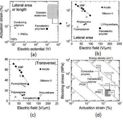
Fig. 16: Comparison of the actuation-strain levels achieved for (a) various EAPs as a function of electric
potential, and (b, c) D-EAPs and a ferroelectric polymer as a function of electric field. The actuation
strains are labeled in each part and include (a) lateral area or length, (b) lateral area, and (c) transverse,
(d) Dependence of blocking stress on actuation strain for various electroactive materials and systems
[19]
generated within the actuator which is depended on the electric voltage applied and the sample thickness. Hence, as seen in Figs 16(b) and (c),DEs such as silicone, acrylic and the copolymer based ENPs have demonstrated the highest actuation strain both in-plane and transverse actuation strains on application of electric field. In addition, these materials possess favorable attributes such as light weight, mechanical resilience, rapid response and high energy density [19].
Fig.16(d) shows that conducting polymers and ferroelectric polymers demonstrate high blocking stress (more than 100 MPa) at lower actuation strain, whereas, DE such as acrylic have exhibited both high blocking stress of between 1 and 10 MPa) and higher actuation strain (>100%). The discrete straight lines represent actuator with similar energy density or stroke work. Actuators such as acrylic, SMA, hydraulic based actuators have higher stroke work since they possess higher energy density, generate higher actuation strain and higher blocking force [19, 55]. They have the potential to be used for biomimetric applications including artificial muscle and micro robotics [55]. They could be also used in micro fluidic and haptic devices requiring lateral or transverse extension [19]. DEs such as acrylics and the ENPs also exhibit the best electromechanical efficiency so far among the EAPs with acrylics demonstrating electromechanical coupling efficiency of about 92% [19, 26]. On another note, CPs and DEs have very small response times of the order of milliseconds while human muscles and SMAs require response times of more than two orders of magnitude [19].
Electrodes used in DEA
Table 12: Summary of the electrodes that could be used with DEA [61]
Electrode
Resistivity (milli-ohms cm)
Application Advantages Disadvantages
Carbon grease Thin film deposition Commercially available; good electromechanical coupling efficiency
Difficult to obtain uniform thickness; subject to
evaporation
Graphite
powders Screen printing Moderate performance
Difficult to obtain uniform thickness; requires adhesive surface or
binding agent Graphite
spray 0.72-0.81 Spray
Good performance at high voltages; easy to apply; uniform coating
Requires adhesive surface or binding agent
Thickened electrolyte
Thin film deposition
Good performance at low voltages
Not commercially available; difficult to obtain uniform thickness;
subject to evaporation Patterned metallic Sputtered deposition and patterned photolithograph Metallic electrodes capable of strains up
to 80%
Requires specialized equipment; more
labor-intensive Corrugated metallic Micromachining, physical vapor deposition Anisotropic; limits strain to a single
direction
Requires specialized equipment; limits strains
to 33% Sputtered
gold 0.0024
Sputtered deposition
Thin electrode layers are possible
Degradation in short period of time; cracking at
critical strain (<20%)
Silver paste 0.0016 Thin film
deposition Good conductivity
Difficult to obtain thin layers; subject to
evaporation Conductive
polymer 0.051
Good compliance and elastic properties
Poor long-term performance and
reliability
Platinum
salt 10
3
-107 Photolithography
Amenable to micro-scale, low-strain DE
applications; photo patternable
Limits strains to 40%; film resistance decreases significantly with strain; inconsistent manufacture Self-healing electrodes Thin film deposition Limits breakdown; exploratory—potential
Requires thin layers; poor long-term performance;
2.5 Dielectric Elastomeric Devices
Fig. 17: Planar Actuator Configurations (a) bi-morph and uni-morph [17] (b) stretched film based EAP
electromechanical transducer [65] (c) diaphragm [17] (d) extender [17] (e) Linear motion stretched film
[17] (f) circular motion stretched film [17] (g) embedded flexible frame actuator [24] (h) bow-tie [17] (i)
DEA diaphragm based loudspeakers [64] (j) Diaphragm DEA to control the acoustics or control the
roughness of a surface [64]
Roll actuators
Multifunctional Elastomer rolls (MERs) were formed by rolling highly pretensioned planar DEA films onto a central compression spring [54, 65].These were described by the authors as multifunctional elastomer rolls (MERs). Those MERs with one degree of freedom perform as linear actuators and have demonstrated actuation maximum strokes of 5-7% of their active lengths and forces ranging up to 1N [33]. Those with higher Degree of Freedom (DOF) have the capability to perform multiple functions of load bearing, actuation, and sensing. They have demonstrated actuation in several ways through axial extension and bending through suitable electrode patterning on a single monolithic substrate. In one of the works [57], as shown in Fig.18, two acrylic films (3M VHB 4910) were pre-strained. Thereafter, the film was wound over the centrally compressed spring and in the process, the electrode areas were stacked on top of each other as shown in Fig.18 (b). Figs 18(c) and 18(d) indicate a rolled actuator using four 2 DOF MERs in the relaxed state and actuated state respectively [57].
Fig. 17 continued
(i)
Fig. 18: A 2-DOF spring roll (a) a compressed central spring on which two highly pre-strained acrylic
films (3M VHB 4910) are patterned with rectangular electrode areas (b) the electrode areas stack on top
of each other while rolling over the compressed spring core (c) Sushi roll fabricated using four 2 DOF
MERs in relaxed state (d) sushi roll in activated state [57]
In another design [57], a 1-DOF spring roll with a 65 mm length and 45 mm of active length was used with 20 layers stacked in a roll. On being electrically activated with a potential voltage in the range of 1-6 KV, the MER registered a linear actuation strain of 26 %. In addition, the spring rolls have demonstrated a response time of 10 Hz. MERs has been investigated for their use as multifunctional robots as shown in Fig.19.
Fig. 19: DEA based robots (a) FLEX-2 robot[5] (b) Skitter Robot using 6 rolled actuators [5] (c) MERbot-a
Tubular Actuators
They consist of hollow DEA tubes where the inner surface and the outer surface are deposited with electrodes and the resulting DEA material which is sandwiched between the inner and outer electrode actuate as shown in the Fig.20.
Fig. 20: A schematic of cylindrical DEA
On electrical activation, electrostatic pressure develops between the two electrodes that try to pull the electrodes towards each other. As a result, the DEA material is squeezed in the radial direction which causes extension and hence, the actuation strains in the axial direction. The advantage with such type of actuators is that there are no fabrication issues.
Fig. 21: Axial actuation strains as a function of applied electric field in uniaxially pre-strained silicone
tube based DEA [17]
Fig. 22: Change in load on the load cell as a function of applied electric field in uniaxially pre-strained
silicone tube based DEA [17]
Linear actuators with contractile ability
The most recent actuator configuration which has been developed in the recent past includes DEA based linear actuators with contractile ability. They are broadly categorized into multi layered stack, helical and rolled actuator [67].
Fig. 23: A multi-stack like actuator [67]
The helical actuator (as shown in Fig.24) works on a similar principle of contraction on electrical activation. The fabrication is difficult for a helical actuator [67].
Fig. 24: Working of a helical actuator [68]
The rolled actuator works on the similar principle as in the previous two cases. Here, the piece of dielectric is coated with a compliant electrode and thereafter, folded on itself. The advantage in this case is that it has a functionality similar to that of a multi-stack actuator, the electrodes is continuous extending along the length of the actuator and in addition, it is relatively easier to fabricate than the previous mentioned actuators. Fig.25 and 26 demonstrates the actuation in case of a folded actuator [67].
Fig. 25: Working of a rolled actuator [67]
Fig. 26: Circular rolled actuator [67]
Coupled actuators based on DEA
Carpi et.al [69], proposed a new concept of fabricating a Braille cell in which the active region of the DE was hydrostatically coupled with the passive region of the DE and led to a transfer of change in the shape and/or dimension of the active region of the DE to the passive region of the DE. This passive region then receives this pressure and transmits it to any external load arranged in contact with it or drive an external device. They are called Hydrodynamically Coupled Dielectric Elastomer (HCDE) Actuator. One of these types of actuators are called ―Push-pull HCDE actuators‖. The Fig.27
Fig. 27: Schematic of a Push Pull actuator (a) axonometric view (b) sectional view in rest state (c)
sectional view in electrically induced state [69]
As shown in Fig.27, two DE semicircular membranes are coupled with the space between them filled with a fluid. One of the membranes is coated with electrode. On application of electric voltage, the active membrane buckle outwards while the passive membrane moves inwards due to the fluid mediated coupling. The volume of the fluid is fixed which allows for hydrostatic transmission of actuation from active to the passive region of the actuator. Hence, the active and the passive regions demonstrate a push and pull mode of operation which is reversed when the biases are withdrawn. Braille Cells based on DEA
Tactile devices based on DE are being extensively used due to their different actuation capabilities such as high performance, stable and reliable electromechanical transduction properties and their use in different configurations such as linear extending or contracting units, diaphragms, benders, etc. Matysek et.al [70] proposed a Braille cell based on the application of linear contractile DEA. Fig.28 depicts the proposed cell.
Fig. 28: Schematic of a static tactile display [70]
electrical equivalent circuit of the mechanical configuration is shown in Fig.29 (b). The actuator is represented by its capacity, C and the resistance of the dielectric layer, Rp which causes the leakage current, while the Ohmic losses in each layer is represented by the series resistance, Rg.
As mentioned before, the mechanism of actuation involves squeezing of the DE film on application of electric voltage. As a result of the Maxwell pressure generated between the two electrodes due to a generation of electric field between them, the electrodes on either side of the DE films are drawn closer to each other. Consequently, the DE films are squeezed. This results in the reduction of thickness of the DEs. The Braille tactile pin, as could be seen from the Fig.29 (a), rests on these DE multi-stack layers. The cumulative decrease in the thickness of all DE layers leads to the pin being pulled own resulting in the displacement of the Braille tactile pin. As the voltage is turned off, the DE layers revert to their original dimensions. Subsequently, their dimensions in the thickness increases which leads to the raising of the pin. The above mentioned concept is currently under evaluation [70].
Fig. 29: (a) Deformation of multilayer DEA stack in thickness direction on application of electric voltage
(b)Electrical equivalent circuit of multilayer DEA [70]
convex or concave mode and provides large orthogonal displacement as compared to the size of the cell.
Fig. 30: Actuation modes of the proposed actuator (a) bias turned off (b) bias turned on [4]
Fig. 31: Proposed tactile display device (a) exploded layout and cross sectional view of the tactile device
(b) assembly picture of the tactile cell [4]
The displacement of the elastomer, thus generated above was measured and plotted against the corresponding electric voltage applied as shown in Fig.32. The above mentioned curve was compared with a plot generated using the Finite Element Modeling (FEM) analysis.
Fig. 32: Plot of Braille tip displacement Vs applied voltage [4]
2.6 Braille cells based on EAP and other materials
A brief overview of the Braille cells based on different electroactive polymer technologies has been discussed in the subsequent section.
Braille Cell based on Piezoelectric EAP
SmithMaitre, et.al [71], developed a Braille cell wherein each tactile pin is controlled by a piezoelectric bi-morph actuator. The Braille unit primarily consists of a tactile pin and a piezoelectric bi-morph. Eight such units in a rectangular array of 4X2 constitute a piezoelectric Braille cell as shown in Fig. 33. The tactile pin can be toggled between the normal position, the rise position and the fall position.
A piezoelectric device works on the principle of piezoelectric effect, wherein, on application of an electric field, the device undergoes a mechanical deformation. In the present design, the piezoelectric bi-morph which is clamped on one side could bend either ways on being excited by the electric signals. The working of a piezoelectric Braille cell is illustrated in the Fig.34.
Fig. 34: Schematic of the piezoelectric bi-morph based Braille cell [71]
Fig. 35: Mechanism of actuation in a piezoelectric bi-morph based Braille cell [71]
(the tactile pin is able to remain above reference point even on being subjected to certain amount of force of 0.07N, 0.09N and 0.1N as shown in the Fig.36 (b)) on varying the voltage [72].
Fig. 36: (a) Displacement response of the piezoelectric bi-morph (b) Response of the tip displacement to
the touching force [72]
Another Braille cell using PVDF bi-morph actuators was conceived by Di Spigna, et.al [73] and is being currently worked upon by them. It includes a hydraulic and a latching PVDF Braille cell as has been depicted in the Fig.37 (a). The cell consists of a rod which constitutes the tactile pin, four bi-morphs, a hydraulic fluid, and support blocks to support the tactile pin rod. The tactile pin can attain two positions: ―up‖ position when the morphs bend inwards and the ―down‖ position when the
bi-morph bends outwards. The working of the Braille cell is illustrated in the Fig.37 (b). On application of a suitable voltage across the bi-morphs, they bend inwards. This caused the hydraulic fluid inside the cell to be displaced which vertically raises the tactile pin rod to the desired height. The support block then move beneath the tactile pin rod and locks the structure in the ―up‖ position. Thereafter, voltage
Fig. 37: (a) Hydraulic and Latching (HL) PVDF Braille cell; and (b) Actuation sequence [73].
The PVDF bi-morph actuator based Braille cell generated a tip displacement of 0.5 mm across a voltage range of 490V-890V. The response time for the above Braille cell was established to be 0.1 sec and the bi-morph actuator was successfully cycled over one million times [73].
Fig. 38: (a) PVDF-PTrFECFE actuator with a spin core inside it (b) Schematic diagram of fabrication
process of the rolled EAP actuator for Braille display using the electrostrictive polymer thin films: (a)
pre-strained spring core, (b) electroded polymer thin film, (c) the thin film is folded to form a bilayer to
separate the positive and negative ends, and (d) the rolled actuator [18].
Fig. 39: Displacement of the Braille tip displacement Vs Electric field. The tip demonstrates the required
displacement of 0.5 mm at an electric field of 60 KV/mm [18]
Braille cell based on Shape Memory Alloy (SMA)
Fig. 40: (a) Components in a SMA based Braille cell (b) SMA based Braille cell assembly [15]
As shown in the Fig.40 (a), there is a tactile pin unit having a segmented tactile pin, a base platform of the tactile pin unit and a toggle state sensor as a reference platform for the tactile pin. Outside the tactile pin unit, an SMA wire connects the toggle state sensor to a lever pivot point. This lever pivot point is attached to the rotary latch. The lever pivot and the rotary latch are preloaded with a spring. The tactile pin and the rotary latch are coaxially mounted in the tactile pin unit.
The working of the SMA based Braille cell is based on the principle of joule heating of the SMA wire. Hence, on selectively passing the current through the SMA wire, it contracts due to the joule heating. As a result, the lever pivot attached to the SMA wire toggles the latch to the vertically up position. This subsequently lifts the tactile pin. When the current supply is stopped, the SMA returns to its original length and therefore, the tactile pin is brought back to its original position by the lever-rotary latch action.
The use of a rotary latch to displace the tactile pin reduces the overall power consumption. The SMA wire requires an enclosure to address the issues of heat dissipation and to optimize the thermal rise and fall times, per standard Braille cell metrics. The heat dissipation within the SMA enclosure significantly influences the response time of the SMA based Braille cell actuators.
Another Braille cell based on SMA coil actuator and magnetic latch was conceived by Haga, et.al [1].
![Fig. 1: Schematic of Braille [20]](https://thumb-us.123doks.com/thumbv2/123dok_us/1343023.1167181/16.612.250.379.424.594/fig-schematic-of-braille.webp)
![Table 4: Actuation properties of Ferro-electric Materials [26, 28, 29]](https://thumb-us.123doks.com/thumbv2/123dok_us/1343023.1167181/22.612.224.408.72.223/table-actuation-properties-ferro-electric-materials.webp)
![Fig. 6: Actuation mechanism of CNTs [19]](https://thumb-us.123doks.com/thumbv2/123dok_us/1343023.1167181/25.612.239.386.119.260/fig-actuation-mechanism-of-cnts.webp)
![Fig. 9: Actuation mechanism of an IPMC based actuator [4]](https://thumb-us.123doks.com/thumbv2/123dok_us/1343023.1167181/28.612.119.466.141.640/fig-actuation-mechanism-ipmc-based-actuator.webp)
![Table 8: Comparison of natural muscle and man-made actuator technologies [25]](https://thumb-us.123doks.com/thumbv2/123dok_us/1343023.1167181/30.612.96.536.138.370/table-comparison-natural-muscle-man-actuator-technologies.webp)
![Fig. 11: Schematic illustration showing the operational principle of D-EAPs [48]](https://thumb-us.123doks.com/thumbv2/123dok_us/1343023.1167181/31.612.95.540.163.368/fig-schematic-illustration-showing-operational-principle-d-eaps.webp)
![Table 9: Comparison of the actuation properties of Silicone and VHB [26]](https://thumb-us.123doks.com/thumbv2/123dok_us/1343023.1167181/34.612.84.549.182.436/table-comparison-actuation-properties-silicone-vhb.webp)
![Fig. 19: DEA based robots (a) FLEX-2 robot[5] (b) Skitter Robot using 6 rolled actuators [5] (c) MERbot-a](https://thumb-us.123doks.com/thumbv2/123dok_us/1343023.1167181/46.612.117.519.73.323/based-robots-flex-skitter-robot-rolled-actuators-merbot.webp)
![Fig. 24: Working of a helical actuator [68]](https://thumb-us.123doks.com/thumbv2/123dok_us/1343023.1167181/49.612.239.399.234.361/fig-working-helical-actuator.webp)
