C
o m p u t i n g
S
u r f a c e
1.
Overview . . . .
1
2.
Service Access . . . .
3
Front Panel (Air Grill) Removal . . . 3
Rear Panel Removal . . . 4
3.
Power Connections . . . .
5
4.
Module Installation . . . .
7
Introduction. . . 7
Removal and Installation Instructions . . . 7
Overview
1
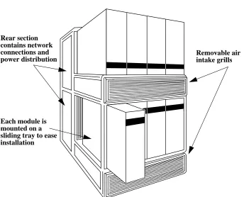
The CS-2 Bay is a tubular structure that forms a platform for the CS-2 modules. It includes the interconnect for the modules’ control and data networks, and the power distribution circuits.
The Bay includes the following features:
•
Modules are mounted on sliding trays to enable easy installation and removal.•
Power distribution box.•
Enclosed cable ducts for the data network cables.•
Service access panels to front and rear.•
Air channels to maximise flow of cooling air through the modules.2 S1002–10M143.01
1
Figure 1-1 A Single Bay
Each module is mounted on a sliding tray to ease installation Rear section contains network connections and
Service Access
2
The Bay includes service access panels at its front and rear.
You will need to remove the access panels when removing or installing modules. You may also need to remove the access panels when routing peripheral cables from a module; typically these cables will be routed from the front of a module to the rear of the Bay via the ducts beneath the module.
Front Panel (Air Grill) Removal
The lower (charcoal colored) grill covers the air intake and cable guide for the lower modules; the upper grill (purple colored) covers the air intake and cable guide for the upper row of modules, and also hides the baffles which route the warm air exhaust from the lower modules through to the rear of the Bay.
4 S1002–10M143.01
2
Rear Panel Removal
Two rear panels are fitted to the rear of each Bay. To remove a rear panel locate the two captive screws along its top edge and rotate each by a quarter turn. Pull the top edge of the panel away from the Bay and lift the bottom edge from its guide. Installation is the reverse of removal; ensure that the small holes along the bottom edge of the panel mate with the pins on the Bay.
Power Connections
3
The Bay has no power requirements itself but does include a power distribution circuit to provide power to the modules.
Each CS-2 Bay requires the following power connections:
•
EUR: 415V, 30Amp, 3 Phase (5 wire).•
US: 208V, 45Amp, 3 Phase (5 wire).Each CS-2 Bay is supplied with a 3-phase distribution panel and 3m detachable flying lead that is terminated by a 3 phase plug (pin style to IEC 309-1 and IEC 309-2):
•
EUR: series 1, 240–415V, 30Amp, 3 pole+Neutral+Earth•
US: series II, 120–208V, 60Amp, 4 pole-5 wire.6 S1002–10M143.01
Module Installation
4
Introduction
To ease installation and removal each module is located on a sliding tray.
Connection of the module to the CS-2 data network is via Beta Flex connectors fitted to the bay. Connection to the control network and power distribution is via cable connection to the module’s power supply. Additional connections from the module’s boards to external peripherals may be made from the front of the mod-ule to the rear of the Bay via cable ducts beneath the modmod-ule.
Removal and Installation Instructions
The following steps should be used to remove a module from the Bay. Reverse the procedure when installing a module.
Your attention is drawn to the illustrations at the end of this chapter.
1. Switch-off the module.
10 S1002–10M143.01
4
Figure 4-1 Skeletal Illustration of a Single Bay
Rear access panels Module extended on
its sliding tray
Air and cable ducts for upper modules
Air and cable ducts for lower modules
4
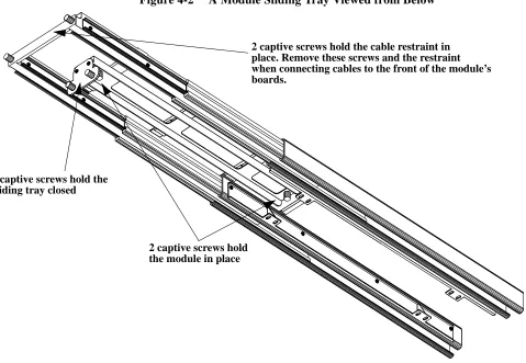
Figure 4-2 shows a module’s sliding tray when extended and viewed from its un-derside. It shows the two captive screws that are used to hold the module in place, and the two screws that hold the tray closed. Cables that are connected to the front of the module’s boards are routed behind the retaining bar and via cable ducts to the rear of the Bay.
Figure 4-2 A Module Sliding Tray Viewed from Below
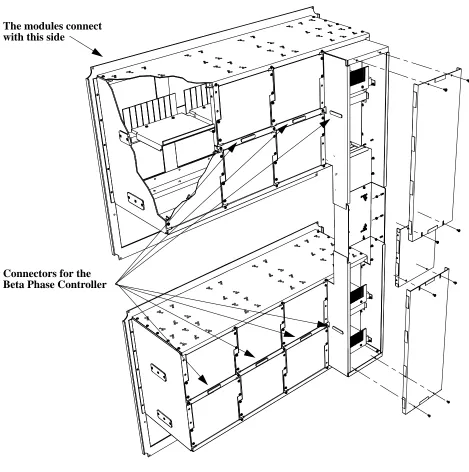
Figure 4-3 shows the backplane box for a Single Bay. This box encloses the
ca-2 captive screws hold the module in place 2 captive screws hold the
sliding tray closed
12 S1002–10M143.01
4
Figure 4-3 Backplane Box for a Single Bay System
4
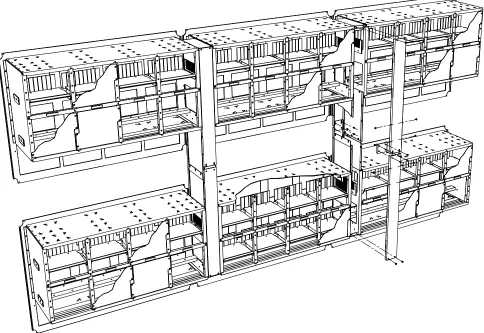
The backplane box for 1, 2, and 3 Bay systems are slightly different in configu-ration. Figure 4-4 shows the backplane box used for a 3 Bay system.
14 S1002–10M143.01

![[S263.Ebook] PDF Download .pdf](data:image/gif;base64,R0lGODlhAQABAIAAAP///wAAACH5BAEAAAAALAAAAAABAAEAAAICRAEAOw==)