Supporting
multi-modal and multi-medial user interfaces
from an embedded environment
Master Thesis G.J.M. Braam October 2006
Home Automation Europe
ir. A. Noorbergen
Human Media Interaction
prof. dr. ir. A. Nijholt dr. E.M.A.G. van Dijk dr. J. Zwiers
Date first created: 03-JAN-2006 Summary:
Last modified: 13-OCT-2006
Document number: HAE-200601-001
Document revision: 1.67
Author: JB
Classification: PRIVATE
This report describes my research, design and partial realization of a tech-nical framework to support multi-modal and multi-medial user interface clients from an embedded environment. This framework supports multi-ple in- and output modalities, multimulti-ple types of connection media, syn-chronization between different instances on different types of media and bi-directional communication with these user interface clients.
© Home Automation Europe BV. All rights reserved.
G.J.M. Braam - 2 - MM & MM UI
Abstract
This report describes my research, design and partial realization of a technical fra-mework to support multi-modal and multi-medial user interface clients from an em-bedded environment. This framework supports multiple in- and output modalities, multiple types of connection media, synchronization between different instances on different types of media and bi-directional communication with these user interface clients.
I show how these user interfaces will be operated by end users and by configuration users, the latter being more technical than the first. Each has a somewhat different set of demands from the user interface that they use, although in the end the ser-vices supporting both will be based on the same basic low-level primitives.
The base framework that I have designed to support these user interfaces provides low-level functionality like message routing, event notification and connection track-ing. As a part of this base I also specify a message protocol that can handle the com-munication requirements internally within such a framework as well as externally, with the user interface clients. By means of the message protocol and the driver model I have incorporated an abstraction level over the connected devices that en-ables them to be addressed and controlled in a uniform way, resulting in a high level of modularity.
At the time of writing I have completed the framework to a point where it delivers a reliable base for message delivery and driver stability. Other driver and user interface developers, who are also seen as users of the framework, can now do their work without needing to know all the low-level information about the other parts of the framework. I have developed prototype drivers and user interface clients for differ-ent platforms and hardware standards that connect with the framework, of which the client PocketPC Flash Application is the most feature rich.
G.J.M. Braam - 3 - MM & MM UI
Preface
My name is Jurgen Braam and this project is the final step in obtaining my masters degree in Computer Science with the cluster Human Media Interaction at the Uni-versity of Twente. The report you see before you is the result of the ten months I spent at Home Automation Europe in Amsterdam working on this project.
First I would like to thank Arjen Noorbergen and Joris Jonker for allowing me to do my final graduation project at Home Automation Europe and for allowing me my extremely flexible working hours, without which none of this would even have been possible.
I would also like to thank Anton, Betsy & Job of my graduation committee for their supervision and advice for the cluster Human Media Interaction at the University of Twente.
Further I would like to thank all my colleagues at Home Automation Europe that have made the office feel like a second home to me, both during and after office hours.
The following people deserve a special mention for our work together on various pieces of software: Hamid Godaei (Phone & A10/X10 driver), Hasan Hoztas (Zigbee driver), Do Jacobsson (PocketPC Lite Control), Leon Lanen (Phone & RFxcom driver) & Ar-jen Noorbergen (HCBhw driver).
And last but not least a muchas gracias you to everybody that has helped me by proof-reading my report countless times, you know who you are!
Jurgen Braam,
G.J.M. Braam - 4 - MM & MM UI
4.1.1. Compared to M4UI Layers...26
G.J.M. Braam - 6 - MM & MM UI
1. Introduction
Alice is at work, she just had a long meeting with her boss and now finally has time to take care of some personal things. She logs in to the web portal of her house via internet, it shows that nobody is at home. Be-cause it has been a pretty dry week she sets the garden sprinklers to go for one hour right after the sun has set. Furthermore she turns up the temperature because her daughter will be home from school a bit earlier than normal.
Peggy is digging in her bag to find her electronic key. When she finally retrieves it and opens the front door she thinks “Nice and warm inside, mom must have turned on the heater for me”. The lights automatically go on in the hallway, the living room and in her own room. The TV also turns on tuned to MTV, her fa-vorite channel for relaxing after school. Peggy uses the home remote to let down the sun screen outside a bit, because she can hardly see the TV image. In a moment of brightness she also uses it to turn off the lights in the hallway and in her room, knowing what her mom thinks about wasting energy. In her office, Alice smiles when she sees the SMS message sent to her phone right after her daughter has entered the house. Finally Alice gets home. Using her electronic key to enter, the lights are now coming on in the hallway, the master bedroom and the kitchen. She thinks “ah, the hallway light went on” and realizes that Peggy must have turned it off after she came home. After giving couch-potato Peggy a kiss: “we’re leaving in ten minutes dear,” she goes to her bedroom to change out of her work clothes. She hurries to get ready for the evening out with her daughter and husband, knowing that he is now wrapping up at work after he got an SMS telling him of her arrival at home. Downstairs Alice meets her daughter at the front door and sets the alarm. Automatically all lights and non-essential appliances in the house are turned off. A short while after the car has left the driveway, the porch light turns itself off as well.
1.1. User Interfaces
User interfaces (UIs) are all around us: some are apparent in the form of a computer screen, or the screen of a PDA. Others are less evident and embedded in the use of an object, like the use of an elec-tronic RFID key in the introduction story. Another example includes a form of embedded intelligence which in fact enables a larger user interface construct, like when all the lights go off as a result of the activation of the alarm.
For brevity, a Multi-modal and Multi-medial User Interface, or MM & MM UI, shall be abbreviated as
M4UI in the remainder of this document.
1.1.1. User Interface Focus
The user interfaces that the title of this document refers to are generally the kind that have use of a vis-ual display and a way of manipulating them. They can best be described as regular ‘remote controls’, like the one that controls a television, but with an LCD screen and the fact that some of the user interface elements are determined by the layout of the home it is controlling. More physical interactions like for instance flipping a switch mounted on a wall, or telephone-based voice menus are also considered to be among these UIs.
The multi-modal aspect refers to the fact that any combination of inputs can be received at any time. Commands can be received simultaneously from local physical devices, GUI clients, Interactive Voice Response (IVR) systems and from remote web portal control actions. Any number of these user inter-face instances could be operated at the same time. This introduces a need for minimal delays with re-spect to command execution and displaying the actual state of the home.
G.J.M. Braam - 7 - MM & MM UI
To finalize the explanation of the title of this document: the focus lies on the design of flexible software that runs in an embedded environment, while it provides support for the necessary features so these M4UIs can do their work properly.
1.1.2. Providing Support
The user interfaces discussed here are meant to control something: that also means that they need to communicate with some entity that will actually carry out the commands and can send information mes-sages back to the output part of the UI. Basically you need a supporting framework that can take care of all sorts of things like message generating, parsing and routing, as well as components that interpret messages, take actions and possibly send back messages so the UI can display the new situation if the state of the home has changed. These UIs, and especially the ones that display dynamic elements need a base to develop on top of.
We are looking at a base that needs to be able to run in an embedded environment. Embedded because we will want this support to be always available, so it should always be turned on, have a low power con-sumption and offer a high reliability. In embedded devices these features usually translate into a system that is severely limited with respect to processing and memory resources.
Generally these limitations can be lived with if you choose the operating system and implementation language wisely. The operating system should allow for sufficient development freedom and the lan-guage should be as low-level as humanly possible, to avoid unnecessary overhead. These needs can be satisfied by developing for a UNIX or linux environment and by using the ANSI C language. A nice bonus is the fact that this combination is very portable, so it can run on a wide variety of hardware and operating systems.
The Home Control Box platform, which is currently in development at Home Automation Europe, is an
excellent candidate for hosting such a support base framework.
1.2. Home Automation Europe
Home Automation Europe (HAE) is a young and dynamic company, active as systems integrator on the market for domotics and home automation. They design and deliver advanced solutions for control of home systems in larger projects that improve the comfort and safety of the inhabitants. Besides deliver-ing the necessary hardware for the projects and handldeliver-ing executive control of these projects, they also develop software and services in the area of home automation.
1.2.1. Home Control Box
To be a true systems integrator, HAE is developing the Home Control Box (HCB) platform: a dedicated embedded computer system that links various systems in a home. The HCB is equipped with embedded software that can create an intelligent home by devising smart scenarios that combine information from various systems that are normally not, or can not be inter-connected. This allows real life situations like described in the short introduction story to become a reality.
For the technologically-oriented, the specifications of the HCB include an ARM processor running at 73 megahertz, 64 megabytes of internal memory and 128 megabytes of flash disk storage space. The operat-ing system runnoperat-ing on this hardware platform is an embedded, lightweight version of linux. Currently there is one big monolithic program, implemented in the interpreted programming language Perl, that controls all of the connected hardware and delivers the user interface to a client. Only a configuration interface is available at this time, which can be reached by using a standard web browser. For more in-formation please see Appendix III ‘HCB Technical Specifications’.
The HCB needs a new supporting base framework that will replace the legacy Perl application. The be-fore-mentioned M4UI concepts have also been on the HCB wish list for a while. The combination of
these two factors leads HAE to start development on a new framework. It will be referred to as HCBv2
G.J.M. Braam - 8 - MM & MM UI
1.2.2. Technology Overview
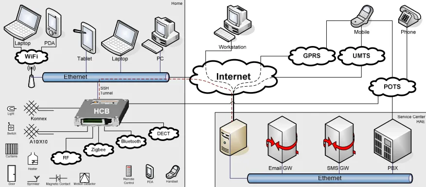
To give a quick glance of the possible devices and connection media that the HCB will interact with, both in- and outside the home, a schematic view is given here in Figure 1-a:
Figure 1-a. Connection Media and Devices in relation to the HCB
You can see the HCB as the central connection hub in the home on the left, with some of the services like SMS and E-mail connectivity delivered via the Service Center which is operated by HAE. An HCB installed in a home is usually connected to the Service Center via the internet. The devices at the bottom left are not specifically connected to one of the standardized media because the HCB unites them all and allows normally incompatible devices to now work together. A number of the connection media are still in early development stages, so commercial products are not yet available for some of them.
Konnex [KNX] and A10/X10 [X10] are examples of home automation standards that mainly use wires to transmit their commands, while Zigbee [ZIG] and Bluetooth [BLU] are general wireless standards. The HCB will be able to communicate with these devices using any of these standards and offer one uniform way to program and control them, by consistently making use of internal abstraction levels.
User appliances like PDAs, phones and different types of remote controls can be used to directly con-trol devices in your home. All of the lights in the house can for example be concon-trolled from a single PDA, or comfortably and securely from behind a computer at the company office. Some of these ac-tions can be scripted, like for example turning on the garden lights for fifteen minutes when somebody comes home at night.
1.3. Document Structure
1.3.1. Project Goals
G.J.M. Braam - 9 - MM & MM UI
1.3.2. Previous Work
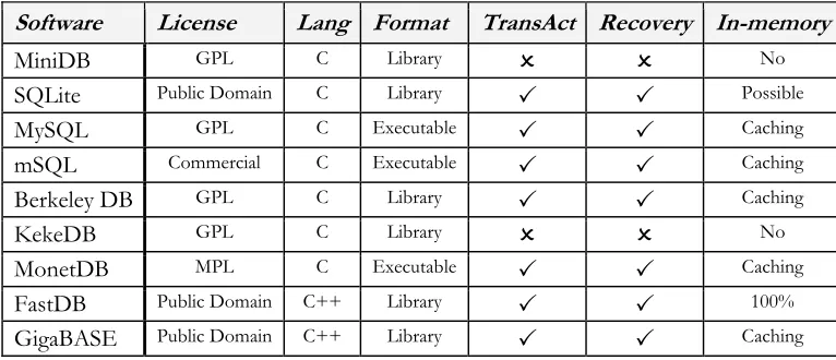
There has not been a lot of work done in the specific area of supporting multiple client interfaces from frameworks that can run in a severely resource-limited embedded environment. Most of the few solu-tions out there that are in any way relevant, need at least a desktop-class PC to run on, and certainly cannot function adequately in an embedded setting.
The first and most extensive of these is Mister House. Written in the interpreted programming language Perl, Mister House is a free open source framework that can control all devices in a home and can easily be extended with custom code. Everything in Mister House is done sequentially in a single main thread, which includes serving files from the embedded web server. With the proper interface hardware the framework has built-in support for X10 and can be controlled by for instance a web browser, e-mail, speech recognition, instant messaging, all sorts of serial devices and even a phone voice menu delivered via tellme.com. Regrettably this framework has become far too heavy to run in an embedded environ-ment.
The first prototype software for the HCB platform developed at HAE is based upon a very early version of the Mister House framework and has since been severely customized to suit the embedded needs of the HCB. The configuration interface, served by the embedded web server, allows the specification of custom scenarios via the built-in macro editor. It is possible to use conditions like device state changes, date, time, A10/X10 events, phone commands and user variables & timers. Actions that can be per-formed include device operation, A10/X10 commands, digital output port state changes, e-mail & SMS message sending and of course manipulation of user variables & timers. Execution also takes place in one sequential loop which, when using large numbers of macros, has been known to run with the unac-ceptable frequency of up to 5 seconds per iteration, or 0.2 Hz.
Please bear in mind that the features described above do not require strict real-time scheduling con-straints and that the HCB does not provide a Real-Time Operating System needed to guarantee such restraints.
1.3.3. Research Questions
Based on the descriptions given of M4UIs and the new HCB system to be developed, my work will
fo-cus on providing answers to the following question:
How should a flexible architecture that provides support for multi-modal and multi-medial user interface clients, while running in a severely resource-limited embedded environment be developed?
To guide the direction in which the work will progress and to make this task less abstract I have com-posed five derived questions:
Who will be the users of the system, and what will they expect from it?
How to set up a solid base framework to support the functionalities that the UIs will be needing?
What demands does this system have with respect to data communication to and from the UIs?
What type of protocol or protocols should be used to convey information?
How to incorporate maximum flexibility to support current and future technologies?
G.J.M. Braam - 10 - MM & MM UI
1.3.4. Approach
The outcome of the process of answering these questions is distributed over ten chapters, each of them relating to a different part of my work at Home Automation Europe. A short description of each is given here:
Chapter 1. Introduction
The introduction describes the user interfaces and their support in both generic terms and in relation to the new HCBv2 reference framework. It also projects the research direction and the structure of the document you are presently reading.
Chapter 2. Orientation
The design overview provides an aggregation of the entities and the requirements relating to M4UI
frameworks. It starts with an inventory of the features that a generic M4UI framework will need to
provide. Then it proceeds with a list of the features that are required for the HCBv2 framework, on top of those already given for a generic M4UI framework.
Chapter 3. M4UI Structure Design
A generic architecture layout for supporting M4UIs from a communications standpoint is given in
this chapter. It illustrates the four layers it can be broken down into, with a short description of each.
Chapter 4. HCBv2 Framework Design
We then continue with a more detailed specification of HCBv2 with its different components and their interconnectivity. This chapter gives a broad view of all the components involved in the HCBv2 Core system.
Chapter 5. BoxTalk Protocol
The protocol that will be used for internal and external communication is presented here. This chap-ter will start with the required features, then list relevant existing protocols, review each and finally present the selected solution. It closes with a specification of the types of messages.
Chapter 6. Preparation
This chapter details my initial preparations and the wide range of supporting practical facilities that I have set up to ease the implementation process for developers.
Chapter 7. Implementation
The realization of the HCBv2 reference framework to where it can support M4UIs and subsequently
the UIs that I built to run on it, are described. It also gives an overview of the different binaries that have or will be created as a part of the framework.
Chapter 8. Conclusions
In conclusions the state of the framework that is implemented at this point in time is tested against the M4UI and HCBv2 requirements. The research questions given in the introduction will be
an-swered and the different parts of the framework and the UIs will be evaluated.
Chapter 9. Epilogue
G.J.M. Braam - 11 - MM & MM UI
2. Orientation
In this chapter I will assemble the information needed to make a well-formed design for the Generic M4UI Structure and the HCBv2 Framework given in chapters 3 and 4 respectively. Before we can
pro-ceed with composing requirements, we first need to look at the different types of users that will be working with the framework and attend to the various types of clients that can connect to a base framework. The reason for this is because the user and client types each have a different set of features that they require. Finally we will discuss two groups of modalities in relation to interaction patterns with UIs.
The requirements are then gathered into two sections: the requirements for generic M4UI systems and the
requirements specific to the HCBv2 framework used for actual development. These requirements are as-sembled from a number of sources. Most of them are harvested from studying the generic features of the old Perl HCB prototype application, or extrapolations of generic features clearly missing from it. These features, or lack thereof, have generally taken shape in discussions together with colleagues at HAE as a result of software testing or practical experiences with the old configuration interface. Per-sonal experience with UIs and market movements with respect to media-rich devices contributed as well.
→ Please note that all the requirements for M4UI systems are automatically also necessary for the
HCBv2 framework.
2.1. User Types
The features that will be described in the two main requirements sections will be used by four groups of users. They provide an answer to one of the research questions: “Who will be the users of the system, and what will they expect from it?”
Driver Developer
The driver developer is the person that will be working with the facilities that the framework pro-vides, in order to develop new low-level features for the framework that can be accessed with high-level methods. In the case of HCBv2 this will be a technically oriented software developer that will add support for a specific hardware technology to the HCB, allowing the other parts of the frame-work to frame-work with these devices right away through an extra abstraction level. These users will want to be able to write their drivers focusing on the hardware they are supporting, without having to cre-ate too much overhead code or deal with complex APIs.
User Interface Developer
The framework will be equipped to handle UIs that run on a wide variety of different platforms. It is therefore very likely that the UIs that will run on the framework will be designed by developers with an equivalently wide variety of design backgrounds. Those developers are predominantly creative people that on average have less low-level technical knowledge. They will be working in their own familiar environment and creating UIs that need an internal protocol for exchanging messages with the framework. The UI developers will want this protocol to be both easy to work with and flexible enough to support all the features they need for their UIs to function properly.
Operational User
G.J.M. Braam - 12 - MM & MM UI
Configuration User
For HCBv2the configuration user makes use of more complex UI elements that enables the person to adjust what devices are connected and configure the specific properties of each. The actions that the configuration user takes can, among other things, influence the number or grouping of elements that the end user sees on a specific UI screen. Less technically oriented configuration users would like to be able to adjust the configuration to their needs without help or training. More advanced users will want to change all of the possible settings and get the maximum in customizability and flexibility out of it. Also the configuration users, who are often installation engineers with a mainly electrical background, want to be able to configure devices without knowledge about how they will be repre-sented in the various user interfaces or how they need to be addressed and controlled.
→ Note that in the case of the M4UIs there is no semantic difference between the configuration user
and the end user: they are both simply entities that operate a UI.
2.2. Client Types
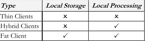
Client types are regularly divided into three categories [CLI]. Table 1 gives a quick over-view of the types and their characteristics.
Table 1. Client Type Characteristics
Fat Client
A fat client, also known as a thick client or rich client, is a client that performs the bulk of any data processing operations itself, but does not necessarily rely on a server. The fat client is most common in the form of a Personal Computer, as the PC can operate independently.
Thin Client
A thin client is a minimal client. Thin clients use as few resources on the host device as possible. A thin client's job is generally just to graphically display information provided by an application server, which performs the bulk of any required data processing.
Hybrid Client
A hybrid client is a mixture of the above. Similar to fat client, it is processing locally, but rely on the server for the storage. This approach offers features from both the fat client (multimedia support, high performance) and the thin client (high manageability, flexibility).
For the M4UI and HCBv2 architectures most of the clients will be of the hybrid type since all
informa-tion will constantly be communicated to and from the server from all connected clients, while at the same time they will use the locally available processing power to enhance interaction speed and mini-mize the load on the architecture.
Next is a list of the prospective clients for the HCBv2 architecture and their characteristics. All of these clients are of the hybrid type, with the exception of the hardware peripherals, which are of the thin type.
JavaScript Application
This client will mainly be used as the HCB Configuration application for Web Browsers. This applica-tion will eventually replace the current Perl Configuraapplica-tion Interface, of which a screenshot can be seen in Figure 4-b. It will consist of a set of scripts that will be started from a single HTML page and then run as a full-fledged client-side application. It is a client that is going to be a part of the standard HCB package and for which development will probably not start within the scope of this graduation project.
Type Local Storage Local Processing
Thin Clients
Hybrid Clients
G.J.M. Braam - 13 - MM & MM UI
Figure 2-b. Xanura DAIX10 It is however not unlikely that small, highly specific
Java-Script control applets will be developed to be used as a part of the portal site that will run on the Service Center.
Flash Application
For web-developers Macromedia Flash has become the standard for dynamic, graphically pleasing user interfaces and web pages. A lot of people are schooled in its use and it em-ploys a powerful embedded scripting language called Action-Script. Flash has excellent support for vector-based graphics and thus perfect for scaling to non-standard resolutions found on phones and PDAs. To the right in Figure 2-a is a screenshot of a demonstration interface developed at HAE as a result of an internship.
Java Application
Java is a well-known language under developers and most software developers have worked with it at some point during their career. It has powerful network capabilities and comes in many flavors. As part of the Java Platform, Micro Edition (J2ME), the Mobile Information Device Profile (MIDP) is an API that is supported by most of the modern phones and PDAs on the market today. It offers functionality used in LCD User Interfaces and basic 2D gaming, perfect for developing a user-friendly and graphically pleasing interface. Programs written as MIDP MIDIlets can execute directly on many phones and PDAs.
Care should be taken that the user interface is useable on a wide range of different screen resolutions. MIDP includes API for communication with all the hardware that is present on the device it is exe-cuting on. Possible connection media thus include Infrared, Bluetooth, Wi-Fi, GPRS, UMTS, SMS and Email.
Native Application
Software that executes natively on PDAs, SmartPhones and more complex remotes with a graphical user interface might be needed to support certain platforms. Development of this form of non-standard software will be avoided if possible, but if demand is high enough for a certain type of de-vice, it might be worth the investment. Both C and C++ offer fast and efficient code execution and, depending on the platform, powerful network facilities.
A lot of the internal code can be shared with applications to be developed for other platforms that fall under this category, which will make it easier to develop similar clients after the first one has paved the proverbial road.
Hardware Peripherals
These clients will have minimal or no application and display logic. The largest part of the devices that connect to the HCB fall under this category and will be commercially available home automation components. They all support at least a one-way communication channel to the HCB, either as command provider or as a information receiver. An example of the first is a simple light switch that sends an event, an example of the second is a remote controlled lamp that can receive a command to turn itself on or off. These clients usually do not have a screen, some have a simple state that is visible, like a light that is on or off, or maybe a LED indicating that it is active.
An example of such a device can be seen in Figure 2-b. It is a Xanura DAIX10 dim actor and inter-face module which can be built into a wall socket. It can send commands from a physical dimmer and at the same time output a voltage according to dimming commands it receives.
Some of these clients and their development will be discussed further in §7.4 ‘User Interfaces’.
G.J.M. Braam - 14 - MM & MM UI
2.3. Modalities
The concept of Multi-modality can be divided into two groups: ‘Sequential Multi-modality’ versus ‘Si-multaneous Multi-modality’ [RIN]. This division has impact on the complexity of the user’s utterances and they way that they are inter-connected.
In the sequential one a system that supports multi-modal input is restricted by some form of progress script that determines at what point in a user interaction exchange a certain modality is allowed. Imagine a phone call to a technical support helpdesk (maybe that of Packard Bell) in which you are first required to enter the serial number of the troublesome device in question by means of the number keys on your phone. Next, in order to verify your current address which is read aloud by a text-to-speech voice syn-thesis application, you need to speak either the word ‘Yes’ or ‘No’. After that you can navigate though an Interactive Voice Response system by means of your number keys again, and finally go make some tea while you wait for an actual helpdesk representative to talk to you. One input modality interaction is clearly scheduled after the other, and no overlap or interaction between them takes place.
The simultaneous one would be a system that allows free-form interaction by means of multiple input modalities in a non-determined order. An example of this case could be a fictive interactive digital city guide mounted inside a small booth located on one of the many the prominent city squares. This system asks what we are looking for and we say that “we want to go to a museum”. It shows the map, centered around the you-are-here marker with the nearest museums highlighted on it. While you tap on the screen to select a museum you ask “how much does this one cost for two people?” It replies with a price and the suggestion to make a reservation, because there is currently a long waiting line. You then say “please reserve place for two people at four o’clock” and insert your credit card. These input modalities are used at random times and can signify all kinds of decisions in the current session. The utterances in the different modalities need to be used together in order to understand what the command really is, a process also known as semantic fusion. This kind of interaction is much more complex to support, es-pecially if the environment is susceptible to noise or other non-intended inputs.
The M4UIs handled here are mostly sequentially multi-modal, by reasons of processing complexity. An
embedded platform such as the HCB does not (yet) have the power to handle these complex interaction patterns, let alone be able to perform tasks like real-time speech recognition.
Recent market movements towards using more complex modalities in daily-use appliances, of which TomTom is the primary example for audio, are paving the road for other appliances with these modali-ties. Devices with hardware support for these capabilities built into them will probably be appearing in the near future, so support for these more complex modalities should certainly be taken into account.
2.4. M
4UI Requirements
Given here are a set of general requirements for home control user interfaces that are multi-modal and multi-medial, as well as those for the underlying facilities the UIs need to perform their duties. The re-quirements that relate to the internal workings of the clients and the way that the architecture supports them are listed in the paragraph Data Transfer. Subsequently, requirements that pertain to the part that users will interact with are given in the paragraph User Interface.
→ In the following paragraphs the supporting base framework and specifically the part or parts that will be responsible for handling connections with clients will simply be referred to as ‘server’.
2.4.1. Data Transfer
The requirements listed here relate to data that is transferred to or from UIs. These requirements will help when designing the lower-level communication support services, the structure of the information that will be transported and be used for guidance during the implementation phase.
Message Sending
G.J.M. Braam - 15 - MM & MM UI
Message Receiving by Server Push
For receiving messages there must be a minimal delay from the time that the event occurs on the server to the time that it is received by a client. This means that polling is not an option and a form of server push probably needs to be used.
Reliable Message Delivery
Messages that are sent either to or from the client need to be reliable. It must not be possible for a message to get lost during regular communication.
Long-time Connections
Some of these clients can be connected and remain idle for very long times. Issues like visible time-outs and the subsequent need to (manually) reconnect should be avoided. A good maximum is probably 120 hours, or five days, as is the specified period for established TCP/IP connections to stay connected without any data transfer.
Location Independence
Clients need to be able to connect from virtually anywhere in the world. This usually makes one think about internet-based solutions, but message carriers like SMS and GSM modems could also apply here.
Connection Medium Independence
Connections to clients should not be dependent on the connection medium they are sent over. This will enable the use of connection handovers in the future, for instance automatic switching from GRPS to the local WLAN when you get home from work without losing client connection and state information.
Authentication & Authorization
Clients need to authenticate themselves to ascertain their identity on the server. Further some sort of a permissions or role system is needed to authorize recognized users before they can perform certain actions.
2.4.2. User Interface
The requirements shown here pertain to the client-side aspects of graphical UIs that perform a control task over one or more parts of a home.
Intuitive & Easy to Use
The UI running on the clients for daily use needs to be intuitive and it should be possible to start us-ing them with minimal or no help.
Consistent Look
A consistent look needs to be maintained over the different screens within clients, as well as over the different clients on different platforms. This will ensure that once a user can use one of the clients, they can use all of them and generally leads to a more pleasant user experience.
Fast Interaction Response
During use of the interface the operations performed by the user must show that some action is be-ing taken by the client right away. This action may not depend on communication with the server first, since in some cases this could take too long. The actual command and confirmation delay, being a round-trip time, should be below two seconds to be usable from the user’s perspective.
Transparent Internal State
G.J.M. Braam - 16 - MM & MM UI
Dynamic Element Support
Support needs to be present for dynamic UI elements, of which the contents are supplied by mes-sages. This includes adding and removing of elements at run-time.
Element State Updates
Upon reception of a message with a new state for a control element, the visual state of that UI ele-ment must be updated to show this new state.
Multi-media Elements
The UIs will have to be graphically pleasing with smart placement of text, images and possibly small audio effects to attract attention to events. In the future it could also be possible to send icons and other multi-media data to the clients for use as part of the UI.
Useable on Touch Screens
It is necessary that the interfaces work with touch screens and also with regular screens that do not offer this modality. User interfaces with touch screens are preferred however, since they are the ones that are the fastest and easiest to use.
Useable on Multiple Resolutions
There are a lot of different small resolutions used on PDAs & phones. The UIs need to be useable and the text readable on all but the tiniest screens.
Complex Modalities
Support for the more standard modalities like keyboards, mice, buttons & touch screens for input and screens & audio for output are nothing special nowadays. Supporting the more complex modali-ties like speech recognition or gesture recognition will be important assets in the future.
These requirements will play a supporting role during the actual design of the UIs themselves, but some also rely on communication features given in the last Data Transfer paragraph like for instance sending multi-media content to be used as a UI elements for display or playback.
2.5. HCBv2 Requirements
Using the requirements for M4UI as a basis, this section lists the requirements specific to HCBv2, the
new framework for the HCB hardware platform. All the requirements listed in the previous section automatically apply to HCBv2, with a number of specific UI-related extensions given in the paragraph
User Interface.
The requirements regarding the other underlying features needed in the HCBv2 framework are de-scribed in the next paragraph, Functionality. The HCB will especially be interfacing with a large variety of
Hardware, essentially the reason for its existence. The hardware part is divided into paragraphs on
Connec-tion Media and on Devices.
2.5.1. User Interface
On top of the requirements specified for Generic M4UIs which also apply here, these add extra features
that are only relevant to UIs used in combination with the HCB and its specific applications.
User Complexity Levels
G.J.M. Braam - 17 - MM & MM UI
Sensor Device Support
The UI needs to be able to display values for devices that do not have a control aspect associated with them. In contrast to the controls that are needed for switching and dimming devices, these sen-sor device UI components only display a certain value like for instance a temperature or the value of a custom user variable.
Device Categorization
The UI needsto be able to display devices in categories. Categorization can for instance be on the room, location or group that the device is in. Navigating between these categories needs to be fast & easy.
Large Numbers of Categories/Devices
There must not be a certain maximum of categories or devices per category that can be displayed be-cause of for instance lack of screen real estate. The UI needs to be built to handle theoretically unlim-ited number of categories/devices, although I imagine scrolling through hundreds of categories could get tiresome after a while.
Estimated Processing Times
Using estimated reaction times to display UI component “Processing…” states while sending a command over a known non-instantaneous connection medium could significantly improve the user experience. These time estimates could be sent along with the Home Layout message described under Message Protocol in the next paragraph. For instance, sending messages over X10 can take up to a full second to complete.
2.5.2. Functional
In this paragraph the general features required and used by practically all parts of HCBv2 are enumer-ated. Most of these features will probably be implemented in a shared library.
A complete list of these functional requirements is given here because at the time that these require-ments are being composed these features do not yet exist. Because the functionality that relates to user interfaces depends heavily on most of these features, their basic behavior needs to be explained here.
Data Storage
A place is needed where volatile and persistent data on the current state and configuration of the HCB is stored. A lot of this data needs to be accessed from multiple applications and processes that will be running on the HCB. Access to this functionality needs to be easy, robust, fast and as flexible as possible because this is an elemental component of the HCB Core structure that will be used fre-quently. Data like configuration settings, device states and macro definitions will be stored here.
Integrated Language Translation
Not all people that will be using the HCB will understand English at a sufficient level to perform ba-sic tasks. Support needs to be present to switch between multiple languages on the fly based on user preferences. This support needs to be tightly integrated into the system functions so a maximum of translation details are handled by the framework. The aim is to set up a system so that translation and parameter insertion (á la printf()) and basic mutations like uppercasing and lowercasing are handled automatically.
Dynamic Scripting
G.J.M. Braam - 18 - MM & MM UI
Central Logging
Developers will need a central facility to log messages about the configuration and use of the HCB. Because of the limited nature of the embedded platform care should also be taken to make sure that the available disk resources are used efficiently. Logging will be in a number of main categories, have a certain priority, be cached to minimize writes to the slow flash file system and be reliably transferred to the Service Center for processing & space preservation. The API will include functions with printf()-like arguments to facilitate parameter insertion in the log strings.
Security
Simple basic security features will be implemented in the first software version, full AAA (Authenti-cation, Authorization, Accounting) will be implemented in later versions. All local access to the HCB via LAN and WLAN are assumed to be safe: it is the responsibility of the end-user to secure their lo-cal network. External access from the internet is always routed through the Service Center so security can therefore be handled there. Care should be taken to allow for possible future 3rd party modules to be running on the platform with restricted rights.
Asynchronous Event Handling
The initial Perl implementation uses a synchronous polling model to check for new events and sce-narios. The new model needs to be event-driven and flexible enough to support communication of configuration settings, commands sent from/to devices and status updates sent to clients. Some sort of subscription system is needed to internally keep track of connected devices and clients.
Message Protocol
To communicate all commands and logistic messages inside and outside the HCB a separate message protocol is needed. All of the features listed in §2.4.1 ‘Data Transfer’ apply to this protocol. It needs to be set up so it can also service all the types of internal and external UI clients in a transparent and uniform way. The functionality as described will be used for local and remote connections with the HCB so the protocol to be designed should be flexible and efficient with respect to usage, speed and bandwidth.
To be clear about when we refer to this protocol it has been dubbed BoxTalk without having a com-plete specification at this time. The following types of messages have been identified:
General Device/Service Discovery
Devices, as well as the services provided by them, need to be announced to the system when they become available. Conversely a message is needed to announce the removal of a device and/or its services.
General State Variable Subscribe/unsubscribe
The possibility to subscribe to specific state variables, thereby receiving asynchronous updates when changes to this state variable occur. A way to unsubscribe is subsequently also needed.
General State Variable Updates
The state variables to which a client is subscribed need a way to be communicated. The device de-livering the service can send these messages to its subscribers to let them know a variable has changed.
General Action Request/Response
The ability todo some sort of remote function call by sending a request accompanied by possible parameters. The response is always received asynchronously to minimize pieces of the code that are blocked while waiting for a response.
Dynamic Room / Device Layout
G.J.M. Braam - 19 - MM & MM UI
Synchronized (Device) States
The interfaces on all clients would incorporate near-real-time synchronized, possibly multi-dimensional states on all modalities for all devices. The Subscriptions and Variable Updates can fill this need.
Device Commands
The ability to send specific commands to a unique device or to a group of them is needed. This can be achieved by using Action Request messages. A command can carry possible arguments, which is supported by the Action Request message above.
Connection Media and Device Response Times
The response times for used connection media and for specific devices should be communicated to clients for appropriate use of sync-delay and the use of sending/busy UI elements. Even some of the wired connection media, like for instance A10/X10, can take up to one second for a com-mand to be transferred. This information could possibly be sent as extra data with a Home Layout message.
2.5.3. Hardware
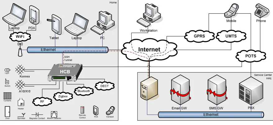
The hardware requirements consist of an inventory of existing and near-future technologies that the HCB could and most likely will work with. Support for the different technologies will be added incre-mentally, depending on the development roadmap, general standards acceptation and hardware device availability. Directly below in Figure 2-c is a copy of the diagram as shown in the introduction. It shows how the different devices connect to the HCB using the different media.
Figure 2-c. Connection Media and Devices in relation to the HCB
→ Please note the figure is repeated here to avoid unnecessary page flipping.
G.J.M. Braam - 20 - MM & MM UI
2.5.3.1.
Connection Media
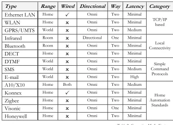
The different connection media are grouped in a number of categories:
TCP/IP-based (Ethernet LAN, WLAN, GPRS/UMTS) Local Connectivity (Infrared, Bluetooth, DECT) Simple Command Protocols (DTMF, SMS, Email)
Home Automation Standards (A10/X10, Konnex, Zigbee, Visonic, Honeywell)
In the future support might be added for connection media handovers. This would for example enable some clients to automatically switch from GRPS to the local WLAN when they get home from work without losing connection and state information. This means that a number of measures need to be taken when designing the communication protocol, sessions and with respect to client addressing and tracking. Also note that not all of the listed media are suitable for this kind of handover.
An overview of the evaluated media is given in Table 2 ‘Connection Media Features’:
Type Range Wired Directional Way Latency Category
Ethernet LAN Home
Omni Two Minimal
WLAN Home
Omni Two Minimal
GPRS/UMTS World
Omni Two Medium
TCP/IP based
Infrared Room
Directional One Minimal
Bluetooth Room
Omni Two Minimal
DECT Home
Omni Two Minimal
Local Connectivity
DTMF World
Omni Two Minimal
SMS World
Omni Two Medium
E-mail World
Omni Two High
Simple Command
Protocols
A10/X10 Home Both Omni Two Medium
Konnex Home
Omni Two Minimal
Zigbee Home
Omni Two Minimal
Visonic Home
Omni One Minimal
Honeywell Home
Omni Two Minimal
Home Automation
Standards
Table 2. Connection Media Features
G.J.M. Braam - 21 - MM & MM UI
2.5.3.2.
Devices
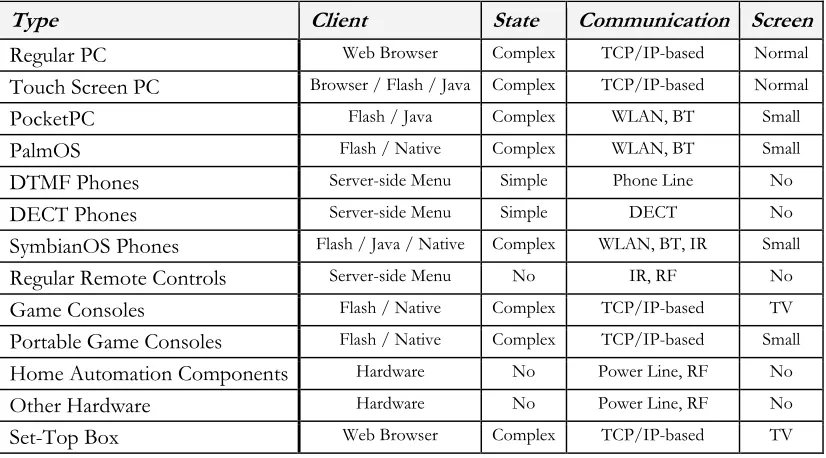
The word devices is taken very general here. Under devices I will assume all types of hard- and software that have some sort of user interface and can send and/or receive information when connected to the HCB. Bear in mind this is just an inventory of possible devices that could be used with the HCB, it is not meant to be complete or exhaustive. A quick overview of the discussed devices is given in Table 3.
Type Client State Communication Screen
Regular PC Web Browser Complex TCP/IP-based Normal
Touch Screen PC Browser / Flash / Java Complex TCP/IP-based Normal
PocketPC Flash / Java Complex WLAN, BT Small
PalmOS Flash / Native Complex WLAN, BT Small
DTMF Phones Server-side Menu Simple Phone Line No
DECT Phones Server-side Menu Simple DECT No
SymbianOS Phones Flash / Java / Native Complex WLAN, BT, IR Small
Regular Remote Controls Server-side Menu No IR, RF No
Game Consoles Flash / Native Complex TCP/IP-based TV
Portable Game Consoles Flash / Native Complex TCP/IP-based Small Home Automation Components Hardware No Power Line, RF No
Other Hardware Hardware No Power Line, RF No
Set-Top Box Web Browser Complex TCP/IP-based TV
Table 3. Device Features
Again, the complete and unabbreviated list is discussed in further detail in Appendix IV ‘HCB Hardware Requirements’ under the heading ‘Devices’.
2.6. Summary
The design overview given in this chapter reviews aspects like user types, client types and modalities, all of which are relevant to the composition of the requirements. Describing the user types also provides an answers to the research question about the types of users of the system and their specific needs.
The requirements listed for the M4UI and HCBv2 architectures provide a good reference when
compos-ing the design specifications and help to keep developers focused on important features durcompos-ing evalua-tion of possible open source soluevalua-tions and the implementaevalua-tion phase of custom software.
The description of home automation specific hardware in the form of connection media and devices supplies the reader with a general idea of these technologies and makes understanding the references to them from the rest of this document a lot easier. It also helps paint a picture of the environment that the HCB, as a universal systems integration tool, is operating in.
G.J.M. Braam - 22 - MM & MM UI
3. M
4UI Structure Design
This chapter presents a layout for a generic structure for M4UIs, in which an overview of the most basic
components needed in a M4UI client-server architecture is given. It also provides information towards
answering the “What demands does this system have with respect to data communication to and from the UIs?” question. Discussing this here provides an opportunity to only look at the M4UI-related
fea-tures and communication properties of such a framework, without being distracted by the numerous other details and features that frameworks of this kind are justly equipped with.
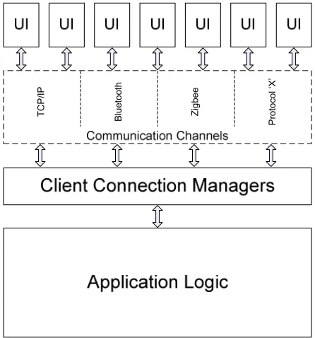
A generic structure for building frameworks to sup-port M4UIs can be broken down into four major
lay-ers, as shown in Figure 3-a:
In short, the UI clients, all very different devices with different communication capabilities, want to be able to exchange information with the Application Logic layer. Because of the diversity in communication channels, separate Client Connection Managers are created, one for each type of connection medium. They maintain the connections with the UI clients, relaying and translating messages back and forth, while they themselves are all directly connected to the Application Logic Layer.
→ Because of their limitations, the home automation standards X10 and Konnex are frequently being used as an example in the next paragraphs. This however does not mean that the following is only applicable to the field of home automation.
The four layers are described next, from the top down.
3.1. User Interface Clients
The UI clients range from regular web browsers to PDAs to light switches mounted on a wall. Any de-vice that has some form of output to show a user a state change (actor) or any dede-vice that can accept some form of input (sensor) can be a UI client. These devices would of course be in some way con-nected to a central system and be able to send messages, receive messages, or both.
Technically, a UI consists of a device with both in- and output capabilities, but for the sake of simplicity we will also refer to devices with only one of these capabilities as UI clients. Sometimes a combination of these devices form a bigger composite UI, like in the case where you flip a wall-mounted switch (sen-sor), some internal communication takes place, and a light goes on (actor).
These clients can support various in- and output modalities. We are especially interested in UIs that have a graphical way to display their state, like on a pixel-based screen, since they can convey a much more complex state to a user than for instance a single LED can. Some of these clients also support other out-put modalities like audio or vibration.
Input modalities include physical operation (like flipping a switch or turning a dimmer dial), device but-tons, mini joysticks, mice, keyboards and of course touch screens, which are most preferred, especially in combination with a small screen. More complex input modalities also include technologies like speech recognition and computer vision, but they are currently not yet relevant in embedded environments be-cause of processing power limitations.
G.J.M. Braam - 23 - MM & MM UI
The more advanced graphical UIs, the ones that run on PDAs for instance, can have dynamic parts of their visual interface structure for which the contents are sent over from the central system during run-time.
The connection media over which communication with the central system takes place is discussed next.
3.2. Communication Channels
An example set of interesting communication channels is given in §2.5.3.1 ‘Connection Media’. New connection media are being developed on a regular basis, some of which even become the ruling stan-dard for a period of time. This fact obligates serious frameworks that want to connect to multiple UI clients over multiple types of connection media to be designed in a modular fashion. This modularity ensures that support for new technology can be added to such an existing framework with relative ease. Some of these communication standards are general purpose, like for instance TCP/IP. They are sup-ported by standard components that are built into the hardware platform that the central system is run-ning on, like an ethernet port. Other communication channels are highly specific and usually a lot sim-pler, like the home automation standards X10 and Konnex. They require specific additional hardware in order to communicate.
Another point of interest is the one whether the protocols can transport arbitrary data messages, or only highly specific commands or events. TCP/IP and Bluetooth can for example transport any data, while X10, Visonic, Konnex et al. can only transport very specific commands. Then there are situations in which events from outside the UI-server environment can influence UI clients on the inside. An exam-ple: An unknown external X10 switch is programmed to emit commands for a device configured at a certain hardware address. If the device that belongs to this address is inside our network, then there will be interference and eventually disruption between the two expected behavior patterns.
These differences have far-reaching consequences in the implementation of the accompanying Client Connection Managers handled in the next paragraph.
3.3. Client Connection Managers
A Client Connection Manager is a software process that usually interfaces with connected communica-tion hardware in order to be able to use a specific conneccommunica-tion medium. This process handles communi-cation with all UI client devices that are connected via this medium.
Depending on whether this connection medium can transfer arbitrary data, it can either simply relay the high-level message from the Application Logic directly to the device, or it has to interpret the message and send low-level commands to one or more devices, while at the same time emulating the effect that these commands will have on the attached “medium universe”. It is possible that some commands are not even supported in the low-level protocol and that they need to be emulated with other commands or maybe even simply ignored. Of course, the same goes for messages that travel in the other direction. Having a modular solution makes solving these problems a lot easier and also protects problems in one from creating new problems in other modules.
3.4. Application Logic
This is the layer in which the actual application or business logic resides. The software that is in the ap-plication logic layer can consist of multiple binaries and processes. Generally only dependencies exist from the Application Layer on other lower level support services and not the other way around.
G.J.M. Braam - 24 - MM & MM UI
The Application Logic needs to contain a central entity that keeps track of all of the connected UI cli-ents and which Client Connection Manager or Managers currently have an active connection to those UI clients. The state, be it client-side or server-side, should not rely on data stored at the Connection Managers, so multiple connections, and with it connection handovers, are made possible.
3.5. Summary
This chapter has shown that a clear separation is possible between the parts of a framework that directly communicate with connected UI clients and the parts that are responsible for the Application Logic. A modular design for these Client Connection Managers will make the addition of support for selective current and future communication technologies relatively easy. The problems and complexity associated with a certain connection medium are nicely encapsulated within its own module.
After a clear view of the communication aspects of a generic M4UI framework, we can now look at the
G.J.M. Braam - 25 - MM & MM UI
4. HCBv2 Framework Design
This chapter defines in detail the new Home Control Box v2 framework that is to be implemented. It will illuminate all the separate facets of the framework and how they work together in order to answer the following: “How to set up a solid base framework to support the functionalities that the UIs will be needing?” Along the way it will show a number of investigations into choices for open source solutions that will be integrated into the framework. The chapter is divided into three main sections:
In the fist section the demands as specified in the requirements have lead to the definition of a coherent group of Components that form the main framework structure. They will form the basis for the different processes that will execute on the HCB. Also shown is the inter-connectivity of the components, which is achieved by means of libraries and communication.
The second section consists of the definition of a set of supportive dynamic Libraries tailored to specific tasks that will be used by the components and the other libraries. The information in these first two sec-tions combined will produce a good overview of the emerging HCBv2 architecture.
The next and final section details about the various Communication aspects in relation to the before-men-tioned internal BoxTalk protocol and in relation to the driver model. Special attention is paid to an in-depth explanation of the inner workings of a driver and what part the related libraries play.
4.1. Components
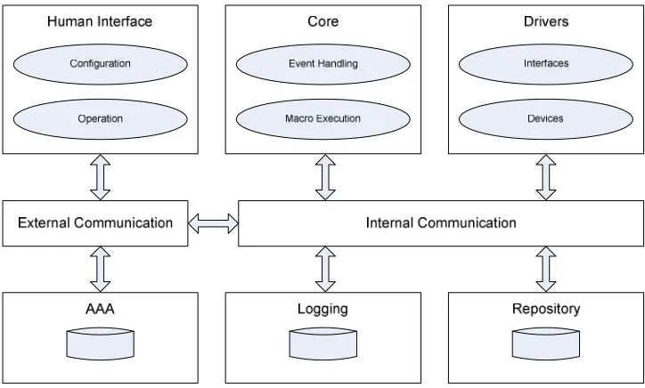
For a good overview of the architecture, Figure 4-a depicted below divides the high-level functional needs into several component groups:
Figure 4-a. Basic System Architecture for the HCB Components
The three top components groups Human Interface, Core and Drivers form the basic application struc-ture. This is where the application logic resides and this will be the most extensive part of the system. The idea of a Driver, a separate component that addresses a specific kind of hardware or technology, is part of the answer to “How to incorporate maximum flexibility to support current and future technolo-gies?”
G.J.M. Braam - 26 - MM & MM UI
All components communicate through the Internal and External communication components by means of BoxTalk messages. Each component sets up a separate connection with a central communication process, as will be described further down in section 4.3.2 ‘Communication Controller’.
4.1.1. Compared to M4UI Layers
→ To increase the readability of this paragraph, the many references to entities in previous paragraphs are shown in italics, a custom that is not repeated in the rest of this document.
When compared to the generic M4UI structure given in chapter 3, we can classify the relevant
compo-nents here into the layers described there. For the Human Interface group these are clearly equivalent to
the UI Clients in the top-most level.
The Core is of course the main place where the Application Logic resides, although some of this logic is also placed in the Human Interface and Driver components. The Configuration & Application clients and the
Drivers certainly do contain considerate amounts of logic specific to the application domain.
The Drivers are evidently analogous to the Client Connection Managers, although the concept of a Driver
de-scribed in more detail later on is much wider than just software that controls hardware for communica-tion purposes. Purely based on Figure 4-a however, a Driver and a Client Connection Manager are a perfect match.
The External Communication group here should in fact also include the Connection Media that the drivers
interface with, only then is it fully enclosed by the Communication Channels from chapter 3. Also, in this sense Drivers are actually connected to both Internal and External Communication channels: internal for BoxTalk message exchange, external for communication by using their own specific protocols.
4.1.2. Human Interface
The component group Human Interface contains the components that directly interact with the users. These UI clients can be divided into two groups: those used for Configuration and the ones used for Op-eration.
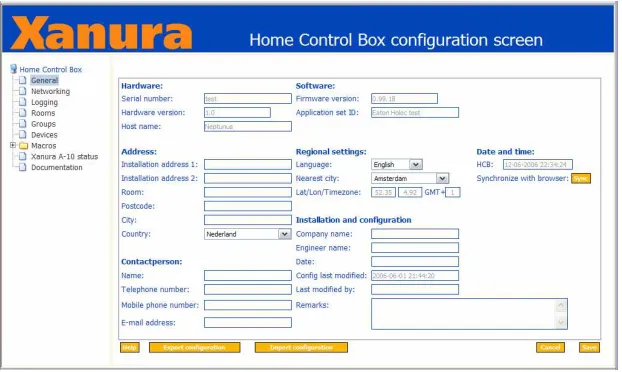
The Configuration interface will be used by people that want to change some of the underlying proper-ties of the system. This will in practice be only a small percentage of the entire usage of the UIs, and will most likely primarily take place when the system is first installed. An example of such an interface is the HCB Configuration Screen depicted in Figure 4-b below.
Figure 4-b. The Home Control Box configuration screen of the legacy Perl Application
G.J.M. Braam - 27 - MM & MM UI
the same light. This switch is connected to or part of a home automation component like the Xanura DAIX10 in Figure 2-b that sends this command to the HCB. The event is exactly the same in the eyes of the application logic, except now this input event can also be used as a logical condition in a previ-ously composed scenario now primarily limited by the imagination.
The modalities used for output towards a user are limited by what devices are available on the market today and by the processing power the combined devices possess. Phones, PDAs and sophisticated re-mote controls are capable of visual and audio output, with sometimes even vibration. Home automation devices like dimming and switching actors can also be used for output: as long as they can change the state of a device in a way that is perceivable by a user.
Input modalities are also limited by commercial availability, the creation of suitable software and con-nection media coverage. For devices capable of displaying the graphical UIs these usually include a combination of buttons on the device, a 2D tactile interface (touch screen) or some sort of a mini joy-stick to manipulate an on-screen cursor. Embedded devices generally do not have enough processing power to be able to do speech recognition or any form of image processing. I have however heard ru-mors at HAE concerning a possible project that plans to perform speech recognition partly in hardware in the form of a specially designed chip. Another input modality, one that is already supported by the related modem hardware on the HCB, is the decoding of DTMF tones sent via a regular phone line. These two UI client groups can be served by the same set of supportive services in HCBv2 because they rely on the same underlying Data Transfer features to be supported. Features like message sending, server push message reception, sending of home layout messages Data Transfer and 24/7 connectivity solutions are provided by the framework.
Devices of all the client types discussed in§2.2 will be able to connect to the HCB over multiple con-nection media. The most frequently used medium will probably be TCP/IP over one of the two built in ethernet adapters. The TCP/IP client connections, which will communicate by means of BoxTalk mes-sages, will be handled by special extensions built into a small web server which is further discussed in§4.1.6 ‘External Communication’.
4.1.3. Core
The HCB Core deals with all the intelligent handling of BoxTalk messages. It is subscribed to receive all messages so it can keep track of all events that happen in and around the HCB.
The Core also handles execution of macros written in a dynamic scripting language and manages user timers and variables. It will determine when to execute macros based on conditions. These conditional sections of the macros can depend on a large number of triggers like device actions, relative & absolute dates & times, specific values for variables or timers. Also states of devices or the changes of these states can serve as a trigger for macro execution.
The then executed macros can generate BoxTalk commands for the configured actor devices (turning on a lamp), built-in actions (turning off LED #4 on the HCB) and Service Center functionality (sending an SMS message to a user). In a macro you can also manipulate user variables and timers, thereby influ-encing the execution of other macros which in turn enables the construction of more complex systems that behave somewhat like state machines.
The language that will be used for the macros as well as the reasons for this choice are described in
§4.2.3 ‘Scripting Language’.
G.J.M. Braam - 28 - MM & MM UI
4.1.4. Drivers
Drivers are a very important part of the HCB. Their flexibility and the ease with which they can be de-veloped are imperative to the commercial success of the HCB. The HCB presents itself as an integration platform to combine multiple home automation technologies that are normally incompatible with each other. The support of a protocol that has already been standardized or the support of a very new and not yet common technology must be easy to add and with a minimum of development time.
A driver creates a link between two sides, the BoxTalk Interface and the Device Hardware Interface:
BoxTalk Interface
The BoxTalk Interface is the side that receives and sends messages in the internal BoxTalk format. All internal non-hardware communication with the driver is handled through BoxTalk messages. This side uses functions from a library to receive, parse the XML and get information from the incoming BoxTalk messages. Also library functions are being used to create BoxTalk messages and set various parameters in them before they are sent.
Hardware Devices
The other side is the side that interfaces with specific hardware that is present inside or connected to the HCB. This part has its own polling loop or preferably interrupt-based handling, and can send BoxTalk messages when appropriate events occur. Examples of these are the drivers currently under development for the home automation standards A10/X10, Konnex and Zigbee.
A driver process is managed by a special library that is linked to each driver. This library basically con-trols how the driver executable is initialized, starts the autonomous part, automatically handles the more platform-generic incoming BoxTalk messages and finally how the driver itself is terminated. More on the BoxTalk Driver model and how a driver functions exactly can be found in §4.3.3 ‘Driver Model’ below.
4.1.5. Internal Communication
All internal communication is handled centrally by a process dubbed the Communication Controller. A central approach was chosen over a distributed approach for a number of reasons:
a single point of entry, so there is no discovery overhead;
the least amount of communication channels, just one per driver; all routing logic is handled in one place;
easy logging and debugging of all messages that are sent; clear separation between internal and external communication.
The resulting central approach clearly provides the most efficient solution. A strong reason to go for a distributed approach would be the inherent robustness, but this reason does not weigh up to the ones in favor of the central approach. However, to heighten the robustness, measures are being taken to make sure that the drivers are able to reconnect to the Communication Controller without problems and that all connected processes end up in the same state as before.
The Communication Controller serves as a central hub that takes care of all internal BoxTalk communi-cations. All Drivers associate themselves with the Communication Controller when they start up. All BoxTalk messages are sent to this process, which in turn routes them to the correct destination device or devices. All routing and addressing functionality is placed in the Communication Controller, the driver processes are relatively simple, relying on the Communication Controller to deliver their BoxTalk messages. Each device can subscribe itself to services of other devic