A Monthly Double-Blind Peer Reviewed Refereed Open Access International e-Journal - Included in the International Serial Directories International Journal in IT and Engineering
http://www.ijmr.net.in email id- [email protected] Page 86 AN ASSESSMENT OF MICROCONTROLLER SYSTEM DESIGN IN ADVANCE ENCRYPTION
STANDARDANALYSIS AND FINDINGS OF THE STUDY
NurulHasan Shaikh1, Dr. Yash Pal Singh2
Department of Electronics and Communication Engineering
1,2
OPJS University, Churu (Rajasthan) – India
Abstract
VFD operation requires three fundamental areas: the rectifier, dc link, and Microcontroller. The AC power supply delivers a sinusoidal wave. The positive voltage makes a current stream in one direction, and a negative voltage makes a current stream in the inverse direction. A lot of energy is transmitted proficiently finished extraordinary distances. Before rectifier, line separating is done to decrease the commotion entering the hardware from business power lines or clamor created from electronic gear. Basic mode stifles, line sidesteps capacitors, and Metal Oxide Varistors (MOV) are for the most part utilized as channel devices for smothering AC Electromagnetic Interference (EMI). There are two modes, regular mode (line to ground) and differential mode (line to line). Channels are intended to smother Radio Frequency Interference (RFI) and EMI that exists in these modes.
1. INTRODUCTION
The capacitor acknowledges this voltage (power) from the rectifier stores it and conveys a smooth voltage to the microcontroller piece. Inductors, gags or comparative things include inductance and give all the more smoothening to yield voltage. The last area of VFD is a microcontroller [1].
The microcontroller requires a steady dc voltage at its info. A voltage control circuit gives this steady voltage. A voltage controller changes over the unregulated dc voltage got from the extension rectifier into managed dc voltage. It gives a consistent dc
A Monthly Double-Blind Peer Reviewed Refereed Open Access International e-Journal - Included in the International Serial Directories International Journal in IT and Engineering
http://www.ijmr.net.in email id- [email protected] Page 87 Subsequently, the redressed yield of the
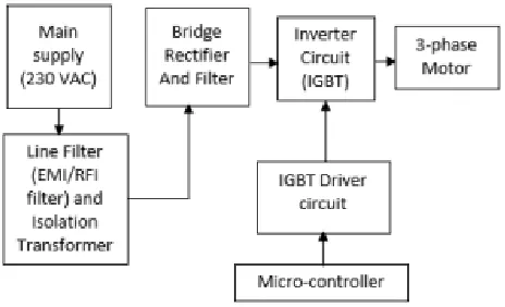
extension rectifier which is separated utilizing DC link is made steady utilizing a voltage controller circuit. A driver circuit is utilized to drive the gate of the IGBT's. This circuit involves TLP250 and IR2110. TLP250 is an eight stick power MOSFET or IGBT gate drive opt coupler comprising of a LED and photograph indicator. IR2110 is a high voltage; high-speed Power MOSFET/IGBT
driver with free high and low side yield channels. The deplete terminal associated with high voltage in the system, and subsequently, the driver circuit is acquainted with support the gate of IGBT, as the gate terminal must be no less than 10 volts higher than deplete terminal for the IGBT to lead. Figure2 is the adjusted square graph demonstrated as follows [3].
Figure 1: Modified Block Diagram
2. PULSE WIDTH MODULATION (PWM) MICROCONTROLLER
Pulse Width Modulation (PWM) is the procedure that alters the width of the pulses in a pulse prepares in a direct extent to a little control flag. For a PWM circuit, a sinusoid of wanted frequency is utilized as a control voltage. Hence, it is conceivable to create a high power waveform. The normal voltage fluctuates sinusoidally in a way reasonable for driving AC controllers. The controller speed is settled when the controller is associated directly with the AC line.
Variable Frequency Drives (VFD) change the speed of controller by changing voltage and frequency of the power provided to the controller. To keep up legitimate power factor and lessen over the top heating of the controller, the nameplate volts/hertz ratio must be kept up. This is the main task of Variable Frequency Drive [4].
A Monthly Double-Blind Peer Reviewed Refereed Open Access International e-Journal - Included in the International Serial Directories International Journal in IT and Engineering
http://www.ijmr.net.in email id- [email protected] Page 88 2. VFD control speed of controller by
varying output voltage and frequency through sophisticated microprocessor controlled electronics device.
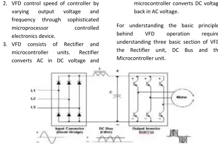
3. VFD consists of Rectifier and microcontroller units. Rectifier converts AC in DC voltage and
microcontroller converts DC voltage back in AC voltage.
For understanding the basic principles behind VFD operation requires understanding three basic section of VFD: the Rectifier unit, DC Bus and the Microcontroller unit.
Figure 2: VFD Circuit Diagram
3. CONSTANT V/F RATIO OPERATION
All Variable Frequency Drives (VFDs) keep up the yield voltage – to – frequency (V/f) ratio steady at all speeds for the reason that takes after. On the off chance that a similar voltage is connected at the decreased frequency, the magnetic motion would increment and soak the magnetic center, fundamentally mutilating the controller performance. The magnetic saturation can stay away from by keeping the ϕm steady. Also, the control torque is the result of stator transition and rotor current. For keeping upthe appraised torque at all speeds, the consistent motion must be kept up at its evaluated esteem, which is
A Monthly Double-Blind Peer Reviewed Refereed Open Access International e-Journal - Included in the International Serial Directories International Journal in IT and Engineering
http://www.ijmr.net.in email id- [email protected] Page 89
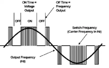
How Drive Changes Motor Speed
Figure 3: Drive Output Waveform Components
Thus the carrier frequency is derived from the speed of the power device switch remains ON and OFF. It is also called switch frequency. Therefore higher the carrier frequency higher the resolution for PWM (Pulse Width Modulation) contains. The typical carrier frequency ranges from 3KHz to 4 KHz or 3000 to 4000 times per second as compared with older SCR based carrier frequency which ranges from 250 to 500 times per second.
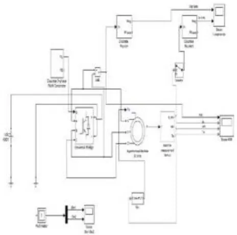
Simulation Circuit
For variable speed control of AC electrical machines a few power devices switches, for example, IGBTs, MOSFETs and GTO use as constrained – compensation technique.
A Monthly Double-Blind Peer Reviewed Refereed Open Access International e-Journal - Included in the International Serial Directories International Journal in IT and Engineering
http://www.ijmr.net.in email id- [email protected] Page 90 Figure 4: Simulation Circuit of VFD
4. THREE-LEVEL NEUTRAL POINT CLAMPED MICROCONTROLLER
Rather than including a part in the middle of the drive and the controller, adjusting the power topology to diminish the issues depicted above is a much reasonable approach. Yaskawa Electric Corporation was the primary drive maker to turn out with a three-level drive structure for broadly useful low voltage application. The three-level drive topology utilized by Ya.skawa is known as the Neutral Point Clamped three-level microcontroller. The unbiased point braced (NPC) three-level microcontroller was presented first by A. Nabae, I. Takahashi and H. Akagi in 1980 and distributed in 198. In this item, a novel technology is utilized to accomplish balancing of the dc transport capacitor voltages. Details are portrayed in the
accompanying segments. Figure 4 demonstrates the circuit outline of the NPC three-level microcontroller.
Each stage has four exchanging devices (IGBTs) associated with the arrangement. Taking stage U for instance, the circuit acts in an accompanying way. At the point when IGBTs Qui and Qu2 are turned on, yield U is associated with the positive rail (P) of the de transport. Whenever Qu2 and Qu3 are on, it is associated with the mid-point (0) of the de transport, and when Qu3 and Qu4 are on, it is associated with the negative rail (N). Therefore, the yield can take three voltage esteems contrasted with two esteems for the regular two-level topology. The connection between the exchanging states of IGBTs and the subsequent yield voltage regarding the dc mid-point is
A Monthly Double-Blind Peer Reviewed Refereed Open Access International e-Journal - Included in the International Serial Directories International Journal in IT and Engineering
http://www.ijmr.net.in email id- [email protected] Page 91 Figure 5: The Neutral Point Clamped three Level Microcontroller Circuit Topology
Table1: Relation between Switch in -States and Output Voltage
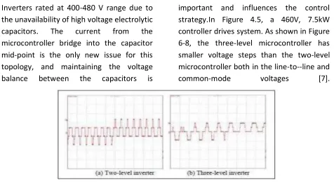
Inverters rated at 400-480 V range due to the unavailability of high voltage electrolytic capacitors. The current from the microcontroller bridge into the capacitor mid-point is the only new issue for this topology, and maintaining the voltage balance between the capacitors is
important and influences the control strategy.In Figure 4.5, a 460V, 7.5kW controller drives system. As shown in Figure 6-8, the three-level microcontroller has smaller voltage steps than the two-level microcontroller both in the line-to--line and
common-mode voltages [7].
A Monthly Double-Blind Peer Reviewed Refereed Open Access International e-Journal - Included in the International Serial Directories International Journal in IT and Engineering
http://www.ijmr.net.in email id- [email protected] Page 92 Figure 7: Measured Surge Voltage at Controller Terminals, V: 500V/Div, T: 50ms/Div
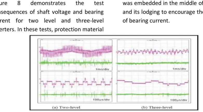
Figure 8 demonstrates the test consequences of shaft voltage and bearing current for two level and three-level inverters. In these tests, protection material
was embedded in the middle of the bearing and its lodging to encourage the perception of bearing current.
Figure 8: Shaft voltage and bearing Current Upper in each frame: shaft voltage, 10V/div Lower in each frame: bearing current, 20mA/div
CONCLUSION
In this examination, the present status of the controller drives industry is displayed. All parts of the controller drives industry have not been secured because the subject is excessively included and excessively huge, making it impossible, making it impossible to be secured here. Remarkable
A Monthly Double-Blind Peer Reviewed Refereed Open Access International e-Journal - Included in the International Serial Directories International Journal in IT and Engineering
http://www.ijmr.net.in email id- [email protected] Page 93 REFERENCES
[1]. Linköping, Sweden, "Contrbution in control strategies of flow on-Demand-Hydraulic circuits", The 13th Scandinavian International Conference on Fluid Power, SICFP2013, June 3-5, 2013.
[2]. Wahid, A. Sayed, and Yehia. El-Mashad, May 2002, “Fuzzy Control of Highly Sensitive Dynamics Behaviors of Variable Displacement Axial Piston Pump”, proceeding of the 10th Int. AMME conference, Egypt.
[3]. G.S. Virk and A. Al-Dmour, Jan.2004 “System Simulation Using Neural Networks”, Departmental
Research Report No. 537, University of Bradford.
[4]. J. Jantzen, 30 Oct 2008, “NeurofuzzyModelling”, Bldg 326, DK-2800 Lyngby, DENMARK Tech. report no 98-H-874 (nfmod). [5]. D. Nauck and R. Kruse, 2009,
“Neuro-Fuzzy Systems for Function Approximation”, Fuzzy Sets and Systems (101)2 pp. 261-271. [6]. Habibi, S., 2001, "Lecture Notes:
Control System I", Department of Mechanical Engineering, University of Saskatchewan, Canada.