Generation of Low Sidelobe Radiation
Patterns with Narrow Beams for the
Suppression of EMI in Radar Receivers
B.Ramana kumar
1, Prof.P.Mallikarjuna Rao
2, Prof.G.S.N.Raju
3Research Scholar, Department of E.C.E, A.U College of Engineering (A), Visakhapatnam, Andhra Pradesh, India1
Professor, Department of E.C.E, A.U College of Engineering (A), Visakhapatnam, Andhra Pradesh, India2
Vice Chancellor, Centurion University, Visakhapatnam, Andhra Pradesh, India3
ABSTRACT: Pencil beams with narrow beam-width are required for range resolution of targets. In general, all the beams are associated with the number of side lobes around main beam. The presence of high side lobes causes electromagnetic interference in Radar receivers due to nearby objects. Under these circumstances the radar system is susceptible to jamming. It is therefore, interesting to design an array antenna in order to generate very narrow beam width with very low side lobes. In this work a new highly tapered amplitude distribution function is suggested and radiation patterns are evaluated numerically. The resultant radiation patterns contain side lobes of the order of -59.8dB. These low sidelobed radiation patterns are useful for all the applications.
KEYWORDS: Radiation pattern, Low sidelobe, Narrow beamwidth.
I.INTRODUCTION
Pencil beams are required to achieve range resolution of targets. In fact, these are also used for point to point communication purposes. These beams are usually associated with number of side lobes around the main beam. The presence of high side lobe levels results in electromagnetic interference in the radar receiver due to nearby objects. Sometimes, this EMI is high, that it may mask the required echo completely. It is therefore essential to reduce the side lobe levels to the minimum extent possible.
A number of techniques for the production of these beams are available in the literature [1-3]. When the antenna’s major dimension is sufficiently large, geometrical/optical principals are used to establish the design parameters qualitatively. However, to establish the quantitative characteristics of the pencil beam, it is necessary to take into account the diffraction effects. The main problem is to transform the spherical wave front from a point source into a system of parallel rays, that is, a planar wave front in the aperture plane of reflector. This transformation is achieved by a point source located at the focal point of paraboloid of circular symmetry.
aperture. The radiation of the far field is numerically evaluated and results are presented. It is found from the results that the present highly tapered distribution function is most suitable to suppress EMI completely in radar receivers as the resultant beam contains negligible order of side lobes. The radiation patterns are computed both for continuous line source as well as for an array of discrete radiating elements.
II.RELATEDWORK
R.S.Elliot [5] has described a design method for the creation of line source that results an antenna radiation pattern consisting of a narrow beam with low sidelobes.The resultant sidelobe levels are different on the two sides of the main beam. The author also discussed main beam offset and the characteristics of the associated different pattern in his work. In this work,the incremental gain resulting from assemmetric sidelobes is analysed and the corresponding data is presented for the typical cases.Experimental verification results of the praposed design technic is also achieved with 19 element slot array is also being presented in X band.
R.P.Doole [6] suggested a method for the optimum design of small nonuniformly spaced arrays. In this work an efficient computational algorithm is developed for determining the optimum design of small nonuniformly spaced arrays. The resulting design involves the location of antenna elements is such that, the radiation pattern function has the smallest possible sidelobe level. The results shows that an improvement in the sidelobe level of 1.7dB for an array of 9 elements and it is achieved by simply arranging the elements assemmetrically.
Linear arrays of arbitrary located elements has been considered by Unz [7].The elements of the array are related to the far-field radiation pattern in the form of a matix. The quality factor and the lower bound of the stored energy are determined and the figure of merit of the array is defined. The approach is found to be suitable to extend for the cases of two and three dimensional arrays.
The line source antennas are designed by Taylor [8] for the generation of radiation pattern with low sidelobes and narrow beamwidths. The array of large number of elements are conveniently analysed by treating them as continuous distributions. The patterns of line source are found to contain both the elements and space factors. As it is well known, the element factor depends upon the type and orientation of the fields or currents and it has usually little directivity. On the other hand, the factor is highly directive. It’s shape depends upon relative variation of the fields or currents along the source. The Taylor’s patterns are found to contain one main beam with two regions of sidelobes on either side. The designed amplitude distributions are found to contain pedestal towards the ends of the aperture and tapered at the central region in most of the cases.
Array distribution function has been determined using numerical approximation method by Tang[9].The method essentially involves transforming the Taylor’s line source into space tapered arrays.Properties of these arrays along with the total pattern characteristic are present.
Hyneman [10] has reported a method controlling the sidelobe envelope function for line sources.The method consists of iterative sampling to control the sidelobes. From the results obtained, it is found to have low ratios of maximum to minimum current amplitudes and low super directive ratios.
beams with low sidelobe patterns,the calculation of space distribution function is carried out for an array of N=20,40, and 200 elements.
III. FORMULAE FOR RADIATION PATTERNS
The far field pattern for a continuous line sources is given by
[1]
= amplitude distribution
= normalized array length
2L =Length of array = wavelength
, being the angle between broadside and direction of propagation Is the position on the array
In the case of a discrete array, the above expression reduces to the summation as given below
E(X) = [2] Where = source position
= Number of elements
IV.RESULTSANDCONCLUSIONS
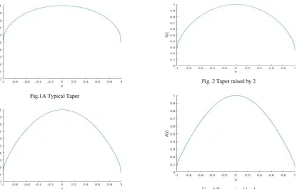
The far field radiation patterns are computed using expression [1] and [2] for an array length of 10λ, 20λ and 50λ.The results on overall radiation pattern characteristics are presented in table[1] and table[2].The resultant radiation patterns are computed for the following amplitude distributions shown in fig.[1-4].
Fig.1A Typical Taper
Fig. 3 Taper raised by 3
Fig. 2 Taper raised by 2
RADIATION PATTERN CHARACTERISTICS
Table 1: Continuous line source Distribution Array
Length ISLL dB IISLL dB IIISLL dB Last SLL dB Beamwidth (radians) Fig.1 10 -15.32 -20.40 -23.73 -33.22 0.218
20 -15.45 -20.42 -23.73 -39.84 0.108 50 -15.71 -20.66 -23.90 -48.03 0.044 Fig.2 10 -17.48 -23.00 -26.52 -36.96 0.236 20 -17.56 -23.16 -26.68 -44.11 0.120 50 -17.76 -23.55 -26.80 -52.39 0.048 Fig.3 10 -19.58 -25.77 -29.69 -40.82 0.256 20 -19.66 -25.79 -29.72 -48.32 0.130 50 -19.84 -26.10 -30.00 -56.94 0.054 Fig.4 10 -21.66 -28.47 -32.87 -44.78 0.276 20 -21.74 -28.49 -32.92 -52.66 0.140 50 -21.74 -28.84 -32.78 -59.80 0.056
Table 2 : Discrete arrays
Distribution Array Length I SLL dB II SLL dB III SLL dB Last SLL dB Beamwidth (radians) Fig.1 10 15.27 -20.30 -23.32 -29.74 0.216
20 -15.39 -20.39 -23.65 -36.41 0.108 50 -15.67 -20.45 -23.87 -44.39 0.044 Fig.2 10 -17.43 -23.00 -26.45 -33.60 0.236 20 -17.47 -23.06 -26.68 -40.34 0.120 50 -17.62 -23.47 -26.77 -48.94 0.048 Fig.3 10 -19.59 -25.81 -29.69 -37.85 0.258 20 -19.67 -25.94 -29.76 -44.89 0.130 50 -19.86 -26.10 -29.82 -53.73 0.054 Fig.4 10 -21.76 -28.46 -32.87 -42.53 0.276 20 -21.78 -28.62 -32.92 -49.66 0.140 50 -21.81 -28.89 -32.98 -58.61 0.056
It is found from the results that it has been possible to have low side lobe radiation pattern without major increase in beam widths using the above typical tapers. The results of an array of Isotropic radiators are found to be identical with those of continuous line source. For discrete array calculations, the spacing suggested by Ishimaru [12] is used. In the case of discrete radiators, the resultant pattern is the product of array factor and element pattern. The resultant low side lobe (-59.8 dB) radiation patterns are very useful for point to point communications systems.
REFERENCES
[1] M.T.Ma, "Theory and Application of Antenna arrays." John Wiley & sons, New York, 1974. [2] R.S.Elliot, “Antenna theory and design”, Prentice-Hall India, New Delhi, 1985.
[3] Bernard Stienberg D., “Principles of aperture and array system design”, John Wiley& sons, NY, 1974.
[4] P.M.Rao, G.S.N.Raju et.al. “Some studies on arrays for sidelobe reduction required for EMI control”,Proc. INCEMIC,pp.314-320,Dec.1995. [5] R.S.Elliot,’Design of line source antennas for narrow beamwidth and asymmetric low sidelobes’, IEEE Transaction on Antennas and
[6] R.P.Dooley, “The optimum design of small non-uniformly spaced arrays”,IEEE transaction on antennas and propagation,vol.AP-20,pp.636-637,Sept.1972.
[7] H.Unz, ‘Linear arrays with arbitrarily distributed elements”, IRE Transection on Antennas and propagation, vol.AP-8,pp 222-223, March 1960. [8] T.T.Taylor, “One parameter family of line sources producing modified Sin u)/ u) pattererns.” Huges Aircraft Co. Tech. Mem.324,Culver
city, California. Contract AF 19(604) – 262- F -14, 4 Sept. , 1953.
[9] C.H.Tang, “some numerical results for space tapered arrays” IEE Transection on Antennas and propagation, vol.AP-14,pp.391-392,May 1966. [10] R.F.Hyneman, “A technique for the synthesis of line source antenna patterns having specified sidelobe behavior,” IEEE Transaction on
Antennas and propagation, vol.AP-16, pp.430-435, July 1968.
[11] P.M.Rao, & G.S.N.Raju, “Generation of low sidelobe radiation patterns for minimizing possibleEMI”, EMC Journal,vol.9, PP. 15-22, April& Oct.1996.