ABSTRACT
BUCK, CHRISTOPER RAY. High-Intensity Electric Field and Non-Premixed Propane Diffusion Flame with Co-Flow: Apparatus Design and Experimentation. (Under the direction of Dr. Kevin Lyons.)
This thesis focuses on the design and implementation of an apparatus and control system for the investigation of effects high-intensity electric fields have on non-premixed propane diffusion flames with co-flow. A detailed analysis of design considerations was performed. From this analysis, an apparatus and control system was designed to facilitate experimentation on the afore mentioned effects. Upon implementation, a series of
experiments were performed to establish baseline behaviors of these flames without the addition of the electric field, followed by an experiment to investigate reattachment voltage thresholds. Baseline experiments were prescribing fuel flow rates and adding co-flow until the flame was forced to lift. Further addition of co-flow was then applied until blowout occurred. A brief discussion of lifted flame architecture reveals the presence of a tribrachial flame under co-flow conditions. This tribrachial flame is considered stable, or pseudo-stable, in the lifted position. The addition of an electric field is found to force these flames to
High-Intensity Electric Field and Non-Premixed Propane Diffusion Flame with Co-Flow: Apparatus Design and Experimentation
by:
Christopher Ray Buck
A thesis submitted to the Graduate Faculty of North Carolina State University
in partial fulfillment of the requirements for the degree of
Master of Science
Aerospace Engineering
Raleigh, North Carolina 2017
APPROVED BY:
_______________________________ _______________________________
DEDICATION
BIOGRAPHY
Christopher Buck is a graduate research assistant in the Reacting Flows and Turbulent Jets Laboratory at North Carolina State University’s Department of Mechanical and
ACKNOWLEDGMENTS
TABLE OF CONTENTS
LIST OF TABLES ... vii
LIST OF FIGURES ... viii
CHAPTER 1: INTRODUCTION ... 1
Rational and Focus of Research ... 1
CHAPTER 2: DESIGN CONSIDERATIONS ... 4
Apparatus ... 5
Control Box ... 6
Data Acquisition System ... 7
CHAPTER 3: DESIGN ... 8
Control Box ... 13
Other Necessary Components ... 18
CHAPTER 4: IMPLEMENTATION ... 19
Apparatus ... 19
Control Box ... 21
CHAPTER 6: FUTURE WORK & CONCLUSIONS ... 39
REFERENCES ... 42
APPENDICES ... 43
Appendix A. Technical Drawings: Apparatus ... 44
Appendix B. Technical Drawings: Electric Field Control Box ... 61
LIST OF TABLES
Table 1: Figure 1 Component Identification ... 9
Table 2: Control Box Front View Item Descriptions ... 14
Table 3: Control Box Top View Item Descriptions ... 15
Table 4: Control Box Rear View Item Descriptions ... 17
LIST OF FIGURES
Figure 1: Apparatus Assembly Major Components... 9
Figure 2: Adjustable Electrode Mount ... 10
Figure 3: Flame Lift-Off/Electrode Height Indicator ... 11
Figure 4: Laminarization Assembly... 12
Figure 5: Control Box Front View... 14
Figure 6: Control Box Top View ... 15
Figure 7: Control Box Rear View ... 17
Figure 8 As-Built Apparatus Assembly ... 19
Figure 9: As-Built Apparatus – Electrode/Burner Side-View (Left); Laminarizing Pellets (Right) ... 20
Figure 10: Control Box As-Built – Front Panel ... 21
Figure 11: Control Box Top Panel Components – Cooling Fans (Top); Emergency Stop (Bottom) ... 22
Figure 12: Control Box As-Built – Rear Panel ... 23
Figure 13: Overall Setup ... 25
Figure 14: Apparatus Setup for Baseline and Preliminary Experiments ... 26
Figure 15: Flame Progression During Lift-Off ... 28
Figure 16: Pseudo-Stable Lifted Flame ... 29
Figure 17: Baseline Experimental Results No E-Field ... 30
Figure 18: Flame Stability Regions ... 31
Figure 20: Post-Reattachment Stabilization at 240-fps; Elapsed time 0.042-seconds ... 34
Figure 21: Voltage Required to Stabilize Flame ... 35
Figure 22: Improvements to Blowout Parameters... 36
CHAPTER 1: INTRODUCTION Rational and Focus of Research
Combustion science, and its general understanding, has come a long way since it was first harnessed by humans. The conversion of chemical to thermal energy, through
combustion, is used in a wide variety of applications including home and industrial heating, power generation, and transportation, to name a few. Because of its ability to be utilized in such a broad spectrum of applications, it has been revered as one of man’s greatest
achievements, second only to language. Yet as a whole there is, still, much to be learned. As of late, new theories have arisen sparking investigations into how high-intensity electric fields effect the combustion process and the stability of flames in the laboratory environment. Investigating these effects requires some understanding of the mechanics involved in the combustion process, specifically its role in lifted flame architecture, and the generation of ionic wind via high-intensity electric fields in air.
A lifted flame in a non-premixed jet are tribrachial consisting of three resident flame types. These three flames, a diffusion flame, a lean premixed flame, and a rich premixed flame, coexist in different regions of the tribrachial flame. Chung investigated the stability of these flames. He showed that not all fuels are capable of producing stabilized lifted flames and that this was highly correlated to the fuel’s Schmidt number (Sc), a ratio of momentum diffusivity and mass diffusivity, or viscous diffusion rate and mass diffusion rate. Fuels with 𝑆𝑐 < 1 are incapable of producing lifted flames while fuels with 𝑆𝑐 > 1 are [1]. This implies
lifting process, the transition from nozzle-attached to lifted, is explained is terms of the boundary velocity gradient which is the velocity gradient in the mixing layer of the fuel jet [2]. Further, experimental observations support this theory for propane [3].
Electric fields, when applied across an air gap, influences air in different ways. One of which, ionic wind, is discussed here as it plays a key role in the reattachment and
stabilization of the flames investigated. In the late 1800’s, Chattock set out to empirically determine to what extent these fields influenced air by considering the mass and velocity of the flow of ions between two electrodes in air. He found that the ionic wind, or electric wind as he called it, produced by the flow of electrons was capable of producing a measurable pressure when stagnated on a plate. Further, he derived equations to calculate the velocity of this flow based on electric potential and gap size between electrodes. He concluded that the
flow of positive and negative ions in the field produces a flow velocity of 3.2𝑣𝑜𝑙𝑡 𝑐𝑚−𝑔𝑎𝑝⁄𝑐𝑚 𝑠⁄ .
His work shows that the production of this ionic wind is due to the momentum transfer from the ion to the air in conjunction with local ionization of air molecules [4]. It is beneficial to maximize the production of ionic wind for reattachment and stabilization of flames. This is accomplished by focusing the coronal discharge at a point. This is accomplished, for the research presented here, by applying the field with a fine tipped electrode [5].
AC and DC electric fields have both been applied to flames. AC fields produce a bi-ionic wind alternating directions with current. It has been found that AC fields have minimal effects on flame stability and, in some cases, lowered the blow out velocities at low
frequencies [6]. This leads to the implication that the stabilization effects are highly
dependent on the polarity of the field. Intuitively, positive polarity (ie. Fuel nozzle cathode with an anode electrode) is necessary to orient the ionic wind in the proper direction for stabilization [7].
The application of DC electric fields has resulted in the reduction of soot production. This is accomplished by limiting the residence time of soot particles in soot generation regions of the flame and by manipulating soot particles forcing them to break down and oxidize in oxygen rich regions of the flame [8]. The reduction of soot emissions promotes the positive impact research into electro-flame interaction could have on combustion dependent process and emission control.
The experiments presented in this thesis utilizes a non-premixed propane flame with the addition of co-flow. This is a continuation of work done by Kribs. His work investigated the stabilization of partially-premixed jet flames without co-flow. His findings, agreeing with Chung et al., show that the positive configuration, described previously, is the most
CHAPTER 2: DESIGN CONSIDERATIONS
Preliminary research provided an extensive evaluation of how to approach the overall design of the setup presented herein. The following presents these considerations split into two subsections, apparatus and control box, each with a series of categories, data acquisition, ease of use, safety concerns, and practicality. In order to facilitate the design process, a series of questions were formulated. These questions are as follows:
1) What are the independent and dependent variables to be investigated?
The apparatus and control box must facilitate the acquisition of: flame lift-off height, co-flow and fuel mass co-flow rates, electric field voltage and current values, and electrode height above the nozzle.
2) What other variables must be avoided during experimentation?
The variables that must be excluded from the results are co-flow turbulence, turbulence and mixing resulting from ambient air movement.
3) How will the complexity of the interaction between these variables be deciphered into tangible results? i.e. What data quantities must be acquired to fully investigate the phenomena?
Combustion research comes with a substantial list of safety concerns: leaking fuel, exhaust gas buildup leading to asphyxiation, unintentional ignition, and burns, to name a few. These concerns are relatively acknowledged and understood by most. In
comparison, dealing with high-voltage electric fields presents its own list of safety concerns that may not be as intuitive and can have more devastating results as to those with combustion.
5) How might this setup need to be modified to further investigate the findings it produces?
Future modifications to the apparatus may require an entirely new design. The control box will need to be a standalone device that can be easily implemented on any apparatus. Additionally, the addition of an automated data acquisition system may be desired. Exterior connections to the field monitors, spatial allowances, and DC supply power options should be considered in the design.
6) What budgetary constraints must be satisfied to make this design implementable? As with all engineering design proposals, the total cost of a design can be the deciding characteristic as to whether or not the design is approved for production. Reducing costs to accommodate budgetary constraints can prove to be an arduous task
Apparatus
The apparatus must be able to provide a safe, easy to use, contamination free environment. The apparatus design considerations are as follows:
The bulk of the apparatus must be constructed of non-conductive materials.
The apparatus must be shielded from ambient airflow.
Fuel and air supply lines must be made of non-conductive materials.
The co-flow must be laminar to avoid introducing turbulent mixing.
A simple method for determining lift-off height must be implemented.
Electrode height must be adjustable and readable.
Fuel flow rates must be monitored.
Air flow rates for the co-flow must be monitored.
Charged components must be easily accessible for discharging any residual energy.
Control Box
The control box will be used to introduce the electric field and monitor its parameters. As with the apparatus, the control box must be able to provide a safe and easy to use
interface during operation. The key design parameters for the control box are as follows:
The control box must be constructed of insulating materials.
All electrical components should be UL listed.
Power Supply cooling may be a concern which must be addressed.
Simple and intuitive operation should be implemented.
The power supply input circuit should be isolated from all other devices.
There must be a safe method to deal with residual charges.
The enclosure must be sized to accommodate all necessary components.
A comprehensive operations manual must be provided.
Data Acquisition System
The Data Acquisition System (DAQ) facilitates the recording of key variables during experimentation. Initially, the DAQ will be of a primitive type requiring data to be taken manually and recorded in tables. The key variables which must be recorded are as follows:
Fuel Flow Rate
Co-Flow Flow Rate
Electrode Height
Electric-Field Voltage
Electric-Field Current
Flame Lift-Off Height (Where applicable)
CHAPTER 3: DESIGN
Careful attention to the preceding design considerations was taken to ensure a safe and effective setup. Each aspect of the apparatus and control box was examined and designed to facilitate proper functionality, meet facility safety regulations, and optimize data
acquisition and accuracy. The following describes each portion of the design and justifies its final configuration.
Apparatus
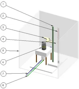
Figure 1: Apparatus Assembly Major Components
Table 1: Figure 1 Component Identification
Item Description
1 Electrode Mount Guide Rail 2 Flame Lift-Off Height Indicator 3 Electrode Mount
4 Fuel Delivery Nozzle/Exit Plane 5 Ambient Air Shield
6 Co-Flow Containment/Laminarization Assembly 7 Compressed Air Supply Line
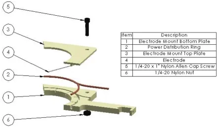
Figure 2: Adjustable Electrode Mount
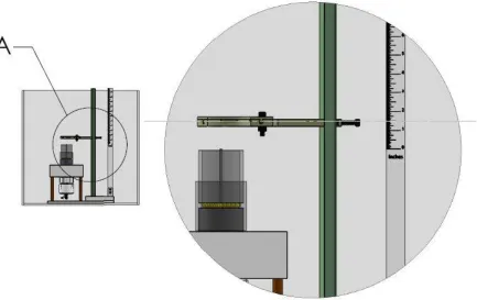
Figure 3: Flame Lift-Off/Electrode Height Indicator
The flame lift-off height indicator’s purpose is twofold. First, the indicator, mounted coplanar to the centerline of the fuel nozzle, provides a reference scale when analyzing visual data. Second, the indicator allows for convenient, accurate, electrode height adjustment. Previously, the flame height indicator consisted of a wooden ruler mounted in the same location. This design accomplished the same purpose, but, due to the height of the exit plane above the base of the apparatus, two readings from the ruler were required to fully measure the flame height. The revised indicator, Figure 3, is constructed of a 1” wide strip of acrylic on which evenly spaced ticks have been laser etched starting with “0” inches at the exit plane
no ambient light. The acrylic indicator has been designed to accommodate such situations and can be illuminated from above or below causing the etched surfaces to glow.
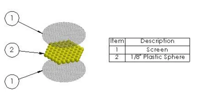
Figure 4: Laminarization Assembly
Control Box
The control box was designed to accommodate each of the key parameters listed in chapter 2. The following section will look at each aspect of the control box design, elaborate on their intended use, and explain the thought process that was used.
The enclosure is constructed of ¼” acrylic. Acrylic is an excellent insulator, easily
Figure 5: Control Box Front View
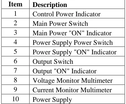
Table 2: Control Box Front View Item Descriptions
Item Description
1 Control Power Indicator 2 Main Power Switch
3 Main Power "ON" Indicator 4 Power Supply Power Switch 5 Power Supply "ON" Indicator 6 Output Switch
The control box produces and monitors the electric field applied to the apparatus. Figure 5 shows the key components and their functions. All necessary controls, indicators, and readouts are easily visible/accessible from the front of the control box to facilitate easy operation and data recording.
Figure 6: Control Box Top View
Table 3: Control Box Top View Item Descriptions
Item Description 1 Cooling Fan
Figure 7: Control Box Rear View
Table 4: Control Box Rear View Item Descriptions
Item Description
1 Multimeter GFCI Recepticle 2 Power Supply Power
3 Control Power
4 Cooling Holes (Bottom) 5 24V Control Power Supply 6 High Voltage Output Return 7 Grounding Rod
8 Power Supply Output
Fully detailed technical drawings for the apparatus and control box can be found in Appendices A and B.
Other Necessary Components
CHAPTER 4: IMPLEMENTATION
Implementation, of the control box and apparatus, requires a comprehensive understanding of how the two devices work. The following figures illustrate the as-built configurations, apparatus and control box, of the design and a typical setup for
experimentation.
Apparatus
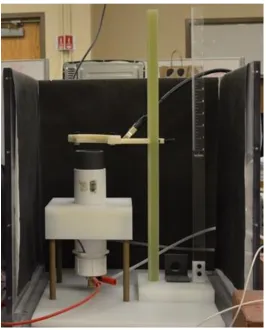
Figure 8 shows the as-built apparatus assembly as it appears during operation. Two large electrode claps can be seen. One attached to the power distribution ring originating from the control box output terminal. The other to the base of fuel nozzle originating from the control box output return terminal. The ambient air shield can also be seen covered in a black material. Covering the shield is necessary to eliminate any glares or reflections, which could contaminate data, and provide a high contrast background to the flame being
examined. This figure also demonstrates the functionality of the laser etched ruler mounted to the right of the electrode mount rail. The setup shown indicates an electrode height of 1”
above the burner nozzle exit plane.
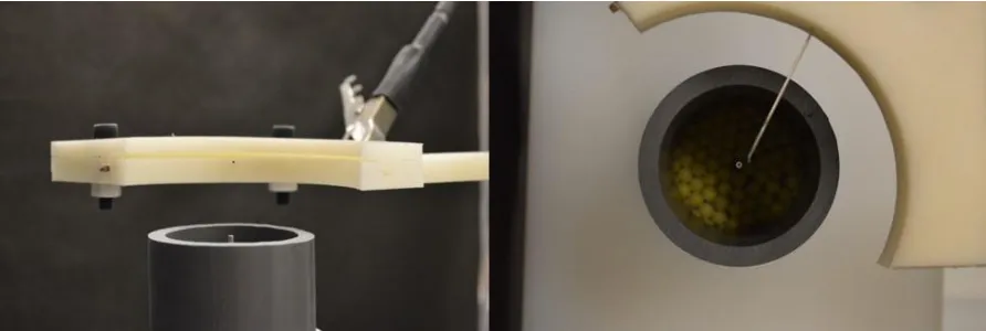
Figure 9: As-Built Apparatus – Electrode/Burner Side-View (Left); Laminarizing Pellets
(Right)
customization of electrode position radially in relation to the nozzle. The ability to adjust the tip of the electrodes position allows for investigation into the effects of the electrodes
presence on the combustion/mixing process with and without an electric field. The presence of the electrode, which is cylindrical in shape, will influence the mixing, via vortex sheading when 𝑅𝑒𝑑 > 40, of the fuel with air downstream of the electrode. It is important to have the
ability to incrementally adjust the electrodes penetration into the flow. Examples of this effect can be seen in the preliminary findings portion of this document.
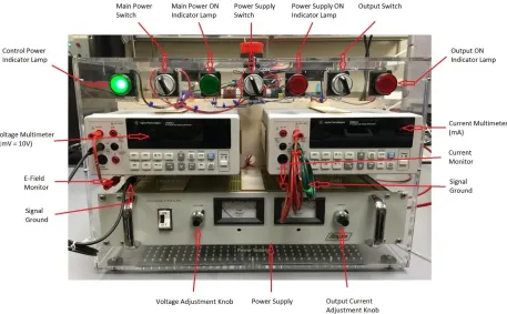
Control Box
Figure 10 shows the final front face of the control box. As can be seen all components clearly fit into the box and all switches and indicators are clearly visible. It should be noted that the multimeters did not allow for internal wiring. The power supply voltage and current monitor outputs were routed from the rear of the power supply to the front panel. Barrel jacks were used to continue the routing to the face of each multimeter.
Figure 11: Control Box Top Panel Components – Cooling Fans (Top); Emergency Stop
(Bottom)
internal electrical code satisfying safety regulations applicable to control cabinets. Examples of the attention to detail can be seen above.
Figure 12: Control Box As-Built – Rear Panel
The rear panel of the control box, Figure 12, houses all the electrical inputs and outputs required. Organization of this panel was done by grouping the types of connections into two categories, 120V input power and power supply components. Two distinct input power cords were used to isolate the power used by the power supply and the power used by the peripherals. The power supply cord is run through the back panel and directly to the power supply. The control power cord is run through the back panel and to a power
left-center. The 24V transformer supplies all indicators and the two cooling fans. The GFCI receptacle supplies power to both multimeters. The nature of high-voltage power and the high cost of laboratory equipment prompted the use of this receptacle to safe guard the multimeters from accidental short circuiting while in use.
Typical Setup
The typical setup illustrates how the overall system, control box and apparatus, works to facilitate experimentation. Figure 13 shows the setup as it appears prior to
Figure 13: Overall Setup
Figure 14: Apparatus Setup for Baseline and Preliminary Experiments
CHAPTER 5: PRELIMINARY FINDINGS
Using the experimental setup described in chapter 4, a series of experiments were performed. These experiments sought to establish baseline flame behaviors associated with this setup. The following details the results of these experiments and discusses the
implications of the observations made during experimentation.
Experiment 1: Established Baseline Results.
The baseline flame behaviors were investigated in two parts. The first was to establish the fuel flow rates at which a propane, 𝐶3𝐻8, flame becomes detached from the nozzle and
blows out without co-flow or an electric field. The second was to determine how lift-off and blowout are affected by the introduction of co-flow.
Table 5: Experiment 1 Part A; Baseline Lift-Off and Blowout
Volumetric Flow Rate
(𝑚3⁄ ) ×10𝑠 −5 Reynolds Number
Lift-Off 5.179 10484
Blowout 8.963 18145
Part B of experiment 1 investigates the how the addition of co-flow effects these results. It is expected that the introduction of co-flow will have minimal effects on mixing prior to the flame front and will “push” the flame off the nozzle at fuel flow rates well below that of those found in Table 5. This was examined by setting a prescribed fuel flow rate and slowly increasing the co-flow rate until lift-off and blowout occurred. Additionally, a series of trials was conducted to determine the co-flow rate at which a lifted flame would naturally stabilize and reattach to the nozzle exit plane.
Figure 15: Flame Progression During Lift-Off
depict in still images and the mechanism responsible for this behavior, most likely turbulence, has yet to be fully studied.
Figure 16: Pseudo-Stable Lifted Flame
Figure 17: Baseline Experimental Results No E-Field
The baseline results, Figure 17, show linear trends for lift-off, blowout, and natural reattachment of the propane flame. It should be noted that at very low fuel flow rates, 𝑅𝑒 <
2000 lift-off occurred, as seen, but did not stabilize. Hence the lack of blowout data points below 𝑅𝑒 = 2000. Also, take note that the natural reattachment data density is much lower
than that of lift-off and blowout. Despite the low point density, the natural reattachment data y = -0.199x + 2000.1
R² = 0.9646 y = -0.1167x + 2113.1
R² = 0.9835
y = -0.4649x + 1893.4 R² = 0.9971
0 500 1000 1500 2000 2500
0 2000 4000 6000 8000 10000
Co
-Flow
Re
Fuel Re
Base Line Lift-off Blowout and Reattachment Trials
and blowout conditions for the flames in question. Thus, the lift-off data density is much higher than that of the other two events shown.
Figure 18: Flame Stability Regions
produce no flame. Now that the natural behavior of the flame is established, prescribed conditions can be applied to study the effects the electric field has on the flame’s stability.
Experiment 2: Required Voltage for Reattachment of a Lifted Flame
Figure 19: Reattachment Progression at 240-fps; Elapsed Time 0.083-Seconds
The progression in Figure 19 illustrates the time scale of the reattachment process once the required attachment voltage is applied. There are some additional observations that can be made while examining this progression. Images a-p show a distinct irregularity at the base of the flame. The base of the flame tends to propagate towards the nozzle, in an
antisymmetric manor, favoring the region farthest away from the anode. It is thought that this is, in part, due to the ionic wind produced by the flow of electrons from the anode to the cathode. Images q and r show the instances just before and after reattachment occurs,
Image r shows the moment at which the flame reattaches to nozzle reducing the resistance experienced by the field and producing a fully connected arc from anode to cathode.
Figure 20: Post-Reattachment Stabilization at 240-fps; Elapsed time 0.042-seconds
Figure 21: Voltage Required to Stabilize Flame
Figure 21 shows the voltage applied to the system at which the flame reattached to the nozzle and stabilized for different Reynolds number ratios, 𝑅𝑒𝑓𝑢𝑒𝑙⁄𝑅𝑒𝑐𝑜−𝑓𝑙𝑜𝑤. As seen in
the figure, there is a sharp increase in required voltage around the Reynolds number ratio of 3.5 followed by a small spike and a relatively linear set of points. This indicates that the required voltage to reattach the flame is not necessarily a function of flow rates. What is not seen here is that the flame’s lift-off height to the left of the spike is below the anode whereas
the lift-off height to the right of the spike is above the anode. This indicates that the required voltage to reattach the flame is a function of whether the lift-off height is greater that the
0 1000 2000 3000 4000 5000 6000 7000
0.00 5.00 10.00 15.00 20.00 25.00 30.00 35.00 40.00 45.00 50.00
Fie ld Strengt h (VDC ) Re-Fuel/Re-Co-Flow
anode height. Further experimentation is required to determine at whether this holds true for multiple electrode heights.
Figure 22: Improvements to Blowout Parameters
The voltage applied to the system proved to increase the stability of the flame after reattachment well above the baseline results. Figure 22 shows the overall change in co-flow
0 500 1000 1500 2000 2500 3000 3500 4000 4500
0 2000 4000 6000 8000 10000
Co
-Flow
Re
Fuel Re
Voltage Assisted Blowout Parameter Improvements
Lift-Off
Blowout
Blowout @ Reattachment Voltage
Linear (Lift-Off)
slope, with the lift-off trendline. It is possible that this is due to the dynamics involved during the lift-off process. Further experimentation is required to determine whether this is the case.
Figure 23: Improvement in Co-Flow Required to Blowout
Finally, taking the trend line equations of the baseline and electric field blowout data, the percent improvement was calculated. Figure 23 shows these results. It appears, there is a definite convergence of the two blowout parameters which is evident in the shape of the percent improvement data. This data reflects flow values that were not tested in the
0.00% 20.00% 40.00% 60.00% 80.00% 100.00% 120.00% 140.00% 0 1000 2000 3000 4000 5000 6000
0 5000 10000 15000 20000
Impro ve m en t (% ) Co -Flow (Re )
Fuel Flow (Re)
Change in Co-Flow Required for Blowout
E-Field Blowout
Baseline Blowout
laboratory. It would not be wrong to consider the possibility that there is some sort of
piecewise linear function residing in the untested areas, thus, further experimentation, beyond the envelope presented here, is required to fully establish an accurate model.
CHAPTER 6: FUTURE WORK & CONCLUSIONS
The preceding has illustrated the design, construction, and initial testing conducted using the described setup. The preliminary findings offer some insight into the effects of high intensity electric fields on non-premixed momentum driven diffusion flames. These findings support the theory that high-intensity electric fields can be used to stabilize combustion of diffusion flames. A more complete investigation of the mechanisms responsible for these results is required.
The following discusses the areas in which improvements/modifications to the setup can be made to refine the experimentation process, topics in which the preliminary findings has spurred the need for future investigations, and a brief look into possible applications for the research.
The design process is iterative in nature. This nature is most apparent when
spectrum. Though it is not clear as to whether or not there are other phenomena present, it cannot be said for certain until it is fully investigated.
The preliminary experiments have potentially presented more questions than answers regarding the overall effects of electric-fields on combustion, but, yielded useful information about its effects on flame stability. Clearly, the introduction of electric-fields on diffusion propane flames greatly improves the flames stability. This increase in stability allows these flames to operate under conditions which would extinguish their “un-assisted” counterparts. This increase in stability offers possible applications in industrial burner design.
Additionally, a further look at the effect the electric-field has on the combustion process is necessary to determine whether the increase in stability is accompanied by an increase in burner efficiency and/or a decrease in emissions. Theoretically, a more stable flame would promote a more complete combustion process releasing more energy and reducing soot, and other pollutant, production. Further, the improvements seen with the gaseous flames
presented here could, possibly, be applicable to liquid fuels. If this proves to be true, the application of electric-fields could be used to enhance the performance of jet-turbines. This could lead to higher efficiency, lower fuel consumption, and improved unstart conditions in aircraft and power generation alike. Future experiments will incorporate a more application oriented approach to see if this is possible.
REFERENCES
[1] Lee, B. J., Chung, S. H., (1997), “Stabilization of lifted tribrachial flames in a laminar nonpremixed jet,” Combustion and Flame, 109(1), pp.163-172.
[2] Lewis, B., (1952), “Combustion, flames and explosions of gases,” Science, 115, pp. 233-239.
[3] Chung, S. H., Lee, B. J., (1991), “On the characteristics of laminar lifted flames in a nonpremixed jet,” Combustion and Flame, 86(1), pp. 62-72.
[4] Chattock, A., (1899), “On the velocity and mass of the ions in the electric wind in air,” Lond. Edinb. Dublin Philos. Mag. J. Sci. 48 (294), pp. 401-420
[5] Rickard, M., Dunn-Rankin, D., Weinberg, F., Carleton, F., (2006), “Maximizing ion-driven gas flows,” Journal of Electrostatics, 64(6), pp. 368-376.
[6] Kim, M. K., Chung, S. H., Kim, H. H., (2012), “Effect of electric fields on the stabilization of premixed laminar bunsen flames at low AC frequency: Bi-ionic wind effect,” Combustion and Flame, 159(3), pp. 1151-1159.
[7] Kribs, J., Shah, P., Hutchins, A., Reach, W., Muncey, R., June, S., Saveliev, A., Lyons, K., (2016), “The stabilization of partially-premixed jet flames in the presence of high potential electric fields,” Journal of Electrostatics, 84, pp. 1-9.