Available online: https://edupediapublications.org/journals/index.php/IJR/ P a g e | 1038
Weight Optimization Static and Dynamic Analysis of Connecting
Rod with Composite Material
T.Niranjan & Thippani Anitha
1Assistant Professor, Dept of Mech, Warangal Institute of Technology and science, Oorugonda,Warangal, T.S,
INDIA-506342
2 pg Scholar, Dept of Mech, Warangal Institute of Technology and science, Oorugonda,Warangal, T.S, INDIA-506342
ABSTRACT
Connecting rod is one of the most important part in automotive engine. Connecting rod is the link between piston and crank shaft. Which it converts reciprocating motion of piston into rotary motion of crank shaft. In internal engines connecting rod is mainly made of steel and aluminium alloys (for light weight and absorb high impact loads) or titanium (for higher performance engines and for higher cost) or composite materials , composite materials is a material made from two or more constituent materials with significantly different physical or chemical properties that, when combined, produce a material with characteristics different from the individual components. The individual components remain separate and distinct within the finished structure. The new material may be preferred for many reasons: common examples include materials which are stronger, lighter, or less expensive when compared to traditional materials. As a connecting rod is rigid, it may transmit either a push or a pull and so the rod may rotate the crank through both halves of a revolution, i.e. Piston pushing and piston pulling. Earlier mechanisms, such as chains, could only pull. In a few two-stroke engines, the connecting rod is only required to push. In which it undergoes structural deformations. Thus in this project we are modeling a connecting rod in solid works 2016 design software and doing static structural and modal(dynamic) analysis in ansys work bench 16 software by using advance composite materials.
Thus the part which is modelled is converted into igs file to import in ansys work bench and static structural analysis is carried out at 16MPa of pressure load by applying various materials such as one general material 42Cr2Mo4(special alloy steel), and three composite materials such as Aluminium boron carbide (Al+BC4) , Aluminium Silicon magnesium alloy(Al Si Mg), Aluminum metal matrix (KS1275), materials used in this project. By applying these boundary conditions on connecting rod the unknown variables such as stress, deformation, and strain are found using the FEM Analysis based software (ANSYS).
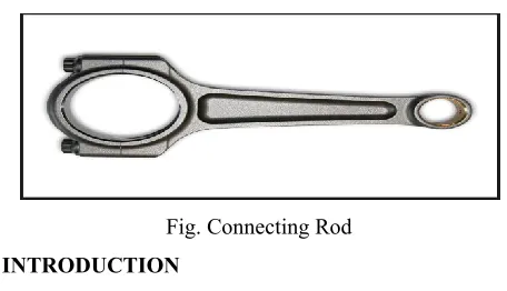
Fig. Connecting Rod INTRODUCTION
In a reciprocating position engine to the connecting rod or con rod connects the piston to the crank or crankshaft, alongside the crank they form a simple mechanism converts reciprocating motion into rotating motion.
Available online: https://edupediapublications.org/journals/index.php/IJR/ P a g e | 1039
As a connecting rod is rigid, might transmit either push or pull and then the rod might rotate each halves of a revolution i.e. Piston pushing and piston pulling. Earlier mechanisms used like chains, may solely pull in a very few two-stroke engines, the connecting rod is barely needed to push. Now days, connecting rods are best well-known through their use in a internal combustion piston engines like automotive engines. These are clearly different forms earlier types of the connecting rods utilized in stream engines and steam locomotives.
Fig: connecting rod with piston Importance of Con Rod In Engine
The connecting rod is that the main a part of the engine, additionally backbone of the engine. There is most significant of the connecting rod in an engine.
Fig: connecting rod in engine
Connecting rod rotates the crank shaft that helps the engine to maneuver on or any of the vehicles to rotate its wheels. It is designed to resist stresses from combustion and piston movement.
Connecting rods is toward lighter weight components. It should withstand with greater power loads though it is lower in weight. The main purpose of a connection rod is to provide fluid movement between pistons and a
crankshaft and therefore the connecting rod is beneath tremendous stress from the load represented by the piston. When building a high performance engine, great attention is paid to the connecting rods. The most effective feature of a connecting rod ought to be the uniform shape. The cross section of rod beam design ought to be spread and minimize stress load over massive uniformly shaped areas. In operation stress are generated and radiate from one or more source on a component because the rod functions.
Top dead centre (TDC) is the point at which the piston is closest to the cylinder head. Bottom dead centre (BDC) is the point at which the piston is farthest from the cylinder head. Displacement is the volume that a piston displaces in an engine when it travels from TDC to BDC during the same piston stroke.
Problem Statement
Connecting rod is one of the most critical components internal combustion. Connecting rod is connected in between the piston and crank shaft. While the crank shaft rotates piston moves from bottom dead centre to top dead centre vice versa. In this process connecting rod undergoes stress and deformation. Hence for the connecting rod when the load is applied, how the stresses and strain are induced in the component and deformation value, due to applied load are analysed.
Available online: https://edupediapublications.org/journals/index.php/IJR/ P a g e | 1040
weight and also performance of the engine. The structural factors considered for weight reduction during the optimization include the buckling load factor, stresses under the loads, bending stiffness, and axial stiffness. Thus, the component can give the higher strength, efficient design and lighter that would create a major success in the automotive and manufacturing industry. Among the main objectives are to improves the engine performance and also to strengthen the product that is ensure the safety of human being.
Connecting rod failed due to insufficient strength to hold the load. Increasing the strength, automatically it will longer the life cycles of the connecting rod. In this study, the design of the connecting rod will be modeled and at the same time increase the strength. And different materials are applied for gaining more stability. The study will be focus on the finite element modeling and analysis. From the analysis results, the decision whether connecting rod needs to change in material, load, design etc factors which induces stress in the component.
Objectives of project
The objectives of the project are as follows
(i) To develop structural modeling of connecting rod (ii) To perform fea of connecting rod
(iii) Suitable composite material study (iv) Study of load factors
(v) Study of stress, strain deformation induced in the connecting rod
(vi)To develop structural optimization model of connecting rod
Parts of connecting rod
Fig: parts of connecting rod
Crankpin end rod shank gudgeon pin end Types of Connecting Rods
Marine type Fixed centre design Fork and blade type Articular type COMPOSITE MATERIALS
Available online: https://edupediapublications.org/journals/index.php/IJR/ P a g e | 1041
desired position thereby transferring the external load to reinforcement. While the other constituent is reinforcement, can be either synthetic or natural fibers. The mechanical property mostly depends upon the shape and dimensions of reinforcement.
The most primary applications of composite materials are found where high strength and low weight are concerned. Few properties of composites accounted for their wider uses are high strength, low density, high tensile strength at high temperatures, high toughness, and high creep resistance. The matrix constitutes more than half of the volume fraction of the composite and fillers contribute less towards the volume but the change in properties is quite considerable. The variation over strength of composites lies with amount, distribution and type of filler material inclusion broadly.
THEORITICAL CALCULATIONS Pressure calculation:
Consider a 220cc engine, Engine type air cooled 4-stroke Bore × Stroke (mm) = 67×62.4 Displacement=220 cm3
Maximum Power = 20.8 Bhp at 8500rpm Maximum torque= 19.12 Nm at 7000rpm Mechanical efficiency of the engine (η) = 80 %.
P = 1.365MPa
Maximum Pressure, Pmax=10xP =10x1.365
=13.65Mpa
So approx 16mpa is taken as pressure applied on connecting rod
Design Calculation of connecting rod
Fig.: I Section for connecting rod From standards,
Thickness of flange and web of the sectio = t Width of the section B = 4t
Height of the section H = 5t Area of the section A = 11t2
Moment of inertia about x axis Ixx= 34.91t4 Moment of inertia about y axis Iyy= 10.91t4 Therefore Ixx/Iyy= 3.2
So, in the case of this section (assumed section) Proportions shown above will be satisfactory. Length of the connecting rod (L) = 2 times the stroke L = 124.8 mm
Fc= (πd2/4) * gas pressure
Fc= 48125.154 N
WB = FC × F. S.=48125.154 ×1.78 = 85662.77 N We know that radius of gyration of the section about X-axis,
Available online: https://edupediapublications.org/journals/index.php/IJR/ P a g e | 1042
Length of Connecting Rod = 2×stroke = 2×62.4
=124.8 mm
Equivalent length of the connecting rod for both Ends hinged, L= l = 124.8 mm
For generaly used aluminium alloy material Now according to Rankine‟s formula, we know that Buckling load (WB),
85662.77 = 7.35 mm (α = 0.002) Thus, the dime=
nsions of I-section of the Connecting rods are:
Thickness of flange and web of the section = t =7.35 mm
Width of the section, B = 4 t = 4 × 7.35 =29.4 mm Height of the section, H= 5 t = 5 × 7.35 = 36.75 mm Depth near the big end,
H1 = 1.2H = 1.2 × 36.75 = 44 mm and Depth near the small end,
H2 = 0.85H = 0.85 × 36.75 = 31.23 mm
For Aluminium 6061 SIC-15% composite material Now according to Rankine‟s formula, we know that Buckling load (WB),
85662.77=
= 5.254 mm
Width of the section, B = 4 t = 4 × 5.254=21.01 mm Height of the section, H= 5 t = 5 ×5.254= 26.27 mm Depth near the big end,
H1 = 1.2H = 1.2 × 26.27 = 31.52 mm Depth near the small end,
H2 = 0.85H = 0.85 × 26.27 = 22.32 mm
Introduction to Solidworks
Solid works is mechanical design automation software that takes advantage of the familiar Microsoft windows graphical user interface. It is an easy-to-learn tool which makes it possible for mechanical designers to quickly sketch ideas, experiment with features and dimensions, and produce models and detailed drawings
Design procedure of Connecting Rod
For designing the Connecting Rod the following procedure has to be follow
2d sketch of a connecting rod
Available online: https://edupediapublications.org/journals/index.php/IJR/ P a g e | 1043
Extrude cut it to 2mm
Make Holes
Draw a sketch on front plane for bolting holes
Mirror is used for making for symmetry on both sides
Fillet the edges for smooth surfacing
Different Views of Connecting Rods INTRODUCTION TO SIMULATION
Simulation is a design analysis system. Simulation provides simulation solutions for linear and nonlinear static, frequency, buckling, thermal, fatigue, pressure vessel, drop test, linear and nonlinear dynamic, and optimization analyses.
Fig: simulation example
FEM (Finite element method)
Available online: https://edupediapublications.org/journals/index.php/IJR/ P a g e | 1044
Static analyses
Static analysis deals with the conditions of equilibrium of the bodies acted upon by forces. A static analysis can be either linear or non-linear. All types of non-linearities are allowed such as large deformations, plasticity, creep, stress stiffening, contact elements etc.
modal analyses
When an elastic system free from external forces is disturbed from its equilibrium position it vibrates under the influence of inherent forces and is said to be in the state of free vibration. It will vibrate at its natural frequency and its amplitude will gradually become smaller with time due to energy being dissipated by motion. The main parameters of interest in free vibration are natural frequency and the amplitude.
Fig: structural analysis Materials and their properties
• Fixed support
• Load
Load at 16 MPA
Meshing
Mesh Type: Tetrahedral No. of nodes: 16190 No. of elements: 8821
STRUCTRUAL ANALYSIS RESULTS Material: 42CrMo4 (steel alloy)
Maximum stress
Available online: https://edupediapublications.org/journals/index.php/IJR/ P a g e | 1045
Maximum strain
Material: Al6061+B4C (Aluminium alloy+5% boron carbide)
Maximum stress
Total deformation
Maximum strain
Material: Aluminium Silicon Magnesium Alloy
Maximum stress
Total deformation
Maximum strain
Material: Aluminium Silicon Carbide Maximum stress
Available online: https://edupediapublications.org/journals/index.php/IJR/ P a g e | 1046
Maximum strain
MODEL ANALYSIS:
Modal analysis has performed on six different mode Material: 42CrMo4 (steel alloy)
Mode1
Mode2
Mode3
Mode4
Mode5
Mode6
Material: (Aluminium alloy+5% boron carbide) Mode1
Available online: https://edupediapublications.org/journals/index.php/IJR/ P a g e | 1047
Mode3
Mode4
Mode5
Mode6
Material: Aluminium Silicon Magnesium Alloy Mode1
Mode2
Mode3
Available online: https://edupediapublications.org/journals/index.php/IJR/ P a g e | 1048
Mode5
Mode6
Material: Aluminium Silicon Carbide Mode1
Mode2
Mode3
Mode4
Mode5
Available online: https://edupediapublications.org/journals/index.php/IJR/ P a g e | 1049
RESULTS AND DISCUSSION:
Modeling of the connecting rod has done by using solid works 2016 premium software package. And therefore the model is saved in initial graphics exchange specification (iges) and is imported into the ansys work bench to perform static structural analysis and modal analysis. The results of the analysis have shown below.
Static Structural analysis Table: Static analysis
Table: Model Analysis –I
Model Analysis
Table: Model Analysis –II
CONCLUSION
Available online: https://edupediapublications.org/journals/index.php/IJR/ P a g e | 1050
can conclude that Aluminium Boron Carbide (Al+B4C) is the best composite materail for connecting rod , due to its high weight to strenth ratio and dynamic behaviour and economically too.
REFERENCES
Abhinav gutam et al. “static stress analysis of connecting rod using finite element approach”. Isor journal of mechanical and civil engineering, volume 10, issue 1(nov – dec. 2013), pp 47-51.
Ram bansal et al.”Dynamic simulation of a connecting rod made of aluminium alloy using finite element analysis approach”. Isor journal of mechanical and civil engineering, volume 5, issue 2 (jan – feb. 2013), pp 01-05.
Kuldeep b et al. ”analysis and optimization of connecting rod using alfasic composites”. Journal of ijirset, vol. 2, issue 6, june 2013.
Pravardhan s. Shenoy et al. “dynamic load analysis and optimization of connecting rod”. In his thesis.
Gvss sharma and p.srinivas rao”process capability improvement of an engine connecting rod machining process.”
K. Sudershn kumar, dr. K. Tirupathi reddy, syed altaf hussain, „modeling and analysis of two wheeler connecting rod‟international journal of modern engineering research vol -2, issue-5, pp-3367-3371,sep-oct 2012
Suraj pal, sunil kumar,”design evaluation and optimization of connecting rod paramaters using fem” international journal of engineering and management research vol -2 ,issue-6,dec 2012.
Vivek c. Pathade ,bhumeshwar patle ,ajay n.ingale “stress analysis of ic engines connecting
rod by fem “international journal of engineering and innovative technology, vol-1,issue-3,march 2012
Priyank d. Toliya, ravi c. Trivedi, prof. Nikhil j. Chotai,”design and finate element analysis of aluminium-6351 connecting rod international journal of engineering and management research and technology vol-2,issue 5 may 2013
S.shaari, m.m. rahman, m.m. noor, k. Kadirgama and a.k. amirruddin “design of connecting rod of internal combustion engine: a topology optimization approachm”. National conference in mechanical engineering research and post graduate studies( 2nd ncmer 2010) 3-4 dec 2010, pp 155-166.