An Precise Frequency Tracking Technique Based on Short
Current Detection
Mahesh Thati
& Mahesh Jonnala
1Assistant Professor, Dept of EEE, Institute of Aeronautical Engineering college, Dundigal, Hyderabad.
E-mail:[email protected]
2Masters in Power Electronic Systems from Osmania University, Hyderabad.
E-mail:[email protected] ABSTRACT:This paper suggests a short current control
method to eradicate the short current by regulating the switchingfrequency to method the inherent frequency. When systemrunning in force resonant mode, there will exist dangerousshort current between the resonant network and the switchingnetwork when switching frequency drifts away from inherentfrequency of the resonant network.Inductive Power Transfer (IPT) systems for transmitting tens to hundreds of watts have been reported for almost a decade. Most of the work has concentrated on the optimization of the link efficiency and have not taken into account the efficiency of the driver. A novel frequency tracking method based on short current detection is proposed for IPT applications. In addition, an instantaneous short current detection method utilizing cheap comparator is proposed. Furthermore, a fast and accurate tracking method is proposed to calculate the frequency mismatch and make a correction. The method can realize accurate frequency correction in several oscillation periods.
KEYWORDS-Electromagnetic coupling, frequency
control, inductive power transfer (IPT).
I. INTRODUCTION
Inductive power transfer (IPT) technology realizes efficientenergy transfer across large air gap from power
supply to electricalequipment. With its rapid
development, more and moreapplications have been emerging in recent years such as mobilephone, electrical vehicle material handling, and biomedicalimplants. For a typical IPT system, resonant tanks are verycommonly used to produce low-distortion sinusoidal oscillationand increase the system reactive capability. However, the inherentparameters of the resonant tanks may dynamically drift away fromthe designed parameters due to load variation and mutualcoefficient change. It is because the
mutual coupling between theprimary and secondary sides will produce dynamical reflectionimpedance in the primary resonant tank and cause its inherentfrequency drifting. In order to realize soft switching, the topologyswitching signal must keep up with the inherent frequencyvariation. It should be noted here that the inherent frequency refersto the inherent soft switching frequency of the primary inverter,which transforms dc input to high-frequency ac output. Typicalfrequency tracking method is a passive tracking method, whichcompletes topology switching by detecting the zero crossing pointsof resonant variables. This method is efficient to produce a selfsustained oscillation. However, it normally requires start-upcontrol to produce initial oscillation, and the oscillation may fail inthe low-quality-factor condition. Most important of all, this methodcannot realize accurate frequency tracking. There inevitably existsa short-time lag in the topology switching due to the time delayand disturbance on gate driver and detection circuit in the feedbackloop. The switching time lag will result in resonant waveformdistortion and augment of switching loss. In particular, accordingto the first wireless power standard “Qi” the oscillation frequencyin commercial IPT product should be set in the frequency rangefrom 110 to 205 kHz. In the high-frequency range, the systembecomes more complex and sensitive because many parasiteparameters will affect system performance. A tiny time delay ordisturbance in the feedback path may cause the systemperformance to fall drastically. However, due to the inherentlypassive running property, it is impossible to eliminate theswitching time lag and disturbance so that the frequency trackingerror will always exist. Compared with the passive trackingmethod,
an active tracking method which completes
the tracking accuracy and speed. Since the inherent frequency isdetermined by an implicit high-order differential equation set, it isdifficult to obtain its accurate value. Furthermore, even if theinherent frequency can be calculated, the time consuming will beunaffordable for real-time tracking. Therefore, instead of thecomplex calculation, a simple and real-time tracking method withunknown inherent frequency is needed. In the IPT system, itswellknown that the short current is adverse which should be avoided.The short current occurs when resonant tank is shorted by theswitching network. It is caused by mismatch between the drivingfrequency and the inherent soft switching frequency of theresonant tank. A large mismatch can produce dangerous highcurrent which may cause the switching devices to fail. It has beenfound that the short current occurs almost instantaneously whilethe mismatch appears. Therefore, it can be utilized as a fast andaccurate ruler to measure the frequency error.
A basic IPT systems architecture consistsof several modules, as illustrated in Fig. 1. The architectureincludes dc power supply units (PSUs), coil driver (i.e. clockgenerator and power amplifier (PA) having an impedancematching network), transmitting (TX) coil with separationdistance D from a receiving (RX) coil (measured from thecentre-to-centre of the coils), an optional rectifier/regulator anda load. To fully characterize the complete system, the end-toend efficiency ηee of all the building blocks, from the ac sourceto the load, can be considered as follows; where the efficiencyterms are shown on Fig. 1
Fig. 1. Inductive power transfer systems architecture
For a typical IPT system, resonant tanks are very commonlyused to produce low-distortion sinusoidal oscillation and increase the system reactive capability. However, the inherentparameters of the resonant tanks may dynamically drift awayfrom the designed parameters due to load variation and mutualcoefficient change [10], [11]. It is because the mutual coupling between the primary and secondary sides will producedynamical reflection impedance in the primary resonant tankand cause its inherent frequency drifting. In order to realizesoft switching, the topology switching signal must keep upwith the inherent frequency variation. It should be noted herethat the inherent frequency refers to the inherent soft switchingfrequency of the primary inverter, which transforms dc input tohigh-frequency ac output. Typical frequency tracking method isa passive tracking method, which completes topology switchingby detecting the zero crossing points of resonant variables[12]–[15]. This method is efficient to produce a self-sustainedoscillation.
II. THEORY AND METHODOLOGY
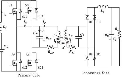
In terms of structures of resonant network at primary side,there are normally two types. One is parallel resonant, and theother is series resonant. The short current typically appearsin parallel resonant structure. A typical parallel-resonant-typeICPT system is shown in Fig. 2
1) At the primary side, the dc input Edcand filter
compose a quasicurrent source.
2) In addition, the switching network consists of two switch pairs (S1, S4) and (S2, S3) and their inherent inverse parallel diodes (SD1–SD4). 3) The two switch pairs operate complementarily
at the forced switching frequency, transform dc current input to high-frequency square-wave current, and
4) Inject it into the resonant network, which is composed of resonantinductor LP , capacitor CP ,
and equivalent series resistance (ESR) resistance RLP .
The resonant network converts the square-wave current to sinusoidal current for primary coil to produce alternating magnetic field.
1) At the secondary side, the secondary coil will pick up energy from the magnetic field and produce resonance in the parallel resonant network composed of resonant inductor LS and
capacitor CS.
2) With the rectifier and filter network (Lf ,Cf), ac
energy is transformed to dc output to the load (RL).
3) While the forced switching frequency is
approaching the inherent soft switching frequency of the primary resonant network, the switching points will be close to the zero crossing points of the resonant voltage uCPwhich
can producezero-voltage-switching conditions.
In system running, when the switching frequency drifts awayfrom the inherent frequency, there are two possible cases. Oneis higher, and the other is lower than the inherent frequency. Thetwo cases are quite different in nature and should be analyzed,respectively.
A. Higher Case
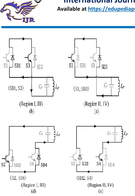
As it can be seen from (a), the waveforms from up to downare resonant capacitor voltage uCP, switching signal S, andthe input current iac of the resonant tank, respectively. For theswitching frequency is higher than the inherent frequency,the switching instants will appear before the zero switchingpoints of uCP. In addition, the mismatches will produce fourshort current regions
(Region I–IV). In each region, the shortcurrent has different path and can be illustrated from (b) to(e), respectively.
a) In Regions I and III, the switch pair (S1, S4) turns on and the switch pair (S2, S3) turns off. However, as the resonant voltage uCP is below
zero, two short current loops will form in the inverter bridge.
b) The one shown in (b) is the upper short current
loop including S1 and SD3.
c) The other shown in (d) is the lower loop include
SD2 and S4.
d) In Regions II and IV, the switch pair (S1,S4) turn on and (S2, S3) turn off. However, the resonant voltage uCP is above zero.
e) Similarly, there are two short current loops. The
one shown in (c) is the upper one including SD1 and S3, and the other shown in (e) is the lower one including S2 and SD4.
Fig. 3.Switching frequency lower case. (a) Operating waveforms when shortcurrent occurs. (b) (Regions I and
III) Upper short current loop. (c) (Regions IIand IV) Upper short current loop. (d) (Regions I and III) Lower
short currentloop. (e) (Regions II and IV) Lower short current loop.
B. Lower Case
When the switching frequency is lower than inherent frequency, the short current will appear as well. However, it isdifferent from the higher case in nature. The lower case canbe illustrated in Fig. 3.As it can be seen from (a), since the switching frequency islower than the inherent frequency, the switching instants willlag behind the zero crossing points of uCP.
a) Furthermore, the mismatches will produce four short current regions (Regions I–IV).
b) In Regions I and III, when the resonant voltage uCP crossing the zero, the switching pair (S2, S3) still maintains ON STATE because the switching signal is lagged behind.
c) Two short current loops will form in the upper and lower bridges, respectively. The one
including SD1 and S3 is shown in (b), and the other including S2 and SD4 is shown in (d). d) In Regions II and IV, the switch pair (S1, S4)
will maintain ON STATE. Similarly, the upper short current loop including S1 and SD3 is shown in (c), and the lower one including SD2 and S4 is shown in (e).
e) However, it should be noted that the short
current is driven by resonant inductor LP instead of capacitor CP as the resonant voltage is
clamped to zero.
f) Therefore, the short current peak of input current iac shown in (a) is much lower than that of the higher case.
g) In addition, in higher case, the short current appears at the front end of the switching signal, while in the lower case, it appears at the back end.
III. SHORT CURRENT ANALYSIS
Since the principles of the short current are quite different inthe higher and lower cases, the short current analysis should begiven, respectively.
A. Higher Case
According to the analysis of the Section III, the equivalentcircuit of the short current loop can be shown in Fig. 4.
Fig. 4. Equivalent circuit of short current loop.
As can be seen, the short current is iC, and resistance RCis
the sum of conducting resistances of switch devices anddiodes on the short current loop. Moreover, the resistance RPis the sum of ESR resistance RLP and
B. Lower Case
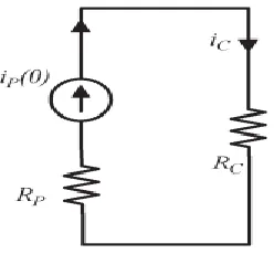
In the lower case, the resonant voltage is clamped to zeroand cannot drive the short current. The short current is actually the freewheeling current of the resonant inductor LP .
The equivalent circuit of the short current loop can be shownin Fig. 5.In the short-time interval of the short current, the resonantcurrent iP can be seen as a constant,
which equals the instantdetection circuit.current iP (0)
when the short current occurs.
Fig. 5. Equivalent circuit of short current loop.
IV. FREQUENCY TRACKING CONTROLS
The frequency tracking control is to make the switchingfrequency accurately and rapidly keep up with the inherentfrequency variation of the resonant tank.
A. Short Current Detection
However, as the duration time of the short current is normallyless than 1 μs, it is quite difficult for normal analog to digitalchip to detect it. In this paper, a short current detection circuitusing normal comparator chip LM319 is designed. It can beshown in Fig. 6.
Fig. 6. Short current detection circuit. As can be seen, a comparator L1 is used to detect the duration time TC of the short current. As analyzed in Section III, two identical short currents will form in the upperand lower bridges simultaneously in no matter the higher orthe lower case. Moreover, in the upper bridge, the two shortcurrent loops should include (SD1, S3) and (S1, SD3) in nomatter the higher or the lower case.
It can be seen that theshort current in any diode of SD1– SD4 will be identical. Inorder to simplify the detection circuit, only SD1 is selected todetect the short current. However, as the inherent diode SD1is normally embedded in switch device, it is difficult to detectthe current on it. Therefore, an inverse parallel diode recoverydiode (RD) with low conduction resistance is added to replaceit. In addition, a block diode is put in series with the switchS1 to invalidate the diode SD1. Furthermore, with a currenttransformer, the short current on RD can be detected.
B. Determining the Mismatch Direction
The second step of tracking is to determine whether thefrequency is higher or lower than the inherent frequency. Ascan be seen from Figs. 2 and 3, the short current on SD1 willselect different occurrence regions for the higher or lower case.For higher case, the short current will select Regions II and IVfor occurrence, and for the lower case, the short current willselect Regions I and III.
C. Mismatching Calculation and Correction
The third step of tracking is to calculate the deviation between the switching frequency and the inherent frequency.
Thetracking method should be different according to the higher andlower cases. For the higher case, the frequency mismatchingcalculation method can be illustrated in Fig. 7.
V. SIMULATION RESULTS
A practical investigational IPT system has been built to verifythe proposed tracking method which exploits an FPGA chip asthe tracking controller. The experimental system structure.
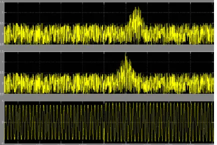
Fig. 8. Waveforms of the system start proces
Fig. 9. Waveforms of load change from R2 to R1 (from light toheavy load conditions).
Fig. 10. Waveforms of load change from R1 to R2 (from heavy tolight load conditions)
VI. CONCLUSION
In this paper, a new accurate frequency tracking methodbased on short current detection has been proposed for anIPT system. An instantaneous short current detection methodutilizing cheap comparator is proposed. Furthermore, a fast andaccurate method is proposed to calculate the frequency mismatch and make a correction. Compared with the conventionalautonomous oscillation method, this method is an active onewhich can overcome the common problems such as feedbackdelay, resonant failure, and additional start-up circuit.
REFERENCES
[1] M. Budhia, V. Vyatkin, and G. A. Covic, ”Powering flexible manufacturing systems with intelligent contact-less power transfer,” in 6th IEEEInternational Conference on Industrial Informatics, pp. 1160-1165, 2008.
[2] S. Y. R. Hui and W. W. C. Ho, ”A new generation of universalcontactless Battery Charging platform for portable Consumer Electronicequipment,” IEEE Trans. on Power Electron., Vol. 20, pp. 620-627, 2005.
[4] Y. Wu, L. Yan, and S. Xu, ”A new contactless power delivery system,”in 6th International Conference on Electrical Machines and Systems, pp.253-256, 2003.
[5] L. Zhao, C. F. Foo, K. J. Tseng, and W. K. Chan, ”Transcutaneoustransformers in power supply system for an artificial heart,” in International Conference on Power Electronic Drives and Energy Systems forIndustrial Growth, pp. 348-352,1998.
[10] J. U. W. Hsu, A. P. Hu, and A. Swain, “Fuzzy logic-based directional fullrange tuning control of wireless power pickups,” IET Power Electron.,vol. 5, no. 6, pp. 773–781, Jul. 2012.
[11] J. U. W. Hsu, A. P. Hu, and A. Swain, “A wireless power pickup basedon directional tuning control of magnetic amplifier,” IEEE Trans. Ind.Electron., vol. 56, no. 7, pp. 2771–2781, Jul. 2009.
[12] B. Sharp and H. Wu, “Asymmetrical voltage-cancellation control for LCLresonant converters in inductive power transfer systems,” in Proc. IEEEAppl. Power Electron. Conf. Expo., Orlando, FL, USA, Feb. 5– 9, 2012,pp. 661–666.
[13] W. Yanzhen, A. P. Hu, D. Budgett, S. C. Malpas, and T. Dissanayake,“Efficient power-transfer capability analysis of the TET system using theequivalent small parameter method,” IEEE Trans. Biomed. Circuits Syst.,vol. 5, no. 3, pp. 272–282, Jun. 2011.
[14] T. D. Dissanayake, A. P. Hu, S. Malpas, L. Bennet, A. Taberner, L. Booth,and D. Budgett, “Experimental study of a TET system for implantablebiomedical devices,” IEEE Trans. Biomed. Circuits Syst., vol. 3, no. 6,pp. 370–378, Dec. 2009.
[15] S. Ping, A. P. Hu, S. Malpas, and D. Budgett, “A frequency controlmethod for regulating wireless power to implantable devices,” IEEETrans. Biomed. Circuits Syst., vol. 2, no. 1, pp. 22–29, Mar. 2008
BIODATA
Mahesh Thati, a teaching experience of 6 years i.e. from 2012 to 2017 and currently Working as Assistant Professor in Institute of Aeronautical Engineering college, Dundigal, Hyderabad.