Study on Attitude Control Method for Zero-Doppler Steering
in Space Borne SAR System
Xinqiang Zhao1 and Dan Wei2, *
Abstract—For the spaceborne synthetic aperture radar (SAR) system, in order to alleviate the complexity of the imaging algorithm and to improve the accuracy of the applications of SAR images, attitude steering is required to reduce the Doppler centroid to 0 Hz. In published literature, two-dimensional attitude steering, including yaw and pitch steering, is employed for elliptic orbiting SAR systems. This paper proposes a new steering approach involving only yaw steering to suppress the Doppler centroid of the mid-range to theoretically 0 Hz with a low residual Doppler centroid at the edge of the range extent. This may reduce the complexity of the attitude control system. The comparison of the performances of the current applied methods and the proposed approach is carried out with a simulation, and the effectiveness of the new approach is validated by the results.
1. INTRODUCTION
In spaceborne synthetic aperture radar (SAR) systems, the Doppler centroid is not zero in the conventional broadside mode with zero beam attitudes due to the earth rotation and eccentricity of the orbit [1, 2]. The large Doppler centroid may result in serious coupling of range and azimuth variables and increasing the difficulty of focusing. This may also result in degradation in image registration accuracy, interferometry accuracy, scalloping correction performance for ScanSAR processing and other factors [2, 3]. In order to suppress the Doppler centroid to 0 Hz, attitude steering method is applied to point the antenna beam centerline in the direction of Doppler zero-line. The effectiveness of the attitude steering methods has been validated in advanced space borne SAR systems including TerraSAR-X [4, 5], to name a few.
Several attitude steering policies can be found in current literature. Ref. [1] proposes a yaw steering method which works perfectly for circular orbiting space borne SAR systems, but this method does not work well in elliptic orbit cases, which will generate a Doppler frequency at the scale of hundreds of Hz. Refs. [6, 7] and [8] proposes a Total Zero Doppler Steering (TZDS) method by exploiting an additional pitch steering. This method is applied in the TerraSAR-X system and suppresses the Doppler centroid to tens of Hz all over the range swath [9, 10]. However, this method suppresses the Doppler centroid at the cost of increasing the complexity of the SAR system since it requires attitude steering on two dimensions. Besides, in some SAR systems, there are always some constraints on the attitude of the satellite for specific purpose [11, 12], which also sets a limit on the applications of the 2-dimensional attitude steering method.
By analyzing the aforementioned attitude steering methods for elliptic orbiting SAR systems, it can be found that the pitch steering angle is usually very small in nearly circular orbit cases. This implies that an attitude steering method with only yaw steering may suffice to suppress the Doppler centroid to 0 Hz for the mid-range at the cost of causing a low residual Doppler centroid at the edge of the range extent. It can reduce the complexity of the attitude control system while not affecting
Received 21 June 2016, Accepted 24 October 2016, Scheduled 11 November 2016 * Corresponding author: Dan Wei ([email protected]).
the accuracy of the SAR products. This paper studies the attitude steering problem and proposes a new method to calculate the yaw steering angle with zero pitch steering angle or with a given pitch steering angle. The former formula can be used to perform 1-D yaw steering in the SAR systems with one coordinate axis pointing toward the earth center [6, 7]; the latter can be used to perform 1-D yaw steering in the SAR systems with one coordinate axis pointing perpendicular to the earth surface [5] or to refine the performance of TZDS.
This paper is organized as follows. Section 2 derives the formula for calculating the yaw steering angle of the new method. Section 3 gives the simulation results to compare the performances of the new method and the currently applied methods. Section 4 gives a discussion and draws the conclusion.
2. THE GENERAL METHOD FOR ZERO DOPPLER STEERING
2.1. Geometry for SAR Attitude Steering
The Doppler frequencyfdop of a point target is given by [13]
fdop=−
2
λ
(RS−RT)·(R˙S− R˙T)
R (1)
whereλis the wavelength; RS and RT are the position vectors of satellite and target, respectively; R˙S and R˙T are the corresponding first order derivatives; R is the range distance from the satellite to the target; ·is the inner product operator.
Let fdop equal 0. Expanding the terms in the brackets, substituting the relation RT · R˙T = 0 for
earth rotation, and shifting the term irrelevant to the target to the other side yield
RS·R˙T + R˙S·RT = RS· R˙S. (2) From the derivation process, it may be contended that Eq. (2) is the function for zero-Doppler plane. To get a concrete point of this contention, we proceed to derive an algebraic form of Eq. (2) in terms of coordinates.
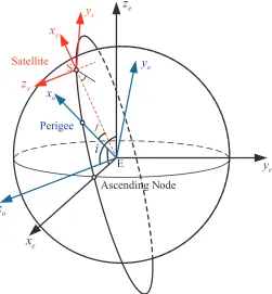
First, three coordinate systems depicted in Figure 1 are defined as follows.
(1) Earth centered coordinate system E −xeyeze: The origin coincides with the Earth center, and the ze-axis is along the angular momentum direction of the Earth; the xe-axis is pointing to the ascending node of the orbit, while the ye-axis is directed to complete a right-handed Cartesian system. (2) Orbit plane coordinate systemE−xoyozo: The origin coincides with the Earth center, while its
zo-axis is along the angular momentum direction of the satellite; the xo-axis is pointing to the perigee, while the yo-axis is directed to complete a right-handed Cartesian system.
(3) Satellite local coordinate systemS−xsyszs: The origin coincides with the satellite mass center, while itszs-axis is along the angular momentum direction of the satellite; thexs-axis is pointing to the satellite away from the earth center, while the ys-axis is directed to complete a right-handed Cartesian system.
Then the translations between these three coordinate systems are as following: (1) FromE−xoyozo to E−xeyeze
E−xoyozo needs to be rotated aboutzo-axis by ω, where ω is the argument of perigee, and then be rotated about the x-axis byi, whereiis the inclination, so the rotation matrix from the orbit plane coordinate system E−xoyozo to the earth centered coordinate system E−xeyeze is
Aeo=
1 0 0
0 cosi −sini 0 sini cosi
cosω −sinω 0 sinω cosω 0
0 0 1
. (3)
(2) FromS−xsyszs to E−xoyozo
S−xsyszs needs to be translated by −→SE and then be rotated about zo-axis by f, where f is the true anomaly. The rotation matrix is
Aos =
cosf −sinf 0
sinf cosf 0
0 0 1
i
Perigee
Ascending Node Satellite
f
e
x
e y
e
z
o
x s
z
s
y
o
y s
x
o
z
Figure 1. Geometry of space borne SAR.
2.2. Derivation of Steering Angles for SAR Attitude Control
In the orbit plane coordinate system E −xoyozo, we have the satellite position vector RS , and its derivative R˙S is
R
S = a(1−e
2)
1 +ecosf [cosf, sinf, 0]
T
˙
RS =
μ
a(1−e2)[−sinf, cosf +e, 0] T.
(5)
whereais the semi-major axis length, ethe eccentricity, and μthe earth gravitational constant In the earth centered coordinate system E−xeyeze, the position vector of the target RT and its first order derivative R˙T can be expressed as
RT =
x
T
yT
zT
, R˙T =ωe
−y
T
xT 0
=ωe
0 −1 0
1 0 0 0 0 0
xT
yT
zT
. (6)
whereωe is the angular velocity of the Earth. Denoting that
Ac =
0 −1 0
1 0 0 0 0 0
. (7)
using the relations that RS=AeoRSand R˙S =AeoR˙S, replacing the inner product of two vectors by the corresponding matrix multiplication, and substituting Eqs. (5) and (6) into Eq. (2), a plane equation with respect to RT drops out as
RS· R˙S =
ωeRSTATeoAc+ R˙ T S ATeo
of which the normal vector is
n=
ωeRSTATeoAc+R˙ T S ATeo
T
. (9)
InS−xsyszs, without attitude steering, the unit vector of the beam center line can be expressed as
l= [−cosγ, 0, εsinγ]T. (10) whereεis an indicator variable that describes radar’s looking to the right (−1) or left (+1) of the orbital velocity vector.
Assume that the angles for yaw and pitch steering areθp and θy, respectively, then the coordinate of the beam center line vector in S−xsyszs becomesl =Asal, where the rotation matrix Asa is
Asa=
1 0 0
0 cosθy −sinθy 0 sinθy cosθy
cosθp −sinθp 0 sinθp cosθp 0
0 0 1
. (11)
Converted into E−xeyeze, the coordinate ofl isl =AeoAosAsal.
For zero Doppler steering, the beam center line must be in the zero Doppler plane, hencel should be perpendicular ton, which can be written as
n·l =ω
eRSTATeoAc+ R˙ T S ATeo
AeoAosAsal=
ωeRSTATeoAcAeo+ R˙ T S
AosAsal= 0. (12)
The last simplification employs the relation thatA−eo1 =ATeo. (1) 2-D steering
Observe that the second dimension oflis 0, so AosAsalcan be viewed as a linear combination of the first and third column vectors ofAosAsa. In order to satisfy Eq. (12), it is sufficient to have
ωeRSTATeoAcAeo+ R˙ T S
col1(AosAsa) = 0
ωeRSTATeoAcAeo+ R˙ T S
col3(AosAsa) = 0
. (13)
where coli(·) denotes the ith column of the matrix in the brackets. Since col3(AosAsa) relates only to
the yaw steering angle θy, the second equation of Equation (13) can be solved for θy, then θp can be determined from the first equation by using θy. For convenience of reference, the steering angles are listed here asθyo and θpo.
θyo= tan−1
k1sinicos(ω+f)
k2(1 +ecosf)−k1cosi
θpo=ktan−1
⎛
⎝ ek2sinf
[k1sinicos(ω+f)]2+ [k2(1 +ecosf)−k1cosi]2 ⎞
⎠. (14)
where
k1 =ωe a
(1−e2)
1 +ecosf, k2 =
μ
a(1−e2), k=
−1 k2(1 +ecosf)−k1cosi≥0
1 k2(1 +ecosf)−k1cosi <0 . (15)
(2) 1-D yaw steering with zero pitch steering angle
Let θp = 0 in Eq. (12), by collecting together the terms related to sinθy and cosθy, respectively, we have
[k1cosi−k2(e+ cosf)] sinθy + [k1sinicos(ω+f)] cosθy =εek2sinfcotγ. (16)
Employing the triangular identity sinθycosθ+ cosθysinθ= sin(θy+θ) yields
whereθyo and θpoare written as in Eq. (14).
(3) 1-D yaw steering with a given pitch steering angle
Given a pitch steering angleθp, the yaw steering angle can be solved as
θy = sin−1
⎡
⎣εtanθpocotγcosθp 1 + sin2θpcot2γ
⎤
⎦+θyo−θ. (18)
where
θ= tan−1(εsinθpcotγ). (19)
3. SIMULATION RESULTS
For the convenience of reference, the analytical form of the steering law employed by TerraSAR-X is listed here:
θy= tan−1
sinicos(ω+f)
N−cosi
, θp=kcos−1
1 +ecosf
1 +e2+ 2ecosf
, k=
1 0≤f < π
−1 π ≤f <2π . (20)
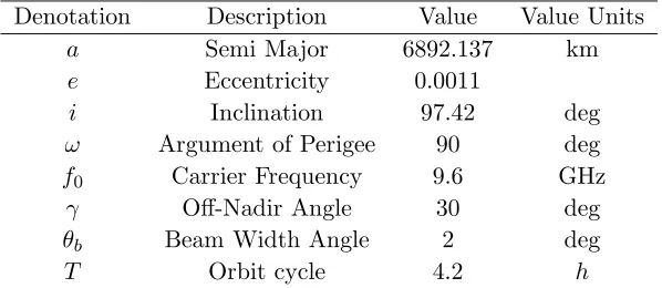
where N is the number of revolutions per day. There is a little improvement on the accuracy of this steering law by replacingN withωs/ωe, whereωs is the instantaneous angular velocity of satellite. We label the steering law that TerraSAR-X employs and its improvement edition as TZDS and TZDM, respectively, label the steering law in Eq. (17) as OLY and the steering law in Eq. (18) with a given pitch angle as OLYT. The parameters used in the simulation are listed in Table 1. The orbit is a kind of low sun synchronous orbits which most current SAR systems adopt. The beam width angle offers a range swath of 30 kilometers.
Table 1. Orbit elements and SAR system parameters for simulation.
Denotation Description Value Value Units
a Semi Major 6892.137 km
e Eccentricity 0.0011
i Inclination 97.42 deg
ω Argument of Perigee 90 deg
f0 Carrier Frequency 9.6 GHz
γ Off-Nadir Angle 30 deg
θb Beam Width Angle 2 deg
T Orbit cycle 4.2 h
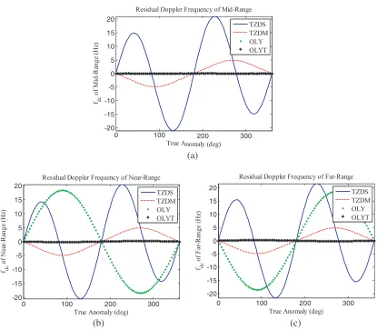
The yaw and pitch steering angles that the above methods employ and the residual Doppler centroid at the mid-range and at the edge of the range extent are demonstrated in Figure 2. The scales of the residual Doppler frequency are tabulated in Table 2. Based on the simulation results, it can be concluded that:
(1) For the mid-range, the Doppler centroid is reduced to 0 Hz by employing OLY and OLYT, while there is a small residue by employing TZDS and TZDM.
(2) Compared with the residual Doppler frequency over the range extent by employing TZDS and TZDM, there is a variation of±20 Hz of the residual Doppler centroid. This low variation will not add the difficulty of focusing due to the azimuth over sampling.
(3) The residual Doppler centroid can be reduced from ±20 Hz by employing TZDS to ±5 Hz by employing TZDM. The residual Doppler centroid can be reduced further to almost 0 Hz by employing the yaw steering angle of OLYT.
0 100 200 300 -20
-15 -10 -5 0 5 10 15 20
Residual Doppler Frequency of Mid-Range
True Anomaly (deg) fdc
o
f M
id
-R
an
g
e (H
z)
TZDS TZDM OLY OLYT
0 100 200 300
-20 -15 -10 -5 0 5 10 15 20
Residual Doppler Frequency of Near-Range
True Anomaly (deg) fdc
o
f N
ea
r-R
an
g
e (
H
z)
TZDS TZDM OLY OLYT
0 100 200 300
-20 -15 -10 -5 0 5 10 15 20
Residual Doppler Frequency of Far-Range
True Anomaly (deg) fdc
o
f F
ar-R
an
g
e (H
z)
TZDS TZDM OLY OLYT
(a)
(b) (c)
Figure 2. Residual Doppler centroid over the range by employing different steering laws. (a) Residual doppler at mid-range. (b) Residual doppler at near-range. (c) Residual doppler at far-range.
Table 2. The scale of the residual doppler frequency.
TZD TZDM OLY OLYT
Mid-Range ±21.0 Hz ∼0 Hz ∼0 Hz ∼0 Hz Near-Range ±20.5 Hz ±4.9 Hz ±18.4 Hz ±0.2 Hz
Far-Range ±21.5 Hz ±4.9 Hz ±18.4 Hz ±0.2 Hz
and the residual Doopler centroid at the edge of range extent is low and will not cause defocus. Secondly, the system complexity is lower with only yaw steering than 2D altitude steering. Thirdly, the proposed algorithm can be applied in circular and elliptic orbit cases.
4. CONCLUSION
REFERENCES
1. Raney, R. K., “Doppler properties of radars in circular orbits,” International Journal of Remote Sensing, Vol. 7, 1153–1162, 1986.
2. Cumming, I. G. and F. H. C. Wong, Digital Processing Of Synthetic Aperture Radar Data: Algorithms and Implementation, Artech House, 2005.
3. Runge, H., “Benefits of antenna yaw steering for SAR,” IGARSS’91, 257–261, 1991.
4. Just, D. and B. Schattler, “Doppler-characteristics of the ERS-1 yaw steering mode,”International
Geoscience and Remote Sensing Symposium, 1992, IGARSS’92, 1349–1352, 1992.
5. Fiedler, H., E. Boerner, J. Mittermayer, and G. Krieger, “Total zero doppler steering — A new method for minimizing the doppler centroid,”IEEE Geoscience and Remote Sensing Letters, Vol. 2, 141–145, 2005.
6. Yu, Z., Y. Zhou, J. Chen, et al., “A new satellite attitude steering approach for zero Doppler centroid,” IET International Radar Conference 2009, 593–593, 2009.
7. Long, T., X. Dong, C. Hu, and T. Zeng, “A new method of zero-doppler centroid control in GEO SAR,”IEEE Geoscience and Remote Sensing Letters, Vol. 8, 512–516, 2011.
8. Scharf, D. P., “Analytic Yaw&-Pitch steering for side-looking SAR with numerical roll algorithm for incidence angle,” IEEE Transactions on Geoscience and Remote Sensing, Vol. 50, 3587–3594, 2012.
9. Fiedler, H., E. Boerner, J. Mittermayer, and G. Krieger, “Total zero doppler steering — A new method for minimizing the doppler centroid,”IEEE Geoscience and Remote Sensing Letters, Vol. 2, 141–145, 2005.
10. Fiedler, H., T. Fritz, and R. Kahle, “Verification of the total zero Doppler steering,” 2008 International Conference on Radar, 340–342, 2008.
11. Elkoteshy, Y., Y. Shuyuan, and F. Abdelkader, “Attitude error cancellation for strip-map SAR by controlling steering angles of the antenna platform,” 2014 11th International Conference on Electrical Engineering/Electronics, Computer, Telecommunications and Information Technology (ECTI-CON), 1–6, 2014.
12. Morabito, A. F., T. Isernia, and D. L. Di, “Optimal synthesis of phase-only reconfigurable linear sparse arrays having uniform-amplitude excitations,”Progress In Electromagnetics Research, Vol. 124, 405–423, 2012.