334 East Kelso Street Inglewood, California, 9030.1
ARPAS/DDT
;qYMSHARE, INC. " 745 Distel Drive los""Altos, California 94022
. . , . "
..
, .. "AReAs,:;, '.'
'R'efer~~~e 'lVi~nu~I'
DDT Reference Manual
,-"DDT COMMAN
ti '
·a.~"<;.<.'-.,.,, ..SUMMARY."
464 Hudson Terrace Englewood Cliffs, New Jersey 07~32
Please send all comments about -this manual to:
1.0
2.0
3.0
TABLE OF CONTENTS
Introduction • • • • •
·
. . .
.
.
. . .
• 1-11.1 1.2 1.3 1.4 1.5 1.6
Basic Description of the Assembler . • • • • 1-1.
Symbols • • •
· .
.
..
.
. . . .
.
Instructions, Directives, and Comments
1·7
1.8
Subprograms .
Literals
Relocation
Basic Assembly Procedure
Notation
The Assembly Language 2.1 Character Set
.
2.2 Statements
.
.
. ·
2.3 Programs
. · . .
The Syntax of Instructions
.
Their Classification
3.2 Use of the Label Field
3.3 Operand Field • • • • •
.
.
3.4 Alternate Conventions for Expressing Indexed and Indirect Addresses •
.
'.
· 1-1 1-2
1-2
• 1-2 1-2
· 1 ...
3
• 1-4
• 2-1
• 2-1
• 2-1
• • • • • 2-3
• • 3-1
• 3-1
• 3-2
• 3-2
• 3-2 3.5 Comment Field
4.0
Expression Syntax• • 3-3 4-1
5.0 6.0
4.1 Operators
Constants
Classification of Symbols
Terms
Expressions •
-.
.
.
.
. .
4.2 4.34.4
4.5 4.64.7
Constraints of Re1ocat.ability of Expressions
Special Relocation
Literals . .
Directives .
'6.1 COPY Genera1iz~d Register Change Command •
6.2 DATA Generate Data •
• 4-1 4-2
· 4-2
· 4-3
· 4-4
· 4-4
· 4-5• 5-1 · 6-1'
• 6-2
• 6-3
6.3 TEXT Generate Text • • • • • • 6-3
6.4 ASC Generate Text with Three Characters per Word • 6-4
6.8 NCHR Equate Symbol to· the Number of Characters in Operand • • . • . • • • •
6.9 OPD Operation Code Definition • • • .
6.10 POPD Programmed Operator Definition • •
.
,
6.11 BES Block Ending Symbol • • • •
6.12 BSS Block Starting Symbol • • • •
6.13 ORG Program Origin . • • •
6.14 END End of Assembly •
6.15 DEC Interpret Integers as Decimal 6.16 OCT Interpret Integers as Octal
6.17 RAD Set Special Relocation Radix
6.18FRGT Forget Name of Symbol . . • .
6.19 IDENT Program Identification
6.20 DELSYM Delete Output of Symbol Table and
• 6-6
• 6-7
• 6-7 6-8
• 6-9 • 6-9
• 6-9 • 6-10
• 6-10 •• 6-10
6-11
• 6-11
Defined Op-codes . • . . . • • . • . . · 6-12,
6.21 RELORG Assemble Relative with Absolute Origin
6.22 RETREL Return to Relocatable Assembly • . . . • .
· 6-12
· 6-13 6.23 FREEZE Preserve Symbols, Op-codes, and Macros • 6-14
6.24 NOEXT Do Not Create External Symbols . • 6-15
6.25 LIST Turn Specified Listing Controls On • 6-15
6.26 NOLIST Turn Specified ,Listing Controls Off 6.27 PAGE Begin New Page on Assembly Listing
6.28 REM Type Out Remarks in Pass 2 '
7.0 Macros and Conditional Assembly
7.1 Introduction to Macros
7.2 Macro Definition
.
..
FIGURE 1: Information.F1ow During Macro Processing 7.3 Macro Expansion.
7.4 Macro Arguments.
7·5 7.6
The Use of Dwnmy Arguments in Nacro Definitions
• 6-15 • 6-16
6-17
• 7-1
· 7-1 .. 7-2 •• 7-4'
7-5
• 7-6 • 7-8 7-11
7.7
7.8
Concatenation . •
Generated Symbols .
Conversion of a Value to ~ Digit String • The NARG and NCHR Directives
. • . . • 7-12
• 7-13
EXAMPLE
7-6 . . · .
7-17
EXAMPLE 7-7
EXAMPLE 7-8
EXAMPLE 7-9
· · · . . . · · · . 7-18
• • • .
.• • • .
. 7-19'
CRPT, Conditional Repeat
:IT Capability • • • • •
.
.
• 7-21
7-20
7-21
7.14
:IT, Assemble if Expression True (i.e.,>
0) . . • 7-22
EXAMPLE 7-10 • • • • • • • • •
7-24
EXAMPLE 7-11 • • • • • • •
7-26
. 7.15 Special. Symbols in Conditional Assembly • • • • •
7-34
8.0 Assembler Error Messages'. • • • . • . . • • • •• • 8-1
8.1 Error Messages . • • • • • • . . • • . 8-1
8.2
Interpretation of the Error Listing8-3
9.0
Assembler Operating Instructions9.1
Assembler Parameters • • • • .APPENDIX A: Extended List of Instructions.
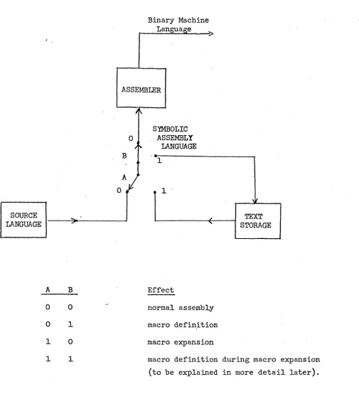
APPENDIX B: Table of Trimmed ASCII Code for-the SDS
930.
9-1
9-1
A-l
An assembler is a translator whose source language is assembly language
and whose object code is actual machine language. Assembly language is mostly
a one-far-one representation of machine language written in a symbolic form. Its value comes from being easier to read and from the facilities provided by
the assembler for doing calculations at assembly time. These range from simple
address calculations to complex conditional assemblies in which totally
different object programs may be generated, with the choice 8.JllOng them
depending on the values of a few parameters.
This section serves to define the terminology used. It is assumed that
*
the programmer is fnmiliar with the basic characteristics of the SDS 940 .
1.1 Basic Description of the Assembler
The assembler is a two-pass assembler with subprogram, literal,
macro, and conditional assembly capabilities.
1.2 Symbols
Numbers may be represented symbolically in assembly language by
symbols. A symbol is any string of letters and digits not forming a constant. (Constants are defined in Section 4.2). In particular, it
is not necessary that a symbol begin with a letter. Although symbols as written may be arbitrarily long, only the first six characters of a
symbol are used to distinguish it from others. When a symbol is used to
represent a memory address, it is called a label. Examples of symbols
are:
START ZlC A12 CALCULATE
1·3 Instructions, Directives, and Comments
Input to the assembler takes the form of a sequence of statements
called instructions, directives, or comments. Instructions are symbolic
representations of machine commands and are translated by the assembler
into machine language. Directives, by contrast, are messages which serve
to control the assembly process or create data. They mayor may not
generate output. Comments are ignored by the assembler, and serve only
to clarify the meanine of a program.
1.4
SubprogramsPrograms often become quite large or fall into logical divisions
which are almost independent. In either case it is convenient to break
them into pieces and assemble (and even debug) them separately. Separately
assembled parts of the same program are called subprograms.
Before a program assembled in pieces as subprograms can be run it is
necessary to.load the pieces into memory and link them. The symbols used
in a given subprogram are generally local to that subprogram. Subprograms
do, however, need to refer to symbols defined in other subprograms. The
linking process takes care of such cross references. Symbols used for it
are called external symbols.
1.5
LiteralsOften data is placed in programs at assembly time. It is frequently
convenient to refer to constants by value than by label. A literal is a
symbolic reference to a datum by value. The assembler allows any type of
expression to be used as a literal. Some examples of literals are:
=3*XYZ-2 . ='END' =EXTERN
1.6
RelocationA relocatable program is one in which memory locations have been
(for this ass~~Dler, DDT) can then place the assembled program into
core beginning at whatever location may be specified at load time.
Placement of the program involves a.small calculation. For example,
if a memory reference is to the nth word of a program, and if the program
is l08ded beginning at location k, the loader must transform the reference
into absQlute location n+k.
This calculatiQn should not be done to each word of a program since
sQme machine instructions (shifts, for example) do not refer to memory
locations. It is therefore necessary to inform the loader whether or not
to relocate the address for each word of the program. Relocation
infor-mation is determined automatically by the assembler and transmitted to
the loader as a binary quantity called the relocation value. If R = I
the operand is to be relocated; if R - 0 the operand is absolute.
Constants or data may similarly require relocation, the difference
here being that the relocation calculation should apply to all
24
bits of the940
word, not just·to the address field. The assembler accounts for thisdifference automatically.
It is possible to disable relocation in the assembler and to do
absolute assembly. In this event there is an option which produces a
paper tape which can be loaded using the
940
fill switch.1.7 Basic Assembly Procedure
During pass 1 of the two-pass process the operands of instructions and
some directives are scanned for the presence of single symbols. If a single
symbol is present, a table of symbols is searched. If absent, the symbol is
added to the table but marked as not yet defined, i.e., having no value.
Labels are placed into the· symbol table in similar fashion, except that
they are assigned the current value of the location counter, a word within
the assembler which contains the relative Rddress of the instruction. If
(this is taken to be an error).
At the end of pass 1 the symbol table is sorted. All symbols present'
h~ving no value are assumed to be external. These symbols are 'then output
by the assembler for later use by the loader. During pass 2 the labels
are not computed; rather, the operand fields of instructions and directives
are evaluated using the now known symbol values.
In absolute assemblies the scan for single symbols in pass 1 is disabled. This has the effect of doing away with external symbols~
1.8
Notation2.0 The Assembly Language
2.1 r.haracter Set
The classes of characters recognized by the assembler are as follows:
(a) digits
(1) octal 0-7
(2) decimal 0-9
(b) letters A-Z
(c) 'a1phanumerics 0-9 and A-Z
(d~ delimiters + -
* / ,
I ( ) =(e) special characters
<
>
?$ blank
(-] .
"
Note that the characters !
#
%
&
@ .' t which are normally found on standard Teletypes are not recognized by the assembler. Us~ of them in a programwill result in their being replaced by blanks.
2.2 Statements
Statements are logical units of input. They may be delimited either
by being placed on separate lines or by being separated with semi-colons.
Semi-colons do not serve as statement delimiters when used between single
quotes (as in the TEXT directive) or inside of matched parentheses (as in
arguments of macro calls). Examples of statements are
or
START LDA
START
MUL STA
LDA
DAT2l 2lB ANSWER
DAT2l; MUL 2lB; STA ANSWER
If a statement requires more than one line for any reason, it can .be
continued on the next line'by typing a + in the first column of the next line.
Thus:
START LDA DAT21; MUL 2IB; STA ANSWER THE OOM -+MENT ON THIS LINE REQUmES A CONTTIruJriITON
Each non-blank statement is an instruction, a directive, or a
c0mment. Blank statements are ignored. Comments begin with an asterisk;
they have absolutely no effect on the program being assembled and serve
only as annotations to clarify the meaning of the assembly langu~ge.
Directives and instructions are divided into four fields. The
fields are, from left to right, the label field, the operation field, the
operand field, and the comment field. The assembler is a free-form
assembler; its various fields are delimited by blanks rather than
restricting them to fixed places in a line. This is explained in more
detail below.
The label field is used mostly for symbol definitions. It begins
with the first character in the statement and ends on the first
non-alphanlrmeric character. (The blank is usually the only legal terminator.)
Thus,. in the following statements the symbol XYZ appears in label fields.
XYZ LDA =10
STA DEF;XYZ LDA =10; LDB* LMN
The operation field contains (usually) a symbolic operation code or
directive name. It begins with the first non-blank character after the
termination of the label field. In the statements above, each operation
field begins in a different position. Like the label field, the operation
field terminates on the first non-alphanumeric character. Legal
terminators are the blank, asterisk, semi-colon, and carriage return.
The operand and comment fieldS each begin with the first non-blank
character after the termination of the preceding field. The oper~nd
field terminates on the first blank or semi-colon not between matched
single quotes or parentheses. The carriage return always terminates the
or carri~ge return. This field, like the comment statement, is not used
by the assembler; it may contain anything.
2.3 Programs
A program consists of a sequence of statements terminated by an END
directive. Normally programs are assembled in relocatable form. A
program is assembled in absolute self-loading. form if it begins with an
ORG directive. It is possible (by using RELORG) to make an absolute
(a) Class 1 (normal instructions).
Class 1 instructions in general use the operand field. Its
absence implies the value zero. It is possible to specify for each
Class 1 instruction whether or not the operand field must be present. It is also possible to 'specify that bit 0 of the instruction word is to be set to one (as in SYSPOPs). There are two types of Class 1
instructions:
(1) type
°
14
The address is formed mod 2 . All instructions
making memory references are of this type.
(2) type 1
The operand is formed mod 29. This type is used for
shift instructions. If indirect addressing is used with
this type, the address is formed mod 214.
Class 1 instructions have the following form:
[[$]label] opcode[*] [operand[,tag]]- [comment]
Indirect addressing is signified by an asterisk tmroediately
following the operation code or by preceding the operand with ~ •
The use of the dollar Sign is explained in 3.2 The tag is used
to specify bits 0, 1 and 2 of the 940 instruction word.
(b) Class 2 (complete or full word instructions).
Class 2 instructions have no operand field. Indirect addressing
is signified by an asterisk immediately following the operation
code. Class 2 instructions have the following form:
(c) Numeric op codes.
Operation codes 'may be specified as decimal or octal numb~rs,
as for example:
[[$]label]
76B[*]
[operand[,tag]] [comment]The assembler shi~ts the numeric op code (modulo
177
8
)
left tothe correct position in the instruction word. In such cases, the
op code is assumed to be Class 1, type 0, no operand required,
and with bit 0 not set.
3·2
Use of the Label FieldA label identifies the instruction or data word being generated. The symbol used in the label field is given the current value of the location
counter. Instructions will have labels normally if they are referred to
elsewhere in the program, although it is not necessary that symbols defined
in this way be used in references. Symbols defined but not used are called
nulls; they are marked as such in the assembly listing and explicitly
typed out at the end of an assembly.
If the same symbol appears in the label field of more than one
-instruction, it is marked as a duplicate and given the newer value.
A $ preceding a label causes an external symbol definition (cf.
6.6).
3.3
Operand FieldThe operand field contains at most two arithmetic expressions (or a
literal and one expression) used to determine the operand and tag of the
machine command. The tag, if present, is evaluHted mod 23 and must be
absolute (i.e~ non-relocatable).
3.4
Alternate Conventions for Expressing Indexed&
Indirect AddressesIt is possible to express both the use of indexing and indirect
is placed at the beginning of the operand field. These characters are /
for indexing and ~ for indirect addressing. Thus, for example,
LDA VECTOR,2 is the same as LDA /VECTOR and
STA* POINTR is the same as STA H?OINTR
Similarly,
LDA* COMPLX,2 may be written either as
LDA / f-COMPLX or LDA ~COMPLX
Anything normally useful may follow the initial ~or /, for example
LDA 4 -=CHA IN (LDA* =CHAIN)
This alternate way of expressing indexing and indirect addressing
may be used by programmers as they choose. It was devised to simplify
the indication of these operations in the use of macros (see chapter 7).
3.5 Comment Field
The comment field is not processed by the assembler, but is copied
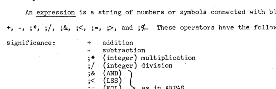
4.0 Expression Syntax
The assembler evaluates expressions as 24-bit, signed integers. Expressions
consist of constants and symbols connected by operators. Examples of expressions
are:
lOO-2*ABC(OR)DEF/27B
22 Cl2>DI9
Expressions are evaluated from left to right, some operators taking precedence
over others. As an expression is evaluated, a parallel cal.cu1atioz; of its
relocation value R. is made. Only absolute expressions (R
=
0) and ·re1ocatable expressions (R=
1) are 'legal (cf. 4.7).4.1 Operators
The operators recognized by the assembler and their precedence are
given below. Operators of highest precedence are applied first in
evaluation of expressions.
Operator Precedence
(a) unary
+ 4
4
(NOT) 4
(R) 4 (cf. 4.7)
(b) re lat iona1
(LSS) or < 3
(GRT) or> 3
(EQU) or
=
3(c) binary
*
2/
2(p,ND) 2
+ I
1
(OR) I
Note that some operators are more than one character long. These
are enclosed in parentheses to avoid confusion with symbols which would
~therwise look the same. Parentheses are therefore not allowed in
expressions to delineate terms and modify the order of evaluation.
The relational operators give rise to a value 1 if the relation is
true and
°
if false. There may be only one relCltional operator in anexpression.
4.2
ConstantsConstants are of three types: .
(a) decimal integers: one or more decimal cht.l.racters possibly
terminated with the letter D.
2129, 600D, -217
(b) octal integers: one or more octal characters possibly terminated
with the letter B and optionally a single-digit octal scaling
factor.
217, 32B, 4B3 (which is the same as 40008)
(c) string: '1-4 characters (except ,),
-All constants are absolute, i.e., their relocation value is O.
The assembler normally expects integers to be decimal. This can
be changed, however, by using a directive (OCT or DEC). In any case~
integers may be terminated with B or D, overriding the normal
inter-pretation of, integers. string constants are not normally useful in the
direct comp~tation of memory addresses, but exist basically to be used
in lite~als (cf. 5.0).
4.3 Classification of SymbolS
The assembler recognizes the following types of symbols:
(a) local symbols: These symbols are defined by their use in the
value is that of the location counter at their definition. They
are thus symbolic addresses of memory cells. These symbols are
relocatable (R
=
1) if the assembly is relocatable; if theassembly is absolute, they are absolute. Once having been
defined, a local symbol may not be redefined. Attempts to do so
are considered errors, and diagnostics result.
(b) equated symbols: Equated symbols may be defined by equating
them to an expression (using directives EQU, NARG, or NCHR).
Their relocation value will be that of the expression. Unlike
local symbols, equated symbols may be given new values' at any'
point in the program.
(c) current location counter symbol
(*):
The character*,
if usedin the proper context, is understood to mean the current value
of the location counter. It is relocatable or absolute
depending on the nature of the assembly ..
(d) external symbols: External symbols are those which are used·
but not defined in a given subprogram. They can be assigned no value, and it is not reasonable to regard them either as
absolute or relocatable. External symbols may be used only as
the sale object in an expression; other than its appearance as
a sole object, the external symbol may not be used in an
expression.
4.4
TermsTerms are either constants or symbols, optionally preceded by a unary
Qnd its relocation value. One unary operator -- special relocation, (R)
may set the relocation v3lue of a term to any value. This feature is
explained in much more detail in
4.7.
4.5·
ExpressionsExpressions may consist of one or more terms connected by binary operators,
or they may be .just a single external symbol. Their evaluation proceeds
from left to right using operators of decreasing precedence. For example,
let A = 100, B
=
200, and C = -1. ThenA+B*C/A
=
98
Again, letting A
=
543218'
B=
444448,
and C=
000778,
thenA(OR)B(AND)C
=
543658
4.6
Constraints of Relocatability of ExpressionsThe implementation of the assembler forces the following constraints
on the use of expressions:
(a) No relocatable term (R
=
1) may occur in conjunction with theoperators
*
orI.
In other words, no relocatable symbol may multiply, be multiplied by, divide, or be divided by anything.(b) In the absence of the special relocation operator (R) the
final relocation value of an expression may be only 0 or 1.
It is possible that the relocation value may attain other
values in the course of evaluation.
(c) I f the special relocation operator (R) appears in an expression, then the relocation value of the expression may be either 0 or
some other value K, where K is the special relocation radix. DDT
is informed by the assembler that special relocation is being used
in this case. DDT will then multiply the base address by K
4.7
Special RelocationThe special relocation feature has been provided to permit the
programmer limited use of expressions which are not absolute or singly
relocatable. To see why this is desirable, and how it works, consider
the process of assembling and loading a relocatable program. Let the
symbol A have value a. If one writes
LDA A
the assembler produces
076
aand marks the· instruction's address as being relocatable. Late~ when
~old to load the program beginning at base address b, DDT will form
076
a+bThus no matter where the pr~grrum is loaded, the memory reference will be to
the ath word from the base address.
Now suppose one writes
LDA 2*A·
The assembler, of course, can form
076
2*a.and presumab~ what DDT should form is
076
2*a+2*b=
076
2*(a+b)To do this, it must be told that b is to be multiplied specifically by 2.
Only one bit is reserved, however, for such information in the assembler's
binary output; it is this fact which causes the restriction that
expressions may have only the relocation values 0 and 1. And this
restriction can be gotten around (inelegantly) by the use of (R).
The following example give·s one of the main reasons for which (R) was.
Programs may make use of the string-handling 8YBPOPs of the
940.
-These instructions use string pointers, two-word objects containing
starting and ending character addresses. Now characters are packed
three per word. A character address therefore consists of the memory
address containing the ch~racter multiplied by 3 plus 0, 1, or 2
depending on the position of the character in the word. If a character
address is divided by 3, the quotient gives the word address and the
remainder the character position in the word.
To form a chara.cter address at assembly time, one must be able to
multiply a word ,address (a relocatable item) by a constant (in this
case, 3). This is the rea.son for special relocation. The statement
DATA (R)A+l
will produce the value
3*a+l
together with a notation to DDT that special relocation applies to that
value.
DDT will then form the value
(3*a+l)+3*b = 3*(a+b)+1
symbol, representing a relocatable word address, may thus be used to form
character addresses in string pointers. There are other e~amples for the
need for special relocation, but they will not be mentioned here. Let it
suffice to say that special relocation is merely a device to make up
partially for the rather severe relocation constraints the assembler
imposes upon programmers.
It should be pointed out that the multiplicative constant associated
with (R) in the example above was 3 because of the nature of string
pointers. This constant is called the special relocation rndix. It need
RAD. Because of the relative importance of string pointers, however,
the assembler is initialized with this value set to
3;
it is henceunnecessary to use RAD to set it to 3 unless it has been changed for
5.0
LiteralsProgrammers frequently write such things as
LDA FIVE
where FIVE is the name of a cell cont~ining the constant
5.
The programmermust remember to include the datum FIVE in his program somewhere. This can
be avoided by the use of a literal.
LDA =5
will produce automatically a location containing the correct constant in the
program. Such a construct is called a literal.
Literals are of the form
=expression
When encountering a literal, the assembler first evaluates the expression and looks up its vnlue in a table of literals constructed for each subprogram.
If it is not found in the table, the value is placed there. In any case the
literal itself if replaced by the location of its value in the literal table.
At the end of assembly the literal table is placed after the sub-program~
The following are examples of literals:
=10
=2=AB
=ABC*20-DEF/l2
='HELP'-(This is a conditional literal. Its value will be 1 or 0 depending on whether 2=AB at assembly time.) .
Some programmers tend to forget that the literal table follows the
subprogram. This could be harmful if the program ended with the declaration
of a large array using the statement
ARRAY BSS 1
It is not strictly correct to do this, but some programmers attempt it anyway
on the theory that all they wan.t to do is to name the first cell of the array.
The above statement will do that, of course, but only one cell will be reserved
plnced in the following cells which now fall into the array. This is, of
course, an error. Other th~n the above exception, the programmer need not
6.0
DirectivesThere is a large number of directives associated with this assembler.
Although many of the directives are similar, ea·ch in general .has its own
syntax. A concise summary is given below:
Class
Data Generation:
Value Declaration:
Assembler Control:
Output
&
Listing Control:Macro Generation
&
ConditionalAssembly: Directive COpy DATA TEXT ASe EQU EXT NARG NCHR OPD FOPD
BES
BSS ORG END DECOCT
RAn FRGT IDE NT DELSYM RELORG RETHEL FREEZE NOEXT LIST NOLIST PAGE REM MACRO ENDM RPr eRPl' ENDR IF ELSF ELSE· ENDF Use/FunctionFacilitates use of RCH command Generation of data
Generation of text Generation of text
Setting or changing symbol values Defining external symbols
See See.
\
Defining new op codes Defin.ing po~ codes
Block ending symbol Block starting symbol Origin: absolute assembly End of program
Interpret integers as decimal Interpret integers as octal Set special relocation radix Forget name of symbol
Identify name of program
Do not transmit symbols to loader See ·6.21
See 6.22
Preserve sYmbols and macros Do not create external symbols
Set listing flags Reset listing flags
Skip to new page on listing Type out remarks in pass 2
Head of· macro body End of macro body Begin repeat body
Begin conditional repeat body End repeat body
Begin if body
6.1 COpy Generalized Register Change Command
[[$]label] COPY sl,s2,s3' ... [comment]
where s. are symbols from a special set ass5ciated with the COpy directive
The COPY directive produces an RCH instruction. It takes in its operand
field a series of special symbols, each standin~ for a bit in the address
field of the instruction. The bits selected by a given choice of symbols
are merged together to form the address. For example, instead of using
the instruction CAB (04600004), one could write COpy AB. The special
symbol AB has the value 00000004.
The advantage of the directive is that unusual combinations of bits
in the address field -- those for which there exist normally no operation
codes -- may be created quite naturally. The special s~~bols are mnemonics
for the functions of the various bits. Moreover, these symbols have this
special meaning only when used with this directive; there is no restriction
on their use either as symbols or op codes elsewhere in a program. The
symbols are:
Symbol Bit Function
A 23 Clear A
B 22 Clear B
AB 21 Copy (A) -+B
BA 20 Copy (B) -+A
BX 19 Copy (B) -+X
XB 18 Copy (X) -+ B
E
17
Bits 15-23 (exponent part) onlyXA 16 Copy (X) -+ A
AX. 15 Copy (A) -+ X
N 14 Copy - (A) -+ A (negate A)
X 2 Clear X
To exchange the contents of the B and X registers, negate A, and only
for bits 15-23 of all registers, one would write
Of course, the symbols may be written in any order.
Clever programmers please note: This directive facilitates nicely
some special RCH functions which might not otherwise be .attempted (it
is usually too much trouble). For example,
COPY AX.,BX
has the effect of loading into
X
the logical ·OR (merging) of the A andB
registers. Interested readers are referred to the SDS 940 manual for more
details of the RCH instruction.
6.2 DATA Generate Data
[ [$]label-] DATA [comment]
The DATA directive is used to produce data in. programs. Each expression
in the operand field is evaluated and the 24-bit values assigned to
increasing memory locations. One or more expressions may be present.
The label is assigned to the location of the first expression. The effect
of this directive is to create a list of data, the first word of which may
be labeled.
-Since the expressions are not restricted in any way, any type of
data can be created with this directive. For example:
DATA lOO,-217B,START,AB*2/DEF, 'NUTS',5
6.3 TEXT Generate Text
[[$]label] TEXT 'text' [comment1·
or,
[[$]label] TEXT expression,text [comment]
The TEXT directive is used to create a string of 6-bit trimmed ASCII
cnaracters, packed four to a word and assigned to increasing memory
locations. The fi~st word of the string may be labeled. The string to be
case above)' or by preceding it with a word count (as in the second case).
The second form of the directive must be used, of course, if the string
contains one or more quotes. A pote~tial hazard arising here should be pointed out. If a stntement contains a single quote (or any odd number
of them), it will not terminate with a semi-colon; a carriage return must
be used.
TEXT 4,THIS WON'T "WORK; TEXT 4,DISASTER AHEAD
In the line above the semi-colon will be part of the text, and the second
statement will be interpreted as being in the "comment field,
TEXT
TEXT
4, THIS WILL '
I,A-OK
In the first form of the directive, characters in the last word are
left-justified and remaining positions filled in by blanks (octal 00).
In the second form, sufficient characters are pucked to satisfy the word
count.
6.4 ASC Generate Text with Three Characters per Word
This directive is identical in form and use to TEXT, except that
8-bit characters are packed three per word". The 940 string processing
system normally deals with such text.
6.5 EQ,U Equals
[$]symbol EQU expression [comment]
The EQU directive causes the symbol in its label field to be defined
and/or given the value of the expression. The expression must have a
value when EQU is first encountered; i.e., symbols present in it must have
been previously"defined. It is permissible to redefine by EQ,U any symbol
previously defined by EQ,U (or NARG or NCHR, cf.below). This ability is
6.6
EXT Define External SymbolThere are four ways whic? may be used to define external symbols.
(a) $label opcode or directive operand, etc.
The $ preceding the label causes the symbol in the label field
to be defined externally at the same time it is defined locally.
(b) symbol EXT (comment not permitte~)
The symbol given in the label field is defined externally.
This symbol must have been defined previously in the program.
The operand and comment fields must be absent.
Both of the above forms have the same effect; the name and value of a local
symbol is given to the loader for external purposes.
Occasionally it is desirable to define 'an external symbol whose name
is different from that of a local symbol; or an external symbol may be
defined in terms of an expression involving local symbols. There are two ways of doing this.
(c) $symbolEQU expression
(d) symbol EXT exp.ression
[comment]
[comment]
In (c) above the symbol is defined both locally ~nd externally at the same
time. (d) differs subtly in that the symbol in the label field is defined only externally; its name and value are completely unknown to the local
program.
The feature (d) above is particularly useful in situations where two or
more subprograms loaded together have name.conflicts. For example, suppose
programs A and B both make use of the symbol START, and A not only refers
to its own START but Bls as well. The latter references can be changed to
BEGIN. Then into program B can be inserted the line
BEGm EXT START
Occasionally, after having written a program, one would like to make
a list of local symbols to be externally defined. A built-in macro ENTRY
serves this function. That it is a built-in macro is irrelevant; the
programmer may think of it as a related directive. Thus
ENTRY A,B,C,D, ...
is precisely equivalent to
A
EXTB EXT
C EXT
D· EXT
6.7
NARG Equate Symbol to Number of Arguments in Macro Call[$]symbol NARG [comment]
This directive may be used only in macro definitions. It is mentioned
here only for completeness. It operates exactly as EQU except that in place of an expression in the operand field, the value of the symbol is set to the number of arguments used in calling the macro currently being
e~anded. Cf.
7.9
below.6.8
NCHR· Equate Symbol to the Number of Characters in Operand[$]symbol NCHR operand [comment]
This directive is intended for use mostly in macro definitions, but it may be used elsewhere. It operates exactly as EQU except that in place
of an expression in the operand field, the value of the symbol is set to
the number of characters included in the operand field. A further
6.9
OPD Operat'ion Code DefinitionThe OPD directive gives the programmer the facility to add to the
existing table of operation codes kept in the assembler new codes or to
change the equivalences of current ones. The form of OPD is:
opcode OPD expression,class[,ar[,type[,sb]]] [comment]
where: 1) class must be 1 or 2 (cf. Section
3.1).
2) ar (address r'equired) may be 0 or 1
3)
type may be 0 or 1 (cf. Section3.1).
4) sb (sign bit) may be 0 or 1
Quantities governed by the optional terms above
(2,3
and 4) are set tozero if the terms are missing. As examples of how the directive is used,
some standard machine instructions are de'fined as follows:
CLA
LDA
RCY
OPD
OPD
OPD
0460000lB,2
76B5,1,1
662B4, 1, 1, 1 (TYPE 1
=
SHIFT)A hypothetical SY8POP LLA might be defined by
LLA OPD 110B5, 1, 1,0,1
(class 1, address required, type 0, Sign bit set}.
In operation, the assembler s imply adds new op codes def,ined by OPD
to its opcode table. This table is always searched backward, so the new
codes are seen first. At the beginning of the second pass the original
table boundary is reset; thus if an opcode is redefined somewhere during
assembly, it is treated identically in both passes.
6.10 POPD Programmed Operator Definition
In programs containing POPs it is desirable to provide the POPO directive. This directive works exactly like OPO and is used in the same
in the pop transfer vector (1008 - 177
8) a branch instruction to the body of the pop routtne.
In order to do this the assembler must know two things:
(l) the location for "the branch instruction in the transfer vector and
(2) the location of the pop routine (i.e. the address of the branch
instruct ion) .
Item (l) is given by the pop code itself. Item (2) is provided by the
convention that the POPD must ~ediately precede the body of the pop
routine. The address of the branch instruction placed in the transfer
vector is the current value of the location counter.
I f the automatic insertion of a word in the pop transfer vector is not desired, then OPD should be used instead. An example of this case
would occur in a subprogram containing a pop whose routine is found in another subprogram.
6.11 BES Block Ending Symbol
[[$]label] BES express~on [comment]
The use of BES reserves a block of storage for which the first location
after the block may be labeled (i.e. if the label is given). The block
size is determined "by the value of the expression; it must therefore be
absolute, and it must have a value when BES is first encountered, (symbols
present must have been previously defined). BES is most useful for
labeling a block which is to be referred to by indexing using the BRS
instruction (where the contents of X are usually negative). For example,
to add together the contents of an array one might write:
LDX =-100 ARRAY HAS 100 ENTRIES
CIA
LOOP ADD ARRAY,2 NEGATIVE mnEXmG HERE
BRX *-1 STA RESULT HLT
6.12
BSS Block .Starting Symbol[[$]label] BSS expression [comment]
The use of BSS reserves a block of storage for which the first word may
be labeled (if the label is given). The block size is determined by the
value of the expression; it must therefore be absolute, and it must have
a value when BSS is first encountered. ·The difference between BSS and BES
is that in the case of BSS the first word of the block is' labeled, whereas
for BES the first word after the block is labeled by the associated symbol.
BSS is most useful for labeling a block which is referred to by positive
indexing (cf.
6.11
above).6.13
ORG Program OriginORG expression [comments]
The use of ORG forces an absolute assembly. The location counter is
initialized to the value of the expression. The expression must therefore
be absolute, and it must have a value when ORG is first encountered.
Pn ORG must precede·the first instruction or data item in an absolute
program, although it does not necessarily. have to be the first statement~
The output of the assembler will have a bootstrap loader at the front
which is capable of loading the program after initiation by the
940
FILL switch.
6.14
END End of AssemblyEND [expression]
The END directive terminates the assembly. For'relocatable assemblies,
no expression is used. For absolute assemblies the expression gives the
starting location for the program. When assembling in absolute mode,
the 'assembler produces a paper tape which can be read into the machirte
with the FILL switch, i. e., out of the time-sharing mode. If the
on this paper tape .rill h~.lt after the tape has read in. Otherwise, control will automatically transfer to the location designated in the expression •
. 6.15
DEC Interpret Integers as DecimalDEC [comments]
Integers terminated with B or D are always interpreted respectively as
being oct2l or decim~l. On the other hHnd, integers not terminHted with
these letters may be interpreted either as decimal or octal depending on
the setting of a switch inside the assembler. The mode controlled by this
switch is set to decimal by the above directive.
When the assembler is started this mode is initialized to decimal .
. Thus, the DEC directive is not really necessary unless the mode has been
changed to octal and it is desired to return it to decimal.
6.16
OCT Interpret Integers as OctalOCT [comments]
As noted in
6.15
above, this directive sets a mode within the assemblerto interpret unterminated integers as octal. When the assembler is
started this mode is initialized to decimal. Thus, the OCT directive
must be used before unterminated octal integers can be written.
6.17
RAD Set Special Relocation RadixRAD expression [comment]
As explained in
4.7
it is possible in a limited way to havemultiple-relocated symbols. This action is performed when the special relocation
operntor (R) is used. The value of a symbol preceded by (R) is multiplied
by a constant called the radix of the special relocation. The loader is
informed of this situation so that it can· multiply the base address by this
relocation was developed specifically to facilitate the assembly of string
pointers (cf.
4.7),
this constant is initialized to3.
It it is desiredto change its value, however, the RAD directive must be used. The value
of the expression in the opera~d field sets the new value of the radix. It must be absolute, and the expression must have a value when it is
first encountered.
6.18
FRGT Forget Name of SymbolFRGT [comment]
where s. are previously defined symb'ols
l.
The use of FRGT prevents the symbol(s) named in its operand field from
being listed or delivered to DDT. FRGT is especially useful in situations,
for example, where symbols have been used in macro expansions or conditional.
assemblies. Frequently such symbols have meaning only at assembly time;
they have no connection whatever with the program being assembled. When
DDT is later used, however, memory locations sometimes are printed out
in terms of these meaningless symbols. It is desirable to be able to .
keep these symbols from being delivered to DDT.
6.19
IDENT Program Identificationsymbol IDE NT [comment]
IDENT causes the symbol found in its label field to be delivered to DDT
as a special identification record. DDT uses the IDENT name in conjunction
with its treatment of local symbols: in the event of a name conflict
between local symbols in two different subprograms, DDT resolves the
ambiguity by allowing the user to concatenate the preceding IDENT name
to" the symbol in question ..
IDENT statements are otherwise useful for editing purposes. They
DELSYM [comment]
DELSYM inhibits the symbol table and opcodes defined in the course of
Hssembly from being output for later use by DDT. Its main purpose is to
shorten the object code output from the assembler. This might be
especially desirable for an absolute assembly which produces a paper tape
which is to be filled into the machine.
6.21 RELORG Assemble Relative with Absolute Origin
RELORG expression [comment]
On occasion it is desirable to assemble in the midst of otherwise normal program a batch of code which, although loaded into core in some position,
is destined to run from another position in memory. (It will first
have to be moved there in a block.) This is particularly usefUl when
preparing program over~ays.
RELORG, like ORG, takes an absolute expression denoting some origin
in memory. It has the following effects:
(d.) The current value of .the location counter is saved, i.e. the
value of the expression and in its place is put the absolute
origin. This fact is not revealed to DDT, however; during
loading the next instruction assembled will be placed in the
next memory cell available as if nothing had happened.
(b) The mode of assembly is switched to absolute without changing
the object code format; it still looks like relocatable binary
program to DDT. All symbols defined in terms of the locHtion
counter will be absolute. Rules for computing the relocation
value of expressions are those for absolute assemblies.
Some examples of the use of RELORG follow:
(l)· A program begins with RELORG 300B and ends with END. The
assembler's output represents an absolute program whose origin is 003008
but which can be loaded anywhere using DDT in the usual fashion. (It
is, of course, necessary to move the program to location 003008 before
executing it.)
(2) A progrrun starts and continues normally as a relocatable program.
Then there is a series of RELORGs and some RETRELs. The effect is as
shown below:
}
Normal relocatable program .RELORG . 100
J
Absolute program origined to 100RELORG ·200
}
Absolute program origined to 200RETREL
J
Normal relocatable programRELORG 300
J
Absolute progrrun origined to 300END
6.22 RETREL Return to Relocatable Assembly
RETREL [comment]
This directive is used when it is desired to return to relocatable assembly
after having done a RELORG. It is not necessary to use RETREL unless· one
The effects of RETREL are
(a) to restore the L0cation counter to what it would have been
had the RELORG(S) never been used, and
(b) to return the asz emb1y to re1ocatab1e mode.
6.23 FREEZE Preserve Symbols, Op-codes, and Macros
FREEZE [comment]
It is' sometimes true when ~ssembling various sub-programs that they share
definitions of symbols, op-codes, and macros. It is possible to cause the
assembler to take note of the current contents of its symbol and opcode
tables and the currently defined macros and include them in future
assemblies, eliminating the need for including copies of-this information
in every subprogram's source language. This greatly facilitates the
editing of this information.
When the FREEZE directive is used, the current table boundaries for
symbols and opcodes and the storage area for macros is noted and s8ved away
for later use. These tables may then continue to expand during the current
assembly. (A separate sub-program may be used to make these definitions.
It will then end with FREEZE; END.) The next assembly may then be started
with the table boundaries returned to what they were when FREEZE was last
executed. This is done by entering the assembler at its continue entry
point, i.e. one types
(fJ
CONTlliUE ARPAS.Note that when the assembler has been pre-loaded with symbols, opcodes
and macros, it cannot be released (i.e. one cannot use another. SUb-system
6.24
NOEXT Do Not Create External SymbolsBecause of its subprogram capability, the assembler assumes
auto-matically that symbols which are not defined in a given program are external
and will be defined in another subprogram. It does not therefore list out
the use of. such symbols as errors.
If a program is in fact a free-standing program, i.e. if it is
supposed to be complete, then clearly symbols which are not defined are
errors and shouIa be so noted in assembly. The NOEXT directive simply
pr'events external symbols from being established; thus undefined symbols
are noted as errors. The directive must b~ used at the beginning of a .
program before instructions or data have been assembled. Its use affects
the entire program. Its form is
NOEXT [connnent)
6.25 LIST Turn Specified Listing Controls
on
6.26
NOLIST Turn Specified Listing Controls OffMost assemblers provide a means of listing a program during assembly,
i.e. printing out such items as the location counter, binary code being
assembled, source program statement, etc. The association of these items
,
on one page is frequently of great help to programmers. Twodirectivesj
LIST and NOLIST, control this process. Their form is as follows:
LIST}
NOLIST [comment]
where the s. are from a set of special symbols having
l.
meaning only when used with these directives.
There' are many listing options for this assembler. A list of special
mnemonic symbols used in conjunction with these two directives is given
NOLIST. They may be used at any other time for any particular purpose.
The special symbols are:
Symbol·
1
2
LCT BlN
SRe
COM
Me
ME
EXT
NUL
Meaning
Listing during pass 1. Listing format will be controlled by other parameters.
Listing during pass 2. Listing format will be controlled by other parameters.
Listing of location counter value (see below)
Listing of binary object code or values (see below)
Listing of source language (see below)
Listing of comments (see below)
Listing of macro calls· (see below)
Listing of certain directives during macro
expansions (EQU, NCHR, NARG, RPI', CRPl', ENDR, IF,
ELSF, ELSE, ENDF, ENDM).
Listing of external symbols at end of assembly
Listing of null
&
duplicate symbols at end ofassembly.
P.s ()n example of the meanings of various symbols above, consider the line
of code A21 STB OUTCHR SAVE POINTER. It might list as
~236~2l~ ~2l S~ OUTC~ ~
LCT BIN SRC COM
It is not necessary to include each symbol"possib1e, but rather only those
parameters for which changes a.re desired. It is, in fact, not necessary
to give any symbols.
When the assembler is started, it initializes itself in the followinB
LIST LCT,BIN,sRC,COM,MC,EXT,NUL
NOLIST 1,2,ME,SYT
The actual format of the assembly listing is controlled by the current
combination of par8meter values. The parameters are independent items
except for the parameters MC and ME. In this case it is more reasonable" to think of their combination. Thus:
ME
o
o
1
o
o
11 1
Effect
List outer level macro calls only
List all macro calls and code generated, but
suppress listing of certain directives (see ME
in table above).
List no macro calls, but rather all code generated
except for certain directives.
List everything involved in macro expansions.
Regardless of the list control parameters which have been given to
the assembler, it can be made to begin listing at- any time in either pass
simply by typing a single rubout (typing a second rubout in succession will
abort the assembly). Listing having been started in this manner can be
stopped by typing the letter S.
6.27
PAGE Begin New Page on Assembly ListingPAGE [comment]
This directive causes a page eject on the assembly listing medium
unless a page eject has just been given. It is used to improve the
appearance of the assembly listing.
6.28
REM Type Out Remarks in Pass 2REM remark to "be typed
its operand and comments fields to be typed out either on the Teletype
or whatever file has been designated as the output message device. This
typeout occurs regardless of what listing modes are set. The directive
may be used for a variety of purposes. It may inform the user of the
progress of assembly. It may give him instructions on what to do next
(this might be especially nice for complicated assemblies). It might
announce the last date the source language was.updated. Or, it might be
used within complex macros to show which argument substrings have been
created during expansion of a highly nested macro (this for debugging
7.0 Macros and Conditional Assembly
Assemblers with good macro and conditional assembly capability can have
surprising power. This assembler features such capability.
In
this sectionthe facilities for dealing with macros and conditional assembly will be
discussed. Many examples will be given.
7.1
Introduction to MacrosOn the simplest level a" macro name may be thought of as an abbreviation or shorthand notation for one or more assembly language statements.
In
this respect it is like an opcode. The opcode is the name of a binary
machine command, and "the macro name is the name of a sequence of assembly
language statements.
EXAMPLE 7-1.
The
940
has an instruction for skipping if the contents of a specifiedlocation are negative, but none for testing the accumulator. SKA (skip
if memory and accumulator do not compare ones) will serve when used with
a cell whose contents mask all but the sign bit. The meaning of SICA used
in this way is "skip if' A positive. n Thus a programmer will write
SKA BRU
=4B7
NEGCAS NEGATIVE CASE
Programs, however, are more than likely to have a logical need for
skipping if the accumulator is negative. In these situations the programmer must write
SKA BRU BRU
=4B7 *+2
roSCAS POSITIVE CASE
Both of these situations are awkward in terms of assembly-language
But we have, in effect, just developed simple conventions for doing
the operations SKAP and SKAN (skip if accumulator positive or negative).
Let these operations be defined as macros.
S~P MACRO
S~ =4B7
E~M
SAAN MACRO
8M =4B7
~U *+2
E~M
Now more in keeping with the operations the programmer has in mind
--he may write
A22 SMN
~U P08CAS
The advantages of being able to use S~P or 8KAN should be apparent.
The amount of code written in the course of a program is reduced. This
in itself tends to reduce errors. A greater advantage is that SKAP and
SKAN are more indicative of the action that the programmer has in mind.
Programs written in this way tend to be easier to read. Note, incidentally,
as shown above that a label may be used in conjunction with a macro. Labels
used in this way are usually treated like labels on instructions; they are ..
assigned the current value of the location counter. This will be discussed
in more detail later. 7.2 Macro Definition
Before discussing more complicated use of macros, some additional
vocabulary should be established. A macro is an arbitrary sequence of
assembly-language statements together with a symbolic~. During
assembly it is held in an area of memory called text storage. Macros
may be created or defined. To do this one must give (1) a name and
beginning of the sequence of statements in a macro are designated by
the use of the MACRO directive (see ex. 7-1 above).
name MACRO
ENDM
The end of the sequence of statements in a macro is signalled by the ENDM directive.
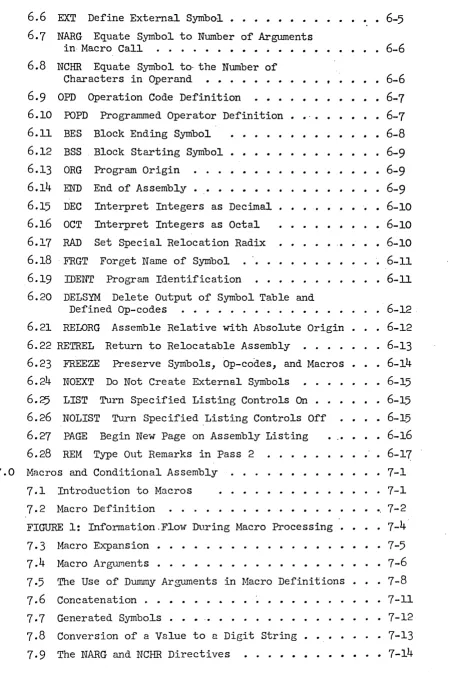
The reader should now refer to Figure 1. When the assembler
en-counters a macro definition (i.e., when it sees a MACRO directive), switch
B is thrown to position 1. The programmer's source language is merely
copied into text storage; note in particular that the assembler does not
do any processing during the definition of a macro. Switch B is put back
to position 0 when ENDM is encountered.
It is possi~le that within a macro definition other definitions may
be imbedded. The macro defining machinery counts the occurrences of the
MACRO directive and matches them against the occurrences of ENDM. Switch
B is placed back in position 0 actually only when the ENDM matching the
last MACRO is seen. Thus MACRO and ENDM constitute opening and closing
brackets around a segment of source language. Structures like the
SOURCE LANGUAGE
A 0 0 1 1
o
B 0 1 0 1
Binary Machine Lan a e
r---~~'----~
ASSEMBLER
SYMBOLIC ASSEMBLY
LANGUAGE
1
1°
Effect
normal assembly
macro definition
macro expansion
macro definition
(to be explained
TEXT
STORAGE
during macro expansion
in more detail later).
namel MACRO
name2 MACRO
name 3 MACRO
]
ENDM name4 MACRO
]
ENDMENDM
name5 MACRO
]
ENDM
ENDM
The utility of this structure will not be discussed here. Use of this
feature of imbedded definitions should in fact be kept to a minimum since
the implementation of this assembler is such that it uses large amounts
of text storage in this case. What is important, however, is an
under-standing of when the various macros are defined. In particular, when
namel is being defined, name2,3, etc. will not be defined; they are
merely copied unchanged into text storage. Name2 will not be defined
*
until namel is used .
7.3 Macro Expansion
The use of a macro name in the opcode field of a statement is referred to as a call. The assembler, upon recognizing a macro call, moves switch A
to position 1 (again see Figure 1). Input to the assembler from the
original source language ceases temporarily and comes instead from text
storage. During this period the macro is said to be undergoing expanSion.
It is clear that a macrO must first be defined before it is called. An expanding macro may include other macro calls; and these, in
turn·, may call still others. In fact,· macros may even call themselves
(when this makes sense). This is called recursion. Examples of the
recursive use o~ macros are given later. When within a macro expansion
a new macro expansion begins, information about the progress of the current
expansion is put away. Successive macro calls cause similar information
to be saved. At the end of each expansion the information about each
previous expansion is restored in inverse fashion. When the final
expansion terminates, switch A is placed back in position
o.
Input then resumes from the source language program.7.4
Macro ArgumentsNow let us carry example
7-1
one step further. One might argue thatthe action of skipping is. itself awkward. It might be preferable to write
macros BRAP and ~ (branch to specified location i~ contents of accumulator
are positive or negative). How is one to do this? The location to which
the branch should go is not known when the macro is de~ined; in fact,
different locations will be used from call to call. The macro processor,
therefore, must enable the programmer to provide some of the information
for the macro expansion at call time •. This is done by permitting dummy
arguments in macro definitions to be replaced by arguments (i.e., arbitrary
substrings) supplied at call time. Each dummy argument is referred to in
the macro definition by a subscripted symbol. This symbol or dummy ~