Volume 2009, Article ID 520287,12pages doi:10.1155/2009/520287
Research Article
Exploiting Transmit Buffer Information at
the Receiver in Block-Fading Channels
Dinesh Rajan
Department of Electrical Engineering, Southern Methodist University, Dallas, TX 77205, USA
Correspondence should be addressed to Dinesh Rajan,[email protected] Received 1 February 2008; Revised 30 April 2008; Accepted 29 July 2008 Recommended by Petar Popovski
It is well known that channel state information at the transmitter (CSIT) leads to higher throughput in fading channels. We motivate the use of transmit buffer information at receiver (TBIR). The thesis of this paper is that having partial or complete instantaneous TBIR leads to a lower packet loss rate in block-fading channels assuming the availability of partial CSIT. We provide a framework for the joint design and analysis of feedback (FB) and feed-forward (FF) information in fading channels. We then introduce two forms of TBIR—statistical and instantaneous—and show the gains of each form of TBIR using a heuristic scheme. For a Rayleigh fading channel, we show that in certain cases the packet error rate reduces by nearly an order of magnitude with just one bit of feed-forward information of TBIR.
Copyright © 2009 Dinesh Rajan. This is an open access article distributed under the Creative Commons Attribution License, which permits unrestricted use, distribution, and reproduction in any medium, provided the original work is properly cited.
1. Introduction
It is well known that the Shannon capacity of a discrete mem-oryless channel (DMC) does not increase with feedback from the receiver [1]. However, the capacity of fading channels increases with channel knowledge at the transmitter, and the capacity gain has been quantified for both single-antenna [2] and multiple-antenna [3] systems. Capacity with channel state information (CSI) at both transmitter and receiver has been studied [4], and the effect of errors on the channel knowledge has been quantified [5, 6]. Also, see [7] for a comprehensive review of communication through fading channels. The importance of incorporating traffic conditions in physical layer design has been well recognized [8–10], and cross-layer optimization has been an area of active recent research [11–16]. The use of queue information to optimize physical layer design has been investigated in many settings [17–20].
In this paper, we consider delay-bounded transmission of variable bitrate (VBR) traffic through a block-fading chan-nel. We propose to use transmit buffer information at the receiver (TBIR), and discuss an exemplary implementation system. The novelty in the proposed system is twofold. (i) A new transmission system architecture with a feed-forward channel that transmits queue state information from the
transmitter to the receiver is introduced, and (ii) the CSI that is sent to the transmitter via a feedback channel is chosen adaptively based on instantaneous or statistical knowledge of TBIR (the terms buffer and queue are used interchangeably in this paper). The design objective is to minimize overall packet loss for a given buffer size under a long-term power constraint.
The main contributions of this paper may be succinctly summarized as follows.
(i) We provide a framework for the joint design and analysis of feedback (FB) and feed-forward (FF) information over a block-fading channel. We con-sider two specific forms of TBIR, namely, statistical and instantaneous. The statistical or instantaneous FF information is used to adapt the mechanism that generates the FB information. In particular, a scalar quantizer of the channel fading gain is considered to generate the FB information, and this quantizer is computed based on the available TBIR.
some simple cases. It turns out that having just one additional bit of FF information can provide about 1 dB saving in power.
(iii) The performance gain of using FF information is also quantified using a simple practical adaptive QAM-based multirate transmission scheme.
The use of FF information does not provide any gain in the two extreme cases of full CSIT and no CSIT. When complete CSIT is available, the number of packets to transmit and the transmission power are determined jointly on the channel and buffer conditions. Also, when no CSIT is available, the transmission rate and power cannot be adapted based on channel conditions, and the use of FF information does not provide any performance benefits. However, for finite (nonzero) FB rates, FF information can lead to reduction in average packet loss. At the receiver, the channel state information (typically, fading amplitude) is measured and quantized to a finite number of bits. If transmit buffer information is not available at the receiver, the quantization thresholds are fixed. However, when buffer information is available at the receiver, the quantization thresholds are adapted based on the TBIR available.
The TBIR is applicable in any point-to-point communi-cation system. In this paper, we consider only a frequency division duplex (FDD) system (in time division duplex (TDD) systems, the channel information can be obtained from data received in prior time slots without requiring explicit FB from the receiver to the transmitter, and such systems are not considered here). The proposed design can be implemented very easily in an 802.11-based WLAN system, where a handshaking mechanism (exchanging RTS and CTS packets) is used prior to actual data transmission. There are also schemes which transmit quantized buffer occupancy information to the receiver in multiuser scenarios; the goal in such situations is to provide fairness or throughput guarantees. In this paper, buffer information is sent to the receiver, even in single-user scenarios, to reduce packet error rate by making more efficient use of the channel state information at the receiver. In a multiuser scenario, information on the various users’ transmit buffers can be used both for outage reduction (at the physical layer) and to implement fairness (at MAC layer). For uplink transmissions in cellular systems, even though FF information has to be transmitted from the mobile handset, which could have limited resources, the proposed method can be used to additionally ensure fairness among flows. For downlink transmission, since feedback from receiver to transmitter is limited, feed-forward information can be used to reduce packet loss.
For simplicity of analysis, amemorylesssource with an i.i.d. packet arrival distribution is considered. The analysis directly extends to Markovian source arrivals. Although more sophisticated source models exist, it turns out that the analysis is nontrivial even with these simplified models. Hence, we restrict ourselves to such simple sources in this paper. To demonstrate the applicability of the results, a block-fading channel with Rayleigh fading statistics is used. However, the proposed methods are applicable in general for
any block-fading channel, with other fading statistics. We consider a system with finite buffer length, which also results in an upper bound on the average packet delays. Further, with finite buffer length, there is a finite probability of buffer overflow. The overall design objective is to minimize the total packet loss rate resulting from buffer overflows and errors in the transmission over the channel.
The remainder of this paper is organized as follows. In
Section 2, we present the basic system under consideration. Sections3,4, and 5focus, respectively, on packet loss rate analysis and optimization with no TBIR, statistical TBIR, and instantaneous TBIR. Numerical results are presented in
Section 6. Finally, we conclude inSection 7.
2. System Model and Problem
Formulation
Consider a time-slotted system in whichanfixed-size packets arrive at the transmitter during time slotnand are stored in a buffer ofL-size packets before transmission. Letqnandun denote, respectively, the number of packets in the buffer and the number of packets transmitted during time slotn. The buffer update is given byqn+1 = min(qn+an−un,L). For simplicity of exposition, we consider a memoryless source arrival model with the distribution of packet arrivals given by Pr(an=l)=cl, l=0,. . .,M, whereMis the maximum number of packet arrivals in one time slot. Clearly, for a valid distribution, cl ≥ 0 and
M
l=0cl = 1. The analysis and results in this paper can be easily extended to other traffic models. Using Little’s law [21], the finite buffer length imposes an upper bound on the average delay experienced by the traffic. Further, if a first-come first-serve (FCFS) ordering of the packets in the buffer is assumed, along with a work-conserving scheduler, then the finite-length buffer also implies an upper bound on the absolute delay experienced by the packets.
We consider transmission over a block-fading channel, and assume that the length of one time slot equalsTc, the number of symbols in the coherence interval of the channel. The transmit signal xn depends on the number of packets transmitted in each time slot and the coding and modulation schemes. The complex received signalyn is given by yn =
hnxn+zn, whereznis the additive noise which is modeled as being circularly symmetric Gaussian with zero mean and covariance σ2I
Tc, and hn is the channel gain in time slot
n. The real and imaginary parts of hn are assumed to be independent zero-mean Gaussian, each with variance 1/2. The transmit signalxn, the received signalyn, and the noise at the receiverznareTc-dimensional complex vectors, where
Tcis assumed to be a positive integer.
The average packet loss (Π) depends on the packet loss due to buffer overflowsΠb and the frame error rate of the actual coding scheme. In this paper, we use the probability of outage (2) to bound the frame error rate. In [22], it is shown that for largeTc, the conditional mutual information
given by
Iyn;xn|hn
=Tc log
1 +Pnhn 2
σ2
=Tc log
1 +Pnγn
,
(1)
whereγn= |hn|2/σ2is the normalized instantaneous channel gain andPnis the transmit power during time slotn. Without loss of generality, we let σ2 = 1 and hence γ
n has an exponential distribution. Thus, its density function is given by fγ(x)=e−x, 0< x, where for simplicity the average value of the exponential distribution is assumed to be unity. The probability of outage in the channel Γduring time slot n
(which is a good indicator of the frame error rate in practical systems [22]) is given by
Γun,γn
=PrIyn;xnγn
< Run , (2)
whereunis the number of packets of sizeRtransmitted in time slotn. Note that in (2) allunpackets are encoded jointly and transmitted in time slot n. When an outage occurs,
un packets are lost. Hence, the average packet loss due to outages in the channel equals Eu,γ[uΓ(u,γ)]. By using the information theoretically defined outage probability Γ, we abstract away the actual coding scheme used.
In time slotn, a buffer overflow occurs ifqn+an−un> L. Equivalently, buffer overflow occurs if an > L−qn+ un. The probability of buffer overflow is given by(m,l)Pr(qn=
m,un = l)
M
x=L−m+l+1cx. However, for given qn and un, different values of an result in a different amount of lost packets. Thus, the average packet loss due to buffer overflows is given by
Πb=
(m,l)
Prqn=m,un=l
M x=L−m+l+1
(x−L+m−l)cx.
(3)
In this sequel, we assume that packets that are lost (due to buffer overflows or loss in the channel) are retransmitted as necessary by higher-layer protocols like TCP. Real-time video/audio traffic can tolerate certain amount of lost packets without serious degradation in performance, and in such cases lost packets may not be retransmitted.
The average packet loss (Π) is given by
Π=
L
m=1
γmPr
un=m|γ
Pr(γ)Γ(m,γ)dγ
+ L
m=0 m
l=0
Prqn=m
Prun=l|qn=m
×
M
x=L−m+l+1
(x−L+m−l)Pran=x
.
(4)
In the first term above, since γ is a continuous variable, we indicate the average operation using an integral. Also, Pr(un = m/γ) represents the conditional probability that
mpackets are transmitted in time slotnwhen the channel
gain γn equals γ. In subsequent analysis, only quantized information on γ is assumed to be available at the trans-mitter, and the integral is replaced by a summation. The proposed adaptive transmission schemes choose both the instantaneous transmission rate un and power Pn. In an ideal system, the transmit power and rate are determined based jointly on knowledge of instantaneous channel fading and buffer state. Traditional approaches to this problem assume a feedback channel of capacity of, say, Nbbits to transmit the channel state to the transmitter. In this paper, we propose a novel architecture in which partial information about the transmit queue is sent to the receiver using a feed-forward channel of capacity ofNfbits. As will become clear from the numerical results, the proposed use of theNfbits significantly reduces the average packet loss.
The proposed framework for power and rate control is characterized by the three functions f, g, and e. The transmission rate and power are determined by function f, as (un,Pn)= f(qn,γn). (In this paper, we assume thatγnis an error-free quantized version ofγn. The channel estimation error and errors in the feedback channel are ignored.) With some abuse in notation, we will use f(qn,γn) to represent both the rate and power. The estimate ofγnat the transmitter is given by γn = g(γn,qn), where qn is the information aboutqnthat is sent as feed-forward (FF) information to the receiver, that is,qn =e(qn). The schematic of the system is given inFigure 1.
In this sequel, we consider a particular class of functions
f, g, e which are described in detail in Section 3. The specific form of these functions can be used to calculate the average transmission power and also to evaluate the average packet lossΠ.
The optimization problem of interest can be formally stated as follows:
min
{f,g,e}Π
s.t.E[Pn]≤P0,
(5)
whereP0 is the long-term power constraint. The optimiza-tion problem is solved for desired values of Nb and Nf, which will result in appropriate constraints on the functions
{f,g,e}. We now discuss a few special cases.
(i) No CSIT. In this case, Nb = 0 and (un,Pn) =
f(qn) sinceγnis a constant independent of the actual channel realization (it is possible that (un,Pn) =
f(qn,E[γn]) if statistical channel knowledge is avail-able at the transmitter; as discussed in Section 4, a system with statistical CSIT is similar to a system with statistical TBIR). The analysis of packet loss proba-bility versus delay in this special case is provided in [18,23].
(ii) Full CSIT. In this case, which is mainly of theoretical interest, γn = g(γn,qn) = γn for all qn. Thus, (un,Pn)= f(qn,γn); the outage performance in this case is studied in [24,25].
Bursty packet arrivals
Buffer
Scheduler Transmitter
Feed-back:Nbbits Feed-forward:Nfbits
Fading channel
Receiver Channel estimator Channel quantizer qt γt
qt xt
γt yt
γt
Figure1: Schematic of proposed system incorporating both feedback and feed-forward mechanisms.
(iii) Partial CSIT. This scenario is the main focus of this paper. The analysis and design of FB information are further subdivided into three scenarios: (i) partial CSIT with no TBIR, (ii) partial CSIT with statistical TBIR, and (iii) partial CSIT with instantaneous TBIR. The following sections discuss each of these cases in detail.
3. Partial CSIT: no TBIR
In this section, we derive the performance of a rate and power adaptation scheme in which the feedback information is generated without any knowledge of the packet arrivals, transmit buffer, or delay requirements. The goal is to derive a heuristic approach to solve (5). We first provide details on the channel quantizer design, and then focus on the analysis of the queue at the transmitter. We discuss the computation of the average power, and finally formulate the optimization problem of interest. The results of this section are also useful in formulating the optimization problem in the presence of transmit buffer information at the receiver.
3.1. Channel Quantizer Specification. In this case, since no information about the transmit buffer or traffic arrivals is available at the receiver, the design of the channel quantizer depends only on the channel statistics. Further, the quantization thresholds are chosen to generate a “good” representation of the channel gain. The quantizer thresholds are denoted as βj, j = 0, 1, 2,. . ., 2Nb. For notational convenience, we letβ0 = 0 andβ2Nb = ∞. With no TBIR, the βj coefficients are computed numerically to minimize the mean squared error (MSE) representation ofγnusing the Lloyd-Max algorithm [26]. (For certain source distributions and optimization metrics, the quantizer thresholds βj can be fully characterized analytically.) The quantized value of the channel state (or gain) is represented as γn. In this paper, we use the terms of channel state and channel gain interchangeably. However, in other systems, the transmitter adaptation could be based on the channel phase rather than on amplitude information. The rate and power adaptation are now characterized by the number of packets transmitted for different values of γn. Let Yi j denote the number of packets transmitted when there areipackets in the transmit buffer, and the channel gain lies in the jth state, that is,
qn=iandβj ≤γn< βj+1. There is also a natural constraint imposed on the thresholdsYi j, namely,Yi j≤Yikfor allk > j; that is, more packets are transmitted when the instantaneous channel gainγnis higher.
For simplicity of exposition and analysis, we map theβj andYi jvariables into theγk,lvariables for 1≤l≤k≤Lsuch thatlpackets are transmitted during time slotnifqn = k andγk,l ≤ γn < γk,l+1, that is, if buffer has kpackets and channel gain lies between certain thresholds. No packets are transmitted if buffer stateqn=kand channel gainγn< γk,1. For notational simplicity, we letγk,0=0 andγk,k+1 = ∞for allk. The constraint thatYi j is a nondecreasing function of
jimplies the following constraint onγk,l, namely,γk,l≤γk,m ifl≤m. The thresholding scheme is illustrated inFigure 2. The mapping between{Yi j,βi}andγi,jis as follows:
γi,j=βk, wherek=min Yil=j
l. (6)
In (6), ifk=φfor a given (i,j), thenγi,m= ∞for allm≥ j. In other words, in buffer statei, the transmission rate never equals or exceeds jpackets/time slot.
3.2. Queueing Formulation and Steady-State Analysis. Since we consider stationary models for the traffic arrivals, the channel fading, and the packet transmission policies, the queue state qn forms a time-homogeneous Markov chain with (L+ 1) states, and the steady-state probabilities can be calculated. The transition probabilities pji between the different queue states are given by pji =Pr{qn+1 = j |qn=
i}. The transition probabilities are computed as
pji=
⎧ ⎪ ⎪ ⎪ ⎪ ⎪ ⎪ ⎪ ⎨ ⎪ ⎪ ⎪ ⎪ ⎪ ⎪ ⎪ ⎩
M
l=max[j−i,0]
clPr
un≤i−j+l|i if j=L,
min[M,j]
l=max[j−i,0]
clPr
un=i−j+l|i if j /=L, (7)
where Pr(un = k | i), k = 0, 1,. . .,L, is the probability of transmittingkpackets in buffer stateiand can be computed from theγi,j thresholds. The constraint on the lower bound oflused in the summation in (7) arises from the requirement that to transition from buffer stateito buffer state j, with
Y10=0 Y11=1 Y12=1 Y13=1
Y20=0 Y21=1 Y22=1 Y23=2
Y30=0 Y31=1 Y32=2 Y33=2
Y40=0 Y41=1 Y42=2 Y43=3
Y50=1 Y51=2 Y52=3 Y53=4
qn=1 γ1,1=β1
qn=2 γ2,1=β1 γ2,2=β3
qn=3 γ3,1=β1 γ3,2=β2 γ3,3= ∞
qn=4 γ4,1=β1 γ4,2=β2
γ4,3=β3 γ4,4= ∞
qn=5 γ5,1=0 γ5,2=β1 γ5,3=β2
γ5,4=β3 γ5,5= ∞
0 β1 β2 β3 ∞
Channel gainγn
Figure2: Examples of functionse(qn), g(γn,qn), and f(qn,γn) used when no TBIR or statistical TBIR is available. The correspondingγi j values are also indicated. Number of feedback bits isNb=2 and buffer length isL=5.
requirement that when i > j a maximum of j arrivals is allowed. Consequently, we can evaluatepjias
pji=
⎧ ⎪ ⎪ ⎪ ⎪ ⎪ ⎪ ⎪ ⎨ ⎪ ⎪ ⎪ ⎪ ⎪ ⎪ ⎪ ⎩
M
l=max[j−i,0]
cl
1−e−γi,i−j+l+1 if j=L,
min[M,j]
l=max[j−i,0]
cl
e−γi,i−j+l−e−γi,i−j+l+1 if j /=L. (8)
The stationary probability of being in buffer state qn = i, denoted bysi(which is also the invariant distribution of the Markov chain), is then given by
Cs=s, (9)
wheres=s0 s1 s2 · · · sL
andCis an (L+ 1)×(L+ 1) matrix whoseith row andjth column arepi j.
Thus, the average packet lossΠ, which depends on power and rate control policy through the choice of thresholdsγi,j, is given by
Π=
L
m=1
γ
mPrun=m,γ
Πo
m,γ
+ L
m=0 m
l=0
smPr
un=l|m
×
M
x=L+l−m+1
(x−L+m−l)Pran=x
(10)
which upon simplification results in
Π=
L
k=1 2Nb
i=1
Ykisk
e−βi−1−e−βiΠ o
Yki,βi
+ L
m=0 m
l=0
sm
e−γm,l−e−γm,l+1
×
M
x=L+l−m+1
(x−L+m−l)cx
.
(11)
In this paper, we chooseΓ(Yki,βi)=0 for allk=1,. . .,L−1, which is the probability of outage when Yki packets are transmitted in buffer state k and channel state i. (If we set Γ(m,βi) = > 0, then power Pn can be selected
appropriately as Pn = (elR−1)/β, where
β γk,le
−γdγ = ;
one such scheme is illustrated in Section 6 using a practical multirate system.) Further, we setΓ(YLi,i) = 0 for alli = 2, 3,. . ., 2Nb. We consider transmission schemes in which outage occurs in the channel, only when qn = Land 0 <
γn≤β1, that is,Γ(YL1, 1)=/0. For all other buffer states and channel gains, packet loss could occur only due to buffer overflows. Qualitatively, the chosen heuristics imply that the only time during which we take a chance on the channel is when the buffer is about to overflow. (Clearly, a more generalized strategy would be to consider more aggressive scheduling for other buffer values also. Such schemes should be considered in future work.) Zero outage in the channel can be guaranteed by transmitting with sufficient power to ensure that the instantaneous mutual information is greater than R (see (12). Note that with no CSIT, zero outage in the channel cannot be guaranteed for all channel fading statistics.
3.3. Average Power Analysis. Recall that Yi j packets are transmitted in buffer stateqt = iwhen the channel gainγn satisfies the conditionβj ≤ γn < βj+1. The corresponding transmit power that ensures zero outage in the channel is given by
Pn=e Yi jR−1
βj .
(12)
This particular formula for the transmit power is just a restatement of the Gaussian capacity formula [27]. In case
YL1=/0, then the transmit power whenqn=Land 0< γn< β1 is chosen as
Pn=e YL1R−1
β , (13)
the power constraint. Clearly, using this transmission power, zero outage in the channel cannot be guaranteed for all 0< γn< β1. Zero outage is only guaranteed forβ≤γn< β1. The average packet loss can now be rewritten as
Π=YL1sL
1−e−β+ L
m=0 m
l=0
sm
e−γm,l−e−γm,l+1
×
M
x=L+l−m+1
(x−L+m−l)cx
.
(14)
The average transmit power equals
EPn
=
L
k=1 2Nb
l=2
sk
e−βl−1−e−βle YklR−1
βl−1
+sL
1−e−β1e YL1R−1
β .
(15)
For givenYi j and power constraintP0, βcan be computed by equating the RHS of (15) toP0, which is the long-term power constraint. Thus,
β= sL
1−e−β1eYL1R−1) P0−
L k=1
2Nb l=2sk
e−βl−1−e−βleYklR−1)/βl− 1
.
(16)
If RHS of (16) is lesser than 0, then that particular choice of
{Yi j}cannot be supported with the given buffer constraints. If RHS of (16) is greater than β1, then it implies that transmittingYL1=/0 packets only results in increasing power without any decrease in average packet lossΠfor that choice of{Yi j,βi}.
3.4. Problem Formulation and Solution Methodology. The optimization problem of interest can now be restated as follows:
min
{Yi j}
Π
s.t.E[Pn]≤P0.
(17)
Recognize that (17) is a discrete optimization problem, and hence an optimum solution exists and can be computed. (It should be mentioned that one could optimize (17) over all
βiusing any other appropriate metric. Since the receiver has no knowledge of buffer, (14)-(15) cannot be used in this particular instance. In the following section, we will optimize overβi assuming that the receiver has statistical knowledge of buffer.) In this paper, we consider small values ofNb, Nf, andLto illustrate a new concept. Hence, the complexity of solving this optimization problem is not huge. Finding good heuristic solutions to (17) for large system parameters must be considered in future work. The numerical results of the optimization are discussed inSection 6.
The main steps involved in finding the optimal solution may be summarized as follows.
(1) Assume that the number of feedback bits Nb, the
βj coefficients, the power constraint P0, and the channel fading statistics are given. Create an ordered (lexicographic) setYof all feasible combinations of
Yi j such that Yi j ≤ Yik,j < k, andYi1 = 0, i = 1,. . .,L−1.
(2) Set counterm=1. Consider themth element ofY.
(3) For that particular combination of Yi j, compute β
that satisfies (15); if no suchβexists, then set the loss probability for this combination equal to 1 and go to step (5).
(4) Compute the total packet loss for the chosenYi jand theβcomputed using (15). Recall that (6) is used to convert between theYi,jandβkcoefficients.
(5) Setm=m+ 1. Ifm >|Y|, then go to step (6); else go to step (3).
(6) Find the minimum value of the total packet loss and the correspondingYi j.
4. Partial CSIT: Statistical TBIR
In this section, we assume that the receiver has statistical knowledge of the transmit buffer or traffic arrivals. Specifi-cally, we assume that the receiver has knowledge of the packet arrival distributionc. Thus, we modify the FB information that is transmitted to better reflect the available knowledge. In particular, we design the channel quantizer in such a way that the overall packet loss is reduced.
It is assumed that the proposed optimization is carried out at the receiver and then the optimal thresholds {βi}, along with the power and rate adaptive function f(·), are conveyed to the transmitter. Equivalently, one could consider a system where the transmitter has statistical knowledge of the channel statistics. In the latter case, the optimization is performed at the transmitter, and the results are then conveyed to the receiver. Yet another approach might be to have both the transmitter and receiver do the same optimization if they have access to the relevant statistics.
The qualitative reason for the benefit in optimizing the channel quantizer is as follows. In optimal quantizer design with typical metrics like MSE, the objective is to compute the quantizer boundaries and representations’ points in each bin to optimize the metric of interest. In the system under consideration, the representation point within each bin is not utilized at the transmitter for adaptation. The power is adapted based on the quantizer boundaries (except at 0). Thus, regular quantizers are not expected to perform well in this context, and this intuition is strengthened by the numerical results inSection 6.
The optimization problem is now stated as
min
{Yi j,βk}
Π
s.t.E[Pn]≤P0
(18)
Recognize that (18) is a mixed optimization problem and solving it has potentially high complexity. However, for small values of Nb, Nf, and L, the problem is tractable and the main steps in the process are summarized as follows.
(1) Consider setY as defined in Section 3. Set counter
m=1. Consider themth element ofY.
(2) For that particular combination of Yi j, compute
{βi}, β that minimizes (18) (due to the closed-loop nature of the system, we have been unable to find analytical solutions to (18)). This conditional optimization overβiis easily solved using numerical solvers. Unlike inSection 3, in this case the flexibility in the choice of{βi}allows us to increaseβiandβas high as necessary to satisfy the power constraint. (3) Compute the total packet loss for the chosenYi jand
the{βi}, βparameters computed in step (2). (4) Setm=m+ 1. Ifm >|Y|, then go to step (5); else go
to step (2).
(5) Find the minimum value of the total packet loss and the correspondingYi j.
It should be noted that a similar optimization problem is considered in [25]. The main difference between the analysis in this section and that in [25] is the choice of the heuristic functions f andg. The analysis in [25] is restrictive in that packet losses do not occur in the channel. The results shown in this section generalize and improve the results in [25]. Numerical results of the total packet loss using such statistical TBIR are given inSection 6.
5. Partial CSIT: Instantaneous TBIR
In this section, we consider a communication system as depicted in Figure 1, where the receiver has partial instan-taneous knowledge of the transmit buffer conditions. We consider that the receiver hasNfbits of information about the number of packets in the transmit buffer during each time slot. TheseNfbits are used to adapt the FB information that is sent to the transmitter in each time slot.
An algorithm depicting the entire process in the system is given inFigure 4. The actions to be taken at the transmitter are represented within the square blocks, while the actions to be taken at the receiver are represented within circles. As discussed inSection 6, the CSI can be calculated at the receiver in two different ways, and hence there is a link indicated inFigure 4between FF transmission block and CSI computational block. A temporal representation of the entire process is also given inFigure 4.
The gains due to this adaptation can be qualitatively explained as follows. When there are very few packets in the transmit buffer, the probability of buffer overflow is
small. Thus, one can delay the packets and wait for good channel conditions to transmit. Consequently, the thresholds
γki for transmittingipackets are set to high values. On the other hand, when the buffer is nearly full, the probability of buffer overflowing is high. Hence, the thresholdsγmi for transmittingipackets are set to small values, and one may not be able to wait for “good” channel conditions to transmit the packets. In other words, one should take a chance on the channel only when the buffer conditions are “desperate.” The numerical values of the optimal thresholds, given in
Section 6, confirm this behavior.
The analysis of average packet loss and average power proceeds along similar lines to the earlier cases. The main difference now is that there are multiple sets ofβjcoefficients; one set of{βj}coefficients is used for each value ofq. These coefficients are represented as βj(i), i = 1,. . ., 2Nf, where
Nf is the number of FF bits. The FF information which is generated from the buffer lengthqnusing the functionqn=
e(qn) is assumed to take on values 1,. . ., 2Nf. An example of the different functions,{f,g,w}, is shown inFigure 3. In these figures, the value ofe(qn) is represented in binary digits. As in the earlier case, theγi jcoefficients can be calculated from the{βk(j),Yil}parameters as
γi,j=βk
e(i), wherek=min Yil=j
l. (19)
As before, if k = φ for a given (i,j), then γi,m = ∞ for all m ≥ j. The transition probabilities pji and stationary probabilitiessiare computed using (8) and (9) with the new values of thresholds{βk(j),Yil}. As in the case of statistical TBIR, it is assumed that packet loss in the channel occurs only in buffer state L when channel gain γn < β1(e(L)). Consequently, the total loss is given by
Πinst=YL1sL
1−e−β(e(L))
+ L
m=0 2Nb
l=1
sm
e−βl−1(e(m))−e−βl(e(m))
×
M
x=L+Yml−m+1
(x−L+m−l)cx
,
(20)
where β(e(L)) is used to select the transmit power when
qn=Landγn< β1(e(L)) as (eYL1R−1)/β(e(L)). The average transmission power can now be derived as
Pinst=E
Pn
=
L
k=1 2Nb
l=2
sk
e−βl−1(e(k))−e−βl(e(k))
eYklR−1
βl−1
e(k)
+sL
1−e−β1e YL1R−1
βe(L).
(21)
Example of functiong(γn,qn) Channel gain
with quantization thresholds shown
γ=00 γ=01 γ=10 γ=11 β1(2) β2(2) . . . β3(2)
γ=00 γ=01 γ=10 γ=11 β1(1) β2(1) β3(1)
Y10=0 Y11=1 Y12=1 Y13=1
Y20=0 Y21=1 Y22=1 Y23=2
Y30=0 Y31=1 Y32=2 Y33=2
0 β1(1) β2(1) β3(1) ∞
Y40=0 Y41=1 Y42=2 Y43=3
Y50=1 Y51=2 Y52=3 Y53=4
0 β1(2) β2(2) β3(2) ∞
Example of functionf(qn,γn)
qn=2
qn=1
qn=1 qn=2 qn=3
qn=1
qn=4 qn=5
qn=2
Example of functione(qn)
Figure3: Examples of functionse(qn), g(γn,qn), andf(qn,γn) used whenNf =1 bit of instantaneous TBIR is available. Number of feedback bits isNb=2 and buffer length isL=5.
Actions at transmitter
Actions at receiver Determine
buffer state and transmit FF information Receive FB information
Transmit data using rate and power
determined from buffer state and
FB information
Determine CSI Receive FF information
Determine FB information using CSI
and FF information
Transmit FB information
FF FB
Data transfer FF FB
Data transfer
Time-slotn−1 Compute Time-slotn CSIR
· · ·
Figure4: Summary of the main steps involved at the transmitter and receiver in implementing the proposed joint FF-FB architecture.
to the earlier cases as
min
{Yi j,βk(l)}
Πinst
s.t. Pinst≤P0.
(22)
Recognize that (22) is a mixed optimization problem and solving it has potentially high complexity, like in the case of statistical TBIR. The procedure used to solve (22) is similar to that of the statistical TBIR case and is not repeated here.
Numerical values of the optimal thresholds along with the average packet loss are studied in the following section.
6. Numerical Results and Discussions
22 20 18 16 14 12 10
Average power (dB) 10−6
10−5
10−4
10−3
10−2
10−1
100
To
ta
l
p
ac
ke
t
lo
ss
ra
te
Nb=1
Nb=2
Nb=3
Figure 5: Variation of average packet loss with SNR for buffer lengthL=2. The performance of the scheme with no TBIR (dashed lines), statistical TBIR (dotted lines), and one bit of instantaneous TBIR (solid lines) is shown.
6.1. Numerical Results
Optimal Thresholds: Statistical and Instantaneous TBIR. The result of solving (18) and (22) for the same arrival traffic (cl=0.5, l=0, 1), buffer lengthL=2, and one bit feedback is given below. In both cases, the optimal thresholdsY10=0 andYi j =1 for all (i,j)=/(1, 0). In the statistical TBIR case,
β1=0.104 andβ=2.9×10⁻³. In the case of instantaneous TBIR with Nf = 1 bit, the optimal functions e(qn) = 0, qn = 0, 1, and e(qn) = 1, qn = 2. The corresponding thresholdsβ1(1)=0.12,β1(2)=0.04, andβ=1.5×10⁻³. These optimal thresholds confirm the qualitative behavior explained inSection 5.
Packet Loss Versus SNR. The plot of the average packet loss versus SNR is given in Figure 5 for the three cases of no TBIR, statistical TBIR, and one bit of instantaneous TBIR. Results for three different feedback channel capacities of
Nb=1, 2, and 3 bits are shown. InFigure 5, a buffer ofL=2 length packets is used to store packets generated by anon-off source with arrival distribution ofcl = 0.5, l = 0, 1. The performance gains of using statistical TBIR over no TBIR are huge; for example, the power saving is about 9 dB to achieve packet error rate of 1% usingNb=3 bits. Thus, showing the importance of adapting the channel quantizer at the receiver is based on statistical buffer conditions.
The performance of instantaneous TBIR shows power saving of about 1 dB over statistical TBIR for Nb = 2, 3. ForNb = 1, the instantaneous TBIR only shows marginal reduction in packet loss rate. The results thus suggest that even 1 bit of FF can be extremely useful in improving overall system performance. Alternately, at a given power constraint, the packet error rate reduces substantially with just 1 bit of FF; for example, at an SNR of 15 dB, the packet error rate is reduced by nearly an order of magnitude forNb =3 bits.
4 3.8 3.6 3.4 3.2 3 2.8 2.6 2.4 2.2 2
Buffer lengthL 10−6
10−5
10−4
10−3
10−2
To
ta
l
p
ac
ke
t
lo
ss
ra
te
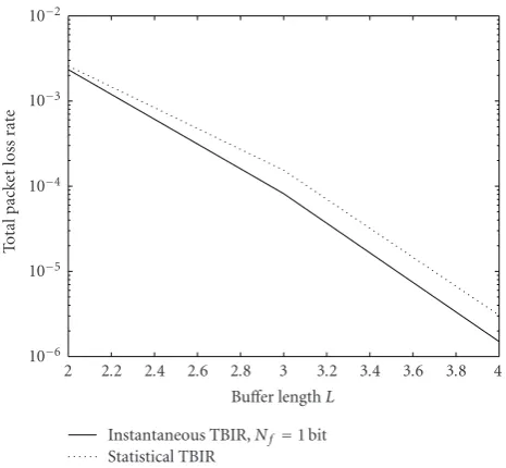
Instantaneous TBIR,Nf =1 bit Statistical TBIR
Figure6: Variation of average packet loss with buffer length for statistical TBIR (dotted lines) and one bit of instantaneous TBIR (solid lines) is shown.
Further, the packet loss versus SNR curve for (Nb=3, Nf = 0) intersects the curve for (Nb = 2,Nf = 1) at multiple points; this indicates that sometimes increasingNf by one bit reduces packet loss rates more than increasingNbby one bit. However, it should be mentioned that the goal here is to improve the system performance using the given FB bits, by adding FF bits. Moreover, we conjecture that for highly bursty sources (source having large variations in packets’ arrivals), the gain of 1 bit of FF would be higher than using an additional bit of FB. The question of whether adding an extra bit of FB is better than adding a bit of FF is challenging; the answer depends critically on the traffic arrivals and channel statistics and should be investigated carefully in future work.
Packet Loss Versus Buffer Length L. The variation of the total average packet loss with buffer length L is given in
Figure 6. It is clear that using 1 bit of FF can significantly reduce the average packet loss for the same number of FB bits. Note that for a delay of 1 time slot, the use of FF information does not reduce packet losses since packets cannot be delayed and the transmission rate cannot be adapted to channel conditions. This case is loosely analogous to the use of CSIT in discrete memoryless channels, in which CSIT does not increase capacity but could provide simpler methods to achieve capacity. However, for delays greater than 1 time slot, even though the source is a discrete memoryless source, the use of a buffer and greater flexibility in allowed delay introduces “memory” into the buffer state; thus, FF information provides performance gains (lower packet loss).
Table1: The power required to achieve a desired average packet error using a convolutional code with variable QAM.
No. of packets/time slot No. of bits/modulation symbol Average power (dB)
1 2 5.5
2 4 12
3 6 22.5
3 2.5 2
1.5 1
0.5 0
Number of feedback bitsNb 10−8
10−7
10−6
10−5
10−4
10−3
10−2
10−1
100
To
ta
l
p
ac
ke
t
lo
ss
ra
te
Instantaneous TBIR,Nf =1 bit Statistical TBIR
Figure7: Variation of average packet loss with number of feedback bits is shown for statistical TBIR (dotted lines) and one bit of instantaneous TBIR (solid lines).
earlier case, with one packet arrival on average, in every other time slot is considered. The loss rate with zero bits of CSIT is computed as follows. With no CSIT, power is transmitted at a constant rate (only depending on source arrivals). For this particular traffic, the transmission power is given by
Pno CSIT=(eR−1)/γno CSIT. From the given power constraint of P0, we can computeγno CSIT asγno CSIT = (eR−1)/2P0, where the factor of 2 comes from the fact that a packet is transmitted in only 50% of the time slots. The packet loss rate then equalsγno CSIT
0 e−x dx =1−e−γno CSIT. It can be seen fromFigure 7that even a few bits of FB and one bit of FF can provide significant gains in performance.
6.2. Implementation Strategies. In this paper, we have assumed that the transfer of FB and FF information takes place at the beginning of a time slot before data communi-cation in that time slot. It is also assumed that channel state information is available right at the beginning of the time slot. There are potentially many ways to implement these strategies; a couple of strategies are illustrated below.
(i) It is conceivable that CSI is computed at the receiver based on the reception of the FF information. Given that the FF information is likely to be only a few bits, accurate CSIR may be difficult to obtain. However, if pilot or synchronization bits are sent along with the
FF information, accurate CSI can be obtained from these bits.
(ii) In this paper, we assumed that the fading states in two different time slots are independent of each other. However, many practical communication systems exhibit considerable correlation in the fading process. This correlation can be used to obtain estimates of the CSI from prior time slots.
These strategies are pictorially depicted inFigure 4.
6.3. Practical Multirate System. Thus, the analysis so far in the paper is based on the information-theoretic concept of outage and transmission at rates close to Shannon capacity using finite block-length codes. We now demonstrate the application of FF information using a practical coding and modulation scheme. A similar coding and modulation scheme is used in [18] for multirate transmission over an AWGN channel.
We assume the size of each packet to be 25 bits, and the channel bandwidth and transmit pulse shape are such that 25 symbols can be transmitted in each time slot. The transmitter can choose to transmit 0, 1, 2, or 3 packets in each time slot. The data bits of all the packets in a time slot are jointly encoded, using a convolutional encoder of rate 1/2 with constraint length of 3 and generator matrix4 7[28]. The output of the convolutional encoder is modulated using a variable rate QAM depending onunaccording toTable 1. For example, to transmit 2 packets per time slot, the scheme needs to transmit 100 coded bits (2 packets×25 bits/packet
×2 coded bits/information bit) using 25 symbols, which implies 4 bits/symbol; hence we choose a simple rectangular 16-QAM constellation in this case. The power required to achieve a packet error rate of 0.02 is given inTable 1assuming instantaneousγn=1 (an alternative is to change the coding rate assuming that the modulation (number of constellation points) is fixed, say, 4-QAM; to transmit 1, 2, or 3 packets per time slot, coding rates of 1/6, 1/3, or 1/2 could be used, resp.) For other values ofγn, the power inTable 1should be scaled byγn.
13 12 11 10 9
8 7
Average power (dB) 10−2
10−1
100
To
ta
l
p
ac
ke
t
lo
ss
ra
te
Buffer length 3: FB=3 bits, FF=0 bit Buffer length 3: FB=2 bits, FF=1 bit Buffer length 3: FB=2 bits, FF=0 bit
Figure8: Variation of average packet loss with SNR for statistical TBIR and instantaneous TBIR with buffer lengthL=3.
the scheme with one additional bit of FB, that is,Nb=3 bits. Recognize that the packet loss hits an asymptote around 4% due to the design choice. Smaller values of the asymptote may be achieved by appropriately choosing a scheme with lower transmission packet error rate, that is,Πm,βi ≤ 0.02. However, such schemes require a higher transmit power and could result in performance degradation at small to medium SNRs. The optimal choice of operational frame error rate should be computed based on the SNR of interest. The results in this section are presented to merely indicate the feasibility of using the proposed scheme in a practical multirate system.
6.4. MIMO Systems. The proposed formulation directly extends to systems with MIMO architecture. For instance, in the special case of an MISO or SIMO system, the capacity [3] is given by 0.5 log(1 + (P/Nt)HtH/σ2), whereNt, N
rare the numbers of transmit and receive antennas andH is an
Nr×Ntmatrix of channel gains. The effective channel gain is thus a scalar given byHtHin the SIMO case (orHHtin the MISO case). The proposed formulation can be applied to this effective channel gain which has a Chi-squared distribution if the channels between the transmit and receive antennas are modeled as independent Gaussian. In the general MIMO case, theeffectivechannel gain would not be a scalar and one needs to optimize the feedback and feed-forward coefficients using a vector quantizer.
7. Conclusions
In this paper, we proposed a new communication system architecture in which information about transmit buffer is sent as feed-forward information to the receiver. This FF information is used in conjunction with the FB of channel state information to reduce average packet loss in
fading channels. Moreover, the proposed design framework provides a mechanism to provide delay guarantees to the arrival traffic.
We are currently working on studying the effects of FF for more realistic traffic arrival models. One limitation of the proposed scheme is the computational complexity of solving the optimization problems. It is likely that in practical systems the number of feedback bits will be limited to a small number (1–4 bits per coherence interval), and thus complexity is determined mainly by buffer lengthL. Con-ceptual extensions to frequency-selective fading channel are relatively straightforward using an orthogonal transmission scheme like OFDM; however, the complexity of the vector quantizer optimization that results needs to be investigated in future work. The impact of causal CSI knowledge along with errors in the FB and FF channels should also be considered carefully in future studies.
References
[1] T. M. Cover and J. A. Thomas,Elements of Information Theory, John Wiley & Sons, New York, NY, USA, 1991.
[2] A. J. Goldsmith and P. P. Varaiya, “Capacity of fading channels with channel side information,”IEEE Transactions on Information Theory, vol. 43, no. 6, pp. 1986–1992, 1997. [3] I. E. Telatar, “Capacity of multi-antenna Gaussian channels,”
European Transactions on Telecommunications, vol. 10, no. 6, pp. 585–595, 1999.
[4] M. Medard and A. Goldsmith, “Capacity of time-varying channels with channel side information at the sender and receiver,” in Proceedings of the International Conference on Communications (ICC ’99), pp. 20–16, Vancouver, Canada, June 1999.
[5] A. Lapidoth and S. Shamai, “Fading channels: how perfect need “perfect side information” be?” IEEE Transactions on Information Theory, vol. 48, no. 5, pp. 1118–1134, 2002. [6] M. M´edard, “The effect upon channel capacity in wireless
communications of perfect and imperfect knowledge of the channel,”IEEE Transactions on Information Theory, vol. 46, no. 3, pp. 933–946, 2000.
[7] E. Biglieri, J. Proakis, and S. Shamai, “Fading channels: information-theoretic and communications aspects,” IEEE Transactions on Information Theory, vol. 44, no. 6, pp. 2619– 2692, 1998.
[8] R. Gallager, “A perspective on multiaccess channels,” IEEE Transactions on Information Theory, vol. 31, no. 2, pp. 124– 142, 1985.
[9] A. Ephremides and B. Hajek, “Information theory and communication networks: an unconsummated union,”IEEE Transactions on Information Theory, vol. 44, no. 6, pp. 2416– 2434, 1998.
[10] A. Ephremides, “Some wireless networking problems with a theoretical conscience,” inCodes, Curves, and Signals: Common Threads in Communications, pp. 201–212, Kluwer Academic publishers, Dordrecht, The Netherlands, 1998.
[11] T. ElBatt and A. Ephremides, “Joint scheduling and power control for wireless ad-hoc networks,” inProceedings of the 21st Annual Joint Conference of the IEEE Computer and Communications Societies (INFOCOM ’02), vol. 2, pp. 976– 984, New York, NY, USA, June 2002.
Workshop on Multimedia Signal Processing (MMSP ’02), pp. 404–407, St. Thomas, Virgin Islands, USA, December 2002. [13] L. Tong, V. Naware, and P. Venkitasubramanian, “Signal
processing in random access: a cross-layer perspective,”IEEE Signal Processing Magazine, vol. 21, no. 5, pp. 29–39, 2004. [14] R. A. Berry and E. M. Yeh, “Cross-layer wireless resource
allocation,”IEEE Signal Processing Magazine, vol. 21, no. 5, pp. 59–68, 2004.
[15] S. Shakkottai, T. S. Rappaport, and P. C. Karlsson, “Cross-layer design for wireless networks,” IEEE Communications Magazine, vol. 41, no. 10, pp. 74–80, 2003.
[16] E. Shih, S.-H. Cho, N. Ickes, et al., “Physical layer driven pro-tocol and algorithm design for energy-efficient wireless sensor networks,” in Proceedings of the 7th Annual International Conference on Mobile Computing and Networking (MOBICOM ’01), pp. 272–287, Rome, Italy, July 2001.
[17] R. A. Berry and R. G. Gallager, “Communication over fading channels with delay constraints,”IEEE Transactions on Information Theory, vol. 48, no. 5, pp. 1135–1149, 2002. [18] D. Rajan, A. Sabharwal, and B. Aazhang, “Delay-bounded
packet scheduling of bursty traffic over wireless channels,”
IEEE Transactions on Information Theory, vol. 50, no. 1, pp. 125–144, 2004.
[19] B. E. Collins and R. L. Cruz, “Transmission policies for time varying channels with average delay constraints,” in Proceed-ings of the 37th Annual Allerton Conference on Communication, Control, and Computing, pp. 709–717, Monticello, Ill, USA, September 1999.
[20] R. Negi, Power adaptation strategies for delay constrained channels, Ph.D. thesis, Stanford University, Stanford, Calif, USA, September 2000.
[21] D. P. Bertsekas and R. Gallager,Data Networks, Prentice-Hall, Upper Saddle River, NJ, USA, 1992.
[22] L. H. Ozarow, S. Shamai, and A. D. Wyner, “Information theoretic considerations for cellular mobile radio,” IEEE Transactions on Vehicular Technology, vol. 43, no. 2, pp. 359– 378, 1994.
[23] D. Rajan,Power efficient transmission policies for multimedia
traffic over wireless channels, Ph.D. thesis, Rice University, Houston, Tex, USA, April 2002.
[24] A. Sabharwal, D. Rajan, and B. Aazhang, “Dual problems in power control,” in Proceedings of the 39th Annual Allerton Conference on Communication, Control and Computing, Mon-ticello, Ill, USA, October 2001.
[25] D. Rajan, A. Sabharwal, and B. Aazhang, “Outage behavior with delay and CSIT,” inProceedings of the IEEE International Conference on Communications (ICC ’04), vol. 1, pp. 578–582, Paris, France, June 2004.
[26] A. Gersho and R. M. Gray,Vector Quantization and Signal Compression, Kluwer Academic publishers, Dordrecht, The Netherlands, 1992.
[27] C. E. Shannon, “A mathematical theory of communication,”
Bell Systems Technical Journal, vol. 27, pp. 379–423, 1948. [28] J. G. Proakis,Digital Communications, Mc-Graw Hill, Boston,