Volume 2008, Article ID 373487,18pages doi:10.1155/2008/373487
Research Article
Implementational Aspects of the Contourlet Filter Bank and
Application in Image Coding
Truong T. Nguyen,1Yilong Liu,2Herv ´e Chauris,1and Soontorn Oraintara2
1Geophysical Research Center, Paris School of Mines, 35 Rue Saint-Honor´e, 77305 Fontainebleau, France
2Department of Electrical Engineering, University of Texas at Arlington, 416 Yates St. Arlington, Texas 76019, USA
Correspondence should be addressed to Truong T. Nguyen,[email protected]
Received 29 March 2008; Accepted 10 October 2008
Recommended by Wilfried Philips
This paper analyzed the implementational aspects of the contourlet filter bank (or the pyramidal directional filter bank (PDFB)), and considered its application in image coding. First, details of the binary tree-structured directional filter bank (DFB) are presented, including a modification to minimize the phase delay factor and necessary steps for handling rectangular images. The PDFB is viewed as an overcomplete filter bank, and the directional filters are expressed in terms of polyphase components of the pyramidal filter bank and the conventional DFB. The aliasing effect of the conventional DFB and the Laplacian pyramid to the directional filters is then considered, and the conditions for reducing this effect are presented. The new filters obtained by redesigning the PDFBs satisfying these requirements have much better frequency responses. A hybrid multiscale filter bank consisting of the PDFB at higher scales and the traditional maximally decimated wavelet filter bank at lower scales is constructed to provide a sparse image representation. A novel embedded image coding system based on the image decomposition and a morphological dilation algorithm is then presented. The coding algorithm efficiently clusters the significant coefficients using progressive morphological operations. Context models for arithmetic coding are designed to exploit the intraband dependency and the correlation existing among the neighboring directional subbands. Experimental results show that the proposed coding algorithm outperforms the current state-of-the-art wavelet-based coders, such as JPEG2000, for images with directional features.
Copyright © 2008 Truong T. Nguyen et al. This is an open access article distributed under the Creative Commons Attribution License, which permits unrestricted use, distribution, and reproduction in any medium, provided the original work is properly cited.
1. INTRODUCTION
Wavelet and filter bank (FB) have been one of major research topics in signal processing for the last two decades [1]. It is shown that the continuous wavelet functions and their associated regular FBs are optimal representations of one dimensional piecewise smooth signals [2]. However, the direct extension of wavelet to two dimensions by the tensor product of one dimensional wavelet is no longer optimal for image representation due to the intrinsic geometri-cal structure of typigeometri-cal natural images [3]. In short, the separable wavelets are still optimal in representing point discontinuities in a two-dimensional signal, but not eff ec-tive in capturing line discontinuities, which correspond to directional information in the image. Therefore, integrating geometric regularity in the image representation is a key challenge to improve the performances of current image coders.
Recently, Cand`es and Donoho constructed the curvelet transform [4], and proved that it is an essentially optimal representation of two variable functions, which are smooth except at discontinuities along C2 (twice differentiable)
curve. The nonlinear approximation of a function f, fM(c),
reconstructed byM curvelet coefficients has an asymptotic decay rate of f − fM(c)2 ≤ CM−2(log2M)
3
. This decay rate of the approximation error is a significant theoretical improvement compared to those by wavelet and Fourier coefficients, which areO(M−1) andO(M−1/2), respectively
[2]. Since the space of smooth functions with singularities along C2 curves is similar to that of natural images with
regions of continuous intensity and discontinuous along smooth curves (edges), there is a strong motivation for finding a similar transform in the discrete domain [3].
the Laplacian pyramid [6] and the conventional directional filter bank (DFB) [7]. It unites the advantages of both systems, which are multiresolution and multidirection. The authors also show that the contourlet transform can achieve the asymptotic optimal result as the curvelet transform. Essentially, these conditions assume that the directional filters have good passband and stopband characteristics in the Fourier domain.
The contourlet transform and its associated FB has been an active subject of research in recent years [8–12]. However, there has been no comprehensive work on the detail implementation of the FB and its application in image coding.
Because of its effectiveness in representing natural image, the PDFB has been used in image coding recently [13–
16]. These works, however, are based on the original implementation of the PDFB [5], which contains aliasing in the directional filters. Therefore, the achieved coding results are not comparable to state-of-the-art wavelet-based coders, such as JPEG2000.
The contribution of this work is as follows. First, we provide detail explanations of the DFB tree as it is implemented in the contourlet FB [17]. Moreover, the structure is modified to minimize the phase delay of the DFB basis. We also demonstrate how to handle size-limited images along the DFB tree and the effect of the binary tree on the frequency supports of the DFB directional filters. Our second contribution is to demonstrate several aliasing problems of the DFB tree and the PDFB. It is shown that some of these aliasing problems can be attenuated by changing the design criteria of the filters in the Laplacian pyramid of the PDFB. Finally, a novel embedded image coding system based on the image decom-position and a morphological dilation algorithm are pre-sented. Experimental results show that the proposed coding algorithm outperforms the current state-of-the-art wavelet-based coders, such as JPEG2000, for images with directional features.
1.1. Notations and paper outline
Here, we briefly review the notations and terminology used in 2-D multirate system. For fundamental operations in multidimensional 2-D systems, we refer to [18].
(i) Uppercase and lowercase bold face letters repre-sent 2 × 2 square matrices and 2 × 1 column vectors, respectively. For example, h(n) is a function defined on the 2-D integer lattice (n1,n2)T, and π is (π,π)T. Bold letters variables are employed frequently to compress math-ematical expressions. For example, H(ω) is the same as
H(ω1,ω2).
(ii) The superscriptsT and−T denote the transpose, transpose of the inverse, respectively.
(iii)N(M) is defined as the set of integer vectors of the formMx, wherex∈[0, 1)2.|M|represents the determinant of the matrixM. The number of elements inN(M) is equal to|M|.
(iv) The Fourier transform of a 2-D filterh(n) is defined as
H(ω)= n∈Z2
h(n)e−jωTn
, whereω=ω1,ω2T. (1)
(v)Matrix exponential notations greatly simplify 2-D multirate system expressions. The notationzMis defined as
zMzm11
1 zm221,zm112zm222
T
, whereM=
m11 m12 m21 m22 . (2)
Therefore, H(ωM) = H(MTω) = H(m11ω1 +m21ω2, m12ω1+m22ω2).
The following matrices are used to decimate subband images in the PDFB:
Q0=
1 −1
1 1
, Q1=
1 1
−1 1
, R0=
1 1 0 1
,
R1=
1 −1
0 1
, R2=
1 0
−1 1
,
R3=
1 0 1 1
, D0=
2 0 0 1
,
D1=
1 0 0 2
, D2=
2 0 0 2
=2I.
(3)
Paper outline
The DFB is analyzed in detail in Section 2. We first show how the DFB tree can be implemented by a binary-tree structure, as in [5,7,19]. The tree structure is then modified by adding delay and advanced blocks at appropriate places to make sure that the phase delays of the overall directional filters in the DFB tree are minimized. We also show how rectangular images are handled along the tree structure. In
Section 3, the PDFB is viewed as an overcomplete FB, and the equivalent directional filters are expressed in terms of the polyphase components. The aliasing problems existing in the PDFB structure are analyzed in Section 3.1, where it is shown that most of the aliasing can be removed if the two lowpass filters employed in the pyramid satisfy the Nyquist criteria. Discussion and simulations in Section 3.2
demonstrate the improvement of the PDFB with new design conditions. In Section 4, we describe a novel embedded image coding scheme based on the image decomposition obtained by a combination of PDFB and wavelet filter bank. The morphological operation is employed progressively to identify clusters of significant coefficients in each bit plane. Context-based arithmetic coding is used to encode these significant coefficients. We design the context models so that the intraband and interband correlations of the overcomplete PDFB can be well exploited. The coding results and discussions are presented inSection 4.4.Section 5
2. ITERATIVE TREE STRUCTURE FOR THE DIRECTIONAL FILTER BANK
The DFB is a 2n-band maximally decimated, perfect
recon-struction (PR) FB introduced by Bamberger and Smith in [7]. The original construction of an eight-band DFB, whose frequency partitioning whenn=2 (or 3) is inFigure 1, uses a two-level (or three-level) binary tree of two-channel FBs. The construction is not easy to generalize to 2n-band DFB,n >3,
since two-channel FBs with different passband supports are needed at different levels of the tree. A new construction of the DFB tree is proposed in [22]; its implementation is included in the contourlet toolbox [5]. Figure 2illustrates this new implementation of the DFB for the casenup to 3.
In order to explain the DFB tree inFigure 2, we need to define four matrices Pi, i = 0, 1, 2, 3 from the previously
defined matrices. The following matrix identities can be easily checked:
P0=R0Q0=D0R3, P1=R1Q1=D0R2, (4) P2=R2Q0=D1R1, P3=R3Q1=D1R0, (5)
RiDn1=Dn1R2
n
i , i=0, 1, RiDn0=Dn0R2
n
i , i=2, 3,
(6) Q0Q1=2I, R0R1=R2R3=I. (7)
An unimodular matrix is a matrix with determinant equal to±1. A resampling matrix is an unimodular matrix having integer elements. The matrices Ri, i = 0,. . ., 3, as well as
Sni, n = 3, i = 1,. . ., 2n, at the end of the DFB tree are
resampling matrices. The exact values ofSni are later defined
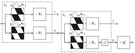
in (10) and (11). When an image is down- or upsampled by a resampling matrix, its pixels are simply reorganized (or the image is resampled). For example, the rectangular image with white line border in Figure 8(b) can be obtained by downsampling the corresponding image inFigure 8(a) byR3.
The DFB binary tree inFigure 2is constructed by using fan FBs. However, these fan FBs use different decimation matrices. In the first level, the fan FB uses the decimation matrix Q0; the two fan FBs at the second level use the
decimation matrix Q1. If we switch the decimation block Q0 at the first level and the fan FBs at the second level
and apply multirate FB theory, it is straightforward to show that the overall filters have frequency supports as depicted inFigure 1(a) and the decimation ratios of all four output bands are 2I. The expressions for these four directional filters from fan filtersH0(f)(z) andH
(f)
1 (z) are in (12)–(15).
Beginning from the third level, four types of resampled fan FBs referred to as F0,F1,F2, and F3 are used. The positions of these four resampled fan FBs at the third level of the DFB tree are illustrated in Figure 2. Each of these fan FBs has two outputs: 0 and 1. We call them resampled fan FBs because the input ofFi is resampled by
the unimodular matrixRibefore entering the fan filters. If we
switch the resampling matrices and the fan filters, the shape of the equivalent frequency response of the fan filter will be parallelograms, as demonstrated inFigure 3.
One can obtain a 2n+1-band DFB from the tree structure
of the 2n-band DFB by appending fan FB’sF2
k+p at outputs
p ofF2k andF2k+1 of thenth level, wherek,p = 0, 1. This
iterative division of the frequency plane to produce finer direction can be explained as follows. Let us consider the first subband (number 0) of a four-band DFB, which is denoted as x(n). This signal is also the input of a fan FB of type
F0 to obtain eight-band DFB (Figure 2). Since the outputs of a four-band DFB are decimated by 2I, the frequency of the subband 0 in Figure 1(a) is magnified by 2 in both ω1
andω2directions, as illustrated inFigure 4(a). The frequency regions that correspond to band 0 and 1 in an eight-band DFB (Figure 1(b)) are mapped to the two darker and the two lighter regions, respectively. On the other hand, by switching the resampling block R0 and the fan filters, the effective
support of the fan FB typeF0 has parallelogram shapes as illustrated inFigure 3. One can see that indeed the two fan filters in fan FB typeF0inFigure 3separate subband 0 and subband 1 of an eight-band DFB.
Following multirate signal processing theory, when the signalx(n) is decimated byP0, the frequency content ofX(ω)
is mapped to the support ofX(P−0Tω) (Figure 4(b)). By the
observation of the two Figures3(b) and4, we can see that in order to obtain a sixteen-band DFB from eight-band DFB, we need to attach fan FB typeF0andF1on the two outputs of the FB typeF0at the third level of the DFB tree.
In order to determine the subband number at the output of the resampled fan FBsFifor a 2n-band DFB (n≥3), we
only have to follow the path of the subband in the binary tree and collect the output number at each level of the tree. Then -digit number is the binary form of the subband number (see
Figure 2for the case of an eight-band DFB). The numbering of directional subbands in 2n-band DFB has to start from 0,
beginning from the left to right, top to bottom, as depicted inFigure 1.
After iteratively cascading fan FBs to create an n-level tree for a 2n-band DFB, the equivalent decimation matrices
for each subband will not be the same. By following the above cascading rule, the overall decimation matrix can be determined. For example, the subbandiin the 2n-band DFB
whose binary representation is i = m1m2· · ·mn has the
following overall decimation matrix:
Pn i = ⎧ ⎪ ⎪ ⎪ ⎪ ⎪ ⎪ ⎨ ⎪ ⎪ ⎪ ⎪ ⎪ ⎪ ⎩
Q0Q1 n−1
j=2
Pmj, 0≤i <2n−1,
Q0Q1 n−1
j=2
P(mj+2), 2
n−1≤i <2n,
(8)
where Pi’s are defined in (4) and (5). Using the matrix
identities from (4) to (7), we can further simplify the overall decimation matrices as
Pni =D2 n−1
j=2
D0R(3−mj)=diag
2(n−1), 2
n−1
j=2
R2(3(n−−mj−1)j), (9) for 0 ≤ i < 2n−1. The final step of the analysis FB is to
resample subbands by backsampling matricesSni to make the
overall decimation matrix diagonal:
Sni =
n−1
j=2 R2(3(n−−mj−1)j)
−1 =
n−1
j=2
0
0 1
1
2
2 3
3
ω2
ω1 (π,π)
(−π,−π)
(a)
0
0 1
1 2
2
3
3 4
4 5 5
6
6 7
7
ω2
ω1 (π,π)
(−π,−π)
(b)
Figure1: Frequency divisions of the conventional DFB [7] in case of (a) four-channel DFB and (b) eight-channel DFB.
First level
H0(f)
↓Q0
H1(f)
↓Q0
Second level
H(0f)
↓Q1 0
H(1f)
↓Q1 0
1
H(0f)
↓Q1 1
1
H(1f)
↓Q1 0
z1
Third level
F0
H0(f)
↓R0 ↓Q0
1
↓S31 1
↓R0
H1(f)
↓Q0 0 ↓S30 0
F1 H
(f) 0
↓R1 ↓Q1 0 ↓S32 2
H1(f)
↓R1 ↓Q1
1
↓S33 3
F3 H
(f) 0
↓R3 ↓Q1 1 ↓S37 7
H1(f)
↓R3 ↓Q1 0 ↓S36 6
F2 H
(f) 0
↓R2 ↓Q0 0 ↓S34 4
H1(f)
↓R2 ↓Q0 1 ↓S35 5
F0 H (f) 0 (ω)
↓R0 ↓Q0 1
↓R0
H(1f)(ω)
↓Q0 zd2 0
F1 H
(f) 0 (ω)
↓R1 ↓Q1 0
H(1f)(ω)
↓R1 ↓Q1 zd2 1
(a)
F0 H (f) 0
ωR0
↓P0 1
H1(f)
ωR0
↓P0 z2d 0
F1 H0(f)
ωR1
↓P1 0
H1(f)
ωR1
↓P1 zd1 1
(b)
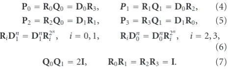
Figure3: Resampled fan FBs of typesF0 andF1used after level two of the binary DFB tree: (a) original structures and (b) equivalent
structures obtained by switching the resampling blocks and the filtersHi(f).
ω2
ω1 (π,π)
(−π,−π)
X(ω1,ω2)
(a)
ω2
ω1 (π,π)
(−π,−π)
X(0.5ω1−0.5ω2,ω2)
(b)
Figure4: Illustration of frequency mapping when a 2-D signalX(ω) is downsampled byP0, (a)X(ω) is the subband 0 in a four-band DFB
inFigure 1(a) decimated by 2I, (b) the support ofX(P−T 0 ω).
By similar derivation, one can show that the backsampling matrices for subbandi, 2n−1≤i <2nare
Sni = n−1
j=2
R2m(nj−j−1). (11)
The process in the synthesis tree is exactly the reverse of the analysis side.
2.1. Phase correction in the DFB tree
Although the construction of the DFB using iterative fan FB described above has many advantages, it also has one potential problem. Typically, the two prototype fan filters are linear phase with different phase delay. However, the resampling blocks in the tree further deviate the overall phase delay of the directional filters. In processing a size-limited image, periodic or symmetric extension is used to obtain PR without introducing additional samples. If symmetric
extension is used in the DFB tree, the phase delay at each level should be less than the overall decimation ratio. For example, if the phase delay of a particular subband filter at levelnis larger than the decimation ratio of that subband, then the subband image will have an artificial border inside the image. As a result, the two subband images at leveln+1 coming from that subband will have large areas of border artifacts.
2.1.1. Phase correction in the four-band DFB tree
In order to reduce the phase difference of these linear-phase filters at each level of the tree, delay and advance blocks are inserted at appropriate branches. In order to simplify our discussion, let us assume that the first fan filterH0(f)(z) used
in the tree in Figure 2is zero phase, and the second filter has a phase factor of e−jω1, which means that H(f)
1 (z) = z−1
1 H (f)
1r (z), where the subscription r of any filter in this
that the corresponding frequency response is real. Available methods for designing PR linear-phase fan FBs satisfying the condition above can be found in many previous works such as [23–25], and will not be discussed here. At the second level of the tree, the equivalent frequency responses of the four directional filters are
H0(ω)=H0(f)(ω)H (f) 0
ωQ0=:H0
r(ω), (12)
H1(ω)=H0(f)(ω)H (f) 1
ωQ0=:e−j(ω1+ω2)H1
r(ω), (13) H2(ω)=H1(f)(ω)H
(f) 0
ωQ0=:e−jω1H2
r(ω), (14) H3(ω)=H1(f)(ω)H
(f) 1
ωQ0=:e−j(2ω1+ω2)H3
r(ω). (15)
Since the equivalent decimation matrix of these filters is Q0Q1=2I, the delays of the filter inn1andn2directions can
be kept less than the decimation ratios in those directions. In this case, the decimation ratios inn1 andn2 are two. Since the delay factor inH3(ω) isz−2
1 z−21, an advance block z1 is
inserted at its output as inFigure 2.
2.1.2. Phase correction in the2n-band DFB tree
As mentioned earlier, four types of resampled FBs (F0,F1,
F2, and F3) are used starting from level three of the tree (Figure 2). Using the noble identities [18], switching the resampling block and the fan filter in type Fi results in a
filter whose frequency response is of parallelogram shape with corresponding decimation matrixPi as defined in (4)
and (5). Figures3(a) and3(b), respectively, show examples of the FBs before and after switching for typesF0andF1. It can be shown that the overall decimation matrices starting from level three to the end of the tree including the backsampling matricesSni areDn0−2 for subbands 0 to 2n−1−1 andDn1−2
for subbands 2n−1to 2n−1. Therefore, the task of the delay
block is to keep the distance between the center of symmetry of the filter and that of the directional filter at level two less than (2n−2, 1) for the first half, and (1, 2n−2) for the second half of the tree. For example, the subband 0 of a 16-band DFB can be obtained by cascading the resampled fan FB of typeF0to output 0 of the eight-band DFB inFigure 2(before the backsampling matrixS3
0), as shown inFigure 5. Hence,
the equivalent filterH2−4
0 (z) (the superscript 2−4 represents
transition from level two to level four of the tree) for output 0 can be expressed in terms of the prototype filterH1(f)(z) as
H2−4 0 (z)=H
(f) 1
zR0H(f)
1
zP0R0. (16)
Since the phase factor ofH1(f)(z) ise−jω1, the phase factors
of H1(f)(zR0) and H (f)
1 (zP0R0) are e−jω1 and e−j(2ω1+ω2),
respectively. Hence, the phase factor ofH02−4(z) ise−j(3ω1+ω2).
Since the equivalent decimation matrix of this path isD20 =
diag(4, 1) in order to keep the center of symmetry in the range (4−1), an advance block zd2 withd = 1 is inserted
before the backsampling matrixS40as illustrated inFigure 5.
Following similar analysis, it can be shown that for an n-level tree DFB with n ≥ 4 in order for the overall directional filters to have their centers of symmetry within the decimation ratios, a delay block zd2 with d = ±2(n−4)
must be added to the resampled fan FBs of types F0 and
F1 at level n ≥ 4, as depicted inFigure 3. The value of d
is positive for subbands 0, 1,. . ., 2n−2 −1 and negative for subbands 2n−2,. . ., 2n−1−1.
For the cases of resampled fan FBs of typesF2 andF3, we assume that the first fan filterH0(f)(z) is zero phase and
the second fan filter H1(f)(z) has a phase factor of e−jω2.
Therefore, a delay blockzd1 withd= ±2(n−4)must be added
to the resampled fan FBs of typesF2andF3at leveln ≥ 4. The value ofdis negative for subbands 2n−1,. . ., 3×2n−2−1
and positive for subbands 3×2n−2,. . ., 2n−1.
In order to demonstrate the effect of phase correction, we display six basis functions of the contourlet FB without and with phase correction inFigure 6. The six basis functions are chosen to be more vertical to demonstrate horizontal shift, and created by setting a coefficient of each selected subband to one and all others to zero. The positions of these six coefficients are in the same row and equally spaced in columns. Hence, the ideal reconstruction would contain six directional impulse responses nearly equally spaced in horizontal direction (they will be exact if all filters are zero phase). The upper and lower images in Figure 6 are the reconstructions of the PDFB without and with phase correction, respectively. We can see that without phase correction, the centers of the six basis functions are shifted (from the vertical dotted lines). This is minimized when phase correction is applied. This property is very important when one would like to take advantage of the interscale and inter-band relationship between coefficients at the same location [26].
2.2. Processing size-limited images along the DFB tree
One problem related to the implementation of the DFB that so far has not received sufficient attention in the literature is how to handle border extension of size-limited images so that the transform by DFB is PR and nonexpansive. Two methods that permit such critical representation are periodic extension and symmetric extension. Generally, the boundary reflection method is preferred over periodic extension because the periodic extension method creates artificial edges at the border of the image. However, mirror-symmetry extension is not possible for the DFB. This is because mirror-symmetry extension requires that the 2-D filters to be symmetric through vertical and horizontal axes (or quadrantally 2-D symmetric [27]), which is not possible for fan filters. Therefore, in this section, we consider only periodic extension for the DFB tree.
Let us assume that the input image to the DFB tree in
Figure 2 is of a rectangular size N ×M, where N andM
are even numbers. When being convolved withHi(f)(z), i=
0, 1 at the first level of DFB tree, the image is periodically extended. When the convolved images are decimated byQ0,
the resulting images will have rectangular shapes rotated by 45◦. These rotated rectangular images are not easy to store and process at the second level of the DFB tree. Instead, after decimation of the convolved images byQ0, we can keep only
F0 H0(f)
ωR0
↓P0 1
H1(f)
ωR0
↓P0 0
F0 H0(f)
ωR0
↓P0 1
H1(f)ωR0
↓P0 z2d 0
↓S40
Figure5: Subband 0 of the 16-band DFB. The figure shows the path (bold line) from level two to level four with corresponding transfer
functionH2−4 0 (z).
Figure 6: Six contourlet basis functions created by the PDFB
without phase correction (upper part) and with phase correction (lower part).
operation is best explained by an example. The Boat image in the rectangular region with white line border inFigure 7(a) is of size 200×300. After downsampling byQ0, the rectangular
image that we need to keep is of size 150 ×250, in the rectangular region with white line border inFigure 7(b).
At the second stage of the tree, we need to pay special attention to border extension of the two outputs of the first level. We cannot use periodic extension because it will lead to disturbing border artifact along diagonal line at the center of reconstructed images. Instead, we have to extend the two rectangular subband images in such a way that the periodic extensions at the first level of the DFB tree are preserved. This extension is illustrated inFigure 7(b), where the rectangular image inside the dotted line is the extended images in the second level of the DFB tree.
The decimation ratio for the first two levels of the DFB tree is 2I, the size of subband images enters fan FB Fi in Figure 2 is of size M/2×N/2. Beginning from the third level of the tree, the decimation ratio of the fan FBFiisPi,
which can be interpreted as a downsampling by 2 in row (or column), followed by a resampling operation. The resampled
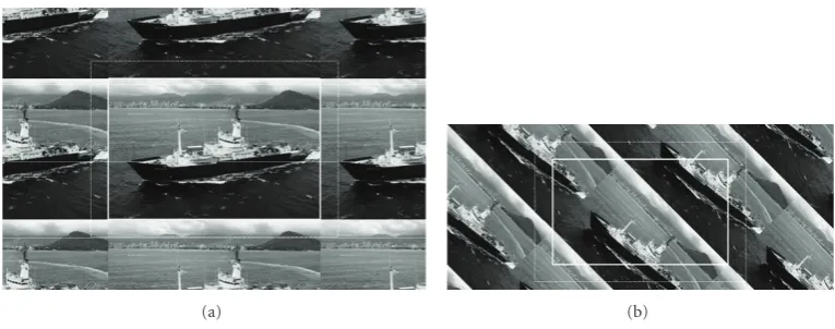
images need to be parallelogram periodically extended so that there are no new borders at the extension area around the rectangular subband images.Figure 8contains the Boat image downsampling byD0 and downsampling byP0. The
image inFigure 8(a) is periodically extended, but the image inFigure 8(b) is parallelogram periodically extended.
2.3. Aliasing on the binary tree of the conventional DFB
The conventional DFB realized by a binary tree of maximally decimated two-channel FBs [7] is very efficient. However, it also leads to aliasing problems to the overall directional filters, which can be divided into two types: highpass aliasing and stopband aliasing components. FromFigure 2, one can see that the DFB tree needs only one prototype fan FB [19]. Following the path to obtain subband 0 of an eight-band DFB (Figure 1(b)) in the DFB tree in Figure 2 and using noble identities of multirate system theory [18], we can move all the decimation blocks to the right-hand side, after all the filtering blocks. The directional filter corresponds to subband 0 in the DFB tree is given by
H0ω1,ω2=H0(f)(ω)H (f) 0
ωQ0H(f)
1
ω2R0
=H0(f)
ω1,ω2H0(f)
ω1+ω2,−ω1+ω2
×H1(f)
2ω1, 2ω1+ω2,
(17)
(a) (b)
Figure7: Boat image of size 200×300 (a) periodic extension of the original image and (b) after downsample byQ0.
(a) (b)
Figure8: Boat image obtained from the original image of size 100×300 with periodic extension by downsampling using matrices (a)D0
and (b)P0.
not very strong, but still visible (see the leftmost image in
Figure 16(b)).
This highpass aliasing problem is more pronounced in the directional filters of the second resolution of the PDFB if the lowpass filter of the Laplacian pyramid in the PDFB does not satisfy the Nyquist criterion with respect to decimation matrix D2, that is, if its passband and transition band are
not restricted within [−π/2,π/2]2. This condition will be discussed inSection 3. The equivalent directional filters of the PDFB in [5] at the second level of the pyramid are plotted inFigure 9(c), where the aliasing at high frequency is displayed very clearly.
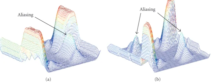
The stopband aliasing problem of the DFB will appear when the number of directional bands increases. The frequency responses of the directional filters will have some peaks in the stopband regions. This is because when more fan filters with decimation blocks are cascaded, their transition bands will overlap. The two aliasing problems of the directional filters generated by the DFB tree are illustrated inFigure 10.
3. THE PYRAMIDAL DFB FOR THE CONTOURLET TRANSFORM
The PDFB (or contourlet FB) is created by combining the Laplacian pyramid and the DFB with 2n orientational
subbands [5]. It is shown in this section that the combination of a Laplacian pyramid and a four-band DFB is equivalent to an overcomplete five-band FB. Let us denote the two two-dimensional lowpass filters in the Laplacian pyramid in
Figure 11asG(z) andF(z). The first filter can be written in type I polyphase form as follows:
G(z)=G(0)zD2+z−1
1 G(1)
zD2
+z−1 2 G(2)
zD2+z−1
1 z−21G(3)
zD2
=gTzD2e(z),
(18)
whereg(z)=[G(0)(z),G(1)(z),G(2)(z),G(3)(z)]T, ande(z)=
[1,z−1
1 ,z−21,z1−1z−21]T. Similarly, letf(z) be the column matrix
of the (type II) polyphase components of the interpolation filterF(z), that is,
F(z)=F(0)zD2+z1F(1)zD2 +z2F(2)zD2+z1z2F(3)zD2
=fTzD2ez−1.
(19)
The detailed output of the Laplacian pyramid is denoted as
d(n) in Figure 11(a). If one considers the four polyphase components ofd(n) as the four outputs of an FB with input
x(n) then it can be shown that the polyphase matrix of that FB isI−f(z)gT(z).
In the PDFB depicted inFigure 11(a), a four-band DFB is applied to the detailed signald(n). LetE(z) be the polyphase matrix of the four directional filters of the four-band DFB, as defined in (12)–(15), that is,
H1(z),H2(z),H3(z),H4(z)T =EzD2e(z), (20)
where e(z) = [1,z−1
1 ,z−21,z−11z2−1]T. The input x(n) goes
H0(f)(ω1,ω2) H1(f)(2ω1, 2(ω1+ω2))
H0(f)(ω1+ω2,−ω1+ω2)
↓4 00 2
(a)
ω2
ω1 (π,π)
(−π,−π)
(0, 0)
(b)
ω2
ω1 (π,π)
(−π,−π)
(0, 0)
−π
2 π2
(c)
Figure9: Aliasing effect on DFBs obtained by using the tree structure: (a) the equivalent structure to obtain subband 0 in eight-band
DFB structure inFigure 2, (b) the equivalent directional filterH0(ω1,ω2). Black, gray and white colors denote passband, transition band, and stopband, respectively, and (c) an example of the amplitude of frequency response of a contourlet basis at the second resolution level, displayed as a gray-scale image.
(a)
Stopband aliasing
High frequency aliasing
(b)
Figure10: The frequency responses of (a) a fan filter with very small transition band, and (b) the directional band of a sixteen-band DFB
created from the fan filter of (a).
produce four subsampled outputs yi(n),i = 1, 2, 3, and 4.
These four signals can be considered as the outputs of the analysis side of an FB with inputx(n), and it can be shown that the polyphase matrix of this overall FB isE(z)=E(z)(I−
f(z)gT(z)).
Therefore, the PDFB inFigure 11(a) is equivalent to the five-band analysis FB inFigure 11(b) with the same lowpass filterG(z) and four directional filtersHi(z) which are given
as
H1(z),H2 (z),H3 (z),H4 (z)T=EzD2e(z). (21)
3.1. Aliasing effect of the Laplacian pyramid
In order for the PDFB to achieve its potential performance, it is necessary that the equivalent directional filters have excellent frequency responses. In general, the construction of the PDFB consists of a separable Laplacian pyramid and a binary-tree conventional DFB [7]. Thus, there are two sources of aliasing that will be considered in this section: those on the DFB tree, and those caused by the pyramid structure.
The equivalent directional filters Hi(z) in (21) can be
x(n)
G
↓D2
↑D2
F
− + d(n)
H1
H2
H3
H4
↓D2
↓D2
↓D2
↓D2
y0(n)
y1(n)
y2(n)
y3(n)
y4(n)
(a)
x(n)
G
H1
H2
H3
H4
↓D2
↓D2
↓D2
↓D2
↓D2
y0(n)
y1(n)
y2(n)
y3(n)
y4(n) (b)
Figure11: The four-band PDFB (a) the analysis side of the PDFB, (b) equivalent overcomplete FB, and (c) the synthesis FB.
Aliasing
(a)
Aliasing
(b)
Figure12: Examples of equivalent directional filters in the PDFB (a) the equivalent filterH1(ω1,ω2) of four-band PDFB, (b) a directional
filter of eight-band PDFB, function associated with filterH1(z).
the PDFB constructed using the “9-7” biorthogonal filters as the lowpass filters G(z) and F(z) as in [5]. The fan FBs in the DFB tree structure are implemented using the ladder structure (with filter lengths of 21 and 41) in [23]. The first directional filter for the case of four-band DFB is plotted in
Figure 12(a). It is observed that the directional filters have “bumps” in the stopband region. Similarly, an eight-band DFB can be obtained by cascading one more step of two-channel filter banks at the binary tree. Its first directional filter is presented inFigure 12(b) showing more bumps in the stopband. It will be shown later that this effect is due to aliasing resulting from decimation and interpolation of the Laplacian pyramid, and the heights of these peaks are independent from the directional filters in the DFB.
LetFH1(z)=F(z)H1(z) be written in a polyphase form as
FH1(z)=FH1(0)
zD2+z−1
1 FH (1) 1
zD2
+z−1 2 FH
(2) 1
zD2+z−1
1 z2−1FH (3) 1
zD2, (22)
whereFH1(i)(z)is the polyphase components of FH1(z). By
some manipulation, it can be shown that the block diagrams in Figures14(a) and14(b) are equivalent, whereFH1(0)(z) is
the first polyphase component ofFH1(z). Consider the signal
y1(n) in Figure 11(a). The corresponding block diagram
can be redrawn as inFigure 13(a), where the subsystem in the dotted rectangle is equivalent to FH1(0)(z). Using the
noble identities, the top path inFigure 13(a) can be further simplified as inFigure 13(b).
Since the PDFB is realized by FIR filters, the filters are not ideal, their frequency responses have transition bands.
Figure 15(a) shows the passband support of FH1(z). The resulting filter FH1(0)(zD2) in Figure 13(b) is obtained by
downsampling followed by upsampling the filter FH1(z) byD2. The corresponding frequency responseFH1(0)(DT2ω)
whose supports are displayed inFigure 15(b) can be given by
FH1(0)
DT2ω
= 1
D2
k∈N(DT 2)
FH1ω−2πD−2Tk
. (23)
Therefore,
H1(ω)=H1(ω)−1
D2G
(ω)
× k∈N(DT
2)
Fω−2πD−T 2 k
H1ω−2πD−T 2 k
.
(24)
FH1(0)(ω)
x(n)
G(ω)
↓D2 ↑D2
F(ω) H1(ω)
↓D2 − +
y1(n)
↓D2
H1(ω) (a)
FH1(0)(DT2ω)
x(n)
G(ω)
↓D2 −
+
y1(n)
↓D2
H1
(b)
Figure13: The equivalent structure to the directional filterH1 (ω1,ω2) in the four-band PDFB inFigure 11.
↓D2 ↑D2 FH1(z)
(a)
FH1(0)(z) (b)
Figure14: Equivalent block diagrams.
summation can be neglected, and the overall filterH1 (ω) can be approximated by
H1ω1,ω2≈H1ω1,ω2
1−1
D2
Gω1,ω2Fω1,ω2
−1
D2G
ω1,ω2)Fω1,ω2−πH1ω1,ω2−π.
(25)
The second term in (25) produces the peaks in stopband of
H1(ω) (seeFigure 12). The positions of these peaks are in the passband of the modulated directional filterH1(ω1,ω2−π), so the only way to eliminate these “bumps” is to reduce the overlapping transition bands between G(ω1,ω2) and
F(ω1,ω2−π). Since bothG(z) andF(z) are lowpass, and if the Nyquist sampling condition is satisfied, the above aliasing term will be cancelled. Therefore, the two filters in the Laplacian pyramid should satisfy the following conditions:
Gω1,ω2≈0, Fω1,ω2≈0
whenω1>π
2 or ω2>
π
2.
(26)
This means that the cutofffrequency ofG(z) andF(z) must be a little less thanπ/2 in order to keep approximately zero response beyondπ/2. For convenience, we call the conven-tional PDFB (with cutofffrequency at π/2)aliasingPDFB,
and the one satisfying the above constraints nonaliasing PDFB.
Recently, a new contourlet FB is presented in [28]. The new FB replaced the Laplacian pyramid by a multireso-lution FB implemented in frequency domain. This new construction of contourlet FB removed the aliasing problems by requiring the lowpass filters to have frequency support strictly restricted in [−π/2,π/2]2 region. In order for the new contourlet FB to be PR, its multiresolution FB has to be implemented in frequency domain, which implies periodic extension for size-limited images. This will lead to border artifact problem for image coding application.
3.2. Reduced aliasing pyramidal directional filter bank
In order to demonstrate the aliasing effect from the direc-tional filters in the PDFB, the impulse responses of the overall directional filters at different scales are compared in
(a) (b)
Figure15: The frequency supports of (a)FH1(ω) and (b)FH1(0)(DT2ω).
realized by a binary tree of two-channel fan FBs, which are implemented by a two-step ladder structure [23]. Both decompositions have 32, 16, 8, and 4 directional subbands at the first, second, third, and fourth resolutions, respectively, as displayed in Figure 16. It is evident that the filters in
Figure 16(c) have much less aliasing and better directionality than those inFigure 16(b).
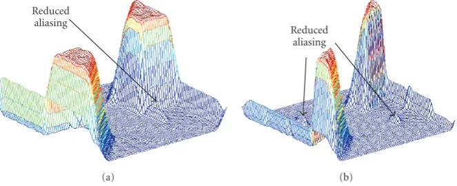
In practice, most of the unwanted aliasing components considered in the previous section can be reduced if the two lowpass filters in the pyramid have slightly smaller passband. Figures 17(a) and 17(b) show examples of the frequency responses of the first directional filters of the four-band and eight-band PDFBs whoseF(z) andG(z) are designed to have a transition band 0.3π < |ωi| < 0.6π. Comparing to the frequency responses presented in Figures 12(a) and 12(b), it is clear that those aliasing bumps have been significantly suppressed.
4. IMAGE CODING USING HYBRID OVERCOMPLETE PDFB AND WAVELET FB
Although the equivalent directional filters of the PDFB (or contourlet basis) are efficient in representing image contours, its performance tends to be lower than that of the traditional discrete wavelet transform (DWT) when the image sizes get smaller. In our nonlinear approximation experiment [20] with typical testing images (Lena and Barbara), the best results are achieved when the PDFB is used at higher resolution, and the DWT is used when the image sizes are less than or equal to 128×128. For the image coding application in this paper, we use a five-level image decomposition: the PDFB is used at the highest two resolutions, and the DWT is used in the next three resolutions.Figure 18(a) depicts the frequency supports of the hybrid FB. The Barbara image and its decomposition by the hybrid FB are illustrated in Figures
18(b) and18(c), respectively.
Since significant coefficients of the PDFB are sparser than those of wavelet, utilizing the statistical properties of the transform coefficients is a crucial task in the design of high-performance PDFB-based coders. An explicit way to solve this problem is to classify the coefficients of each subband
into two subsets that separate insignificant and significant coefficients. Thus, the quantization and estimated models can be adapted to each subset independently.
A potential approach to exploit this behavior has been introduced with the morphological operation for wavelet coding [29]. Based on the observation that clusters tend to grow in both spatial and frequency domain, the previ-ously detected significant coefficients are used as seeds for the search of new significant ones. The clustering trend of significant coefficients also exists in the PDFB bands. This suggests using a morphological dilation to identify the significant coefficients in the PDFB subbands before the coding step. Thus, different probability models can be estimated for significant and insignificant coefficients separately. On the other hand, although the overcomplete transform introduces more coefficients to be coded, strong correlations exist between neighboring directional subbands that can be adopted to improve probability modeling.
4.1. Progressive morphological dilation
Dilation is a morphological operator frequently adopted [30]. LetI be a binary-valued image where dilation will be applied. Dilation of a given setA⊆Iwith setB⊆Iis defined by [31]
A⊕B= b∈B
Ab, (27)
whereBis a binary-valued array called astructuring element (SE), Ab denotes the translation of A to a point b. The
dilation operation produces an enlarged set, A⊕B, which can also be written asA∪(A⊕B\A), where (A⊕B\A) represents the set of new points obtained by dilation. IfAis the set of previously detected significant points, the points in set (A⊕B\A) have a much higher probability to be recognized as significant.
ω2
ω1 (π,π)
(−π,−π)
(a)
(b)
(c)
Figure16: (a) The essential frequency supports of directional filters in the PDFB at different scales: level 1 with 32 bands, level 2 with 16
bands, level 3 with 8 bands, and level 4 with 4 bands. The corresponding impulse responses in case of (b) aliasing Laplacian pyramid filters and (c) nonaliasing Laplacian pyramid filters.
Reduced aliasing
(a)
Reduced aliasing
(b)
Figure17: Examples of directional filters in the PDFB (a)H1 (ω1,ω2) of a four-band PDFB and (b) a directional filter of an eight-band
PDFB.
DFB bands of the overcomplete pyramid can further improve the detection accuracy of significant coefficients. Moreover, shaping the clustering boundaries with less cost should be also considered with adaptive SE’s [32]. A progressive morphological dilation method is proposed to find the cor-relations among PDFB subbands. Six passes are performed at each bit-plane. Three different SE’s, as shown inFigure 19, are adopted for variant steps of dilation.
(1)Significance detection(SD) pass: the intraband depen-dency is exploited in this pass. The square SE1 in Figure 19(a) is adopted to detect new significant coefficients based on significant neighbors in the previous bit-planes.
(2)Cross-band prediction(CBP) pass: based on the fact that the interband correlation exists between the successive decomposition levels, a significant cluster in a children subband can be predicted by those in the parent subband. The diamond SE2 in Figure 19(b)
is employed to dilate around the associated children coefficients corresponding to each significant coeffi -cient in the parent subband.
(3)Neighboring correlation prediction (NCP) pass: this pass is designed to capture the redundancy among the overcomplete directional subbands. If the two spatial filters have small angle difference in their principal directions, their corresponding decimated subbands exhibit significant dependency between those coefficients at the same positions relative to their upper-left corners. Hence, the distribution of significant coefficients of each directional subband is highly correlated to their neighboring subbands (cousin subbands). For the current subband, those coefficients associated with the identified significant coefficients in the cousin subbands are evaluated using SE1to find new significant coefficients.
ω2
ω1 (π,π)
(−π,−π)
(a) (b)
(c)
Figure18: The PDFB employed in image coding. (a) The partitioning of the frequency plane by a hybrid PDFB and wavelet decomposition,
(b) the Barbara testing image, and (c) the image representation by the five-level multiscale FB having the frequency supports in (a).
(a) SE1 (b) SE2 (c) SE3
Figure19: Structuring elements used in the progressive
morpho-logical dilation.
insignificant coefficients. The boundary extension is adaptively controlled based on the occurrence of new significant positions detected. It stops when the recursive dilation results in no more new significant coefficients.
(5)Sparse significant coefficients detection (SSD) pass: although most of the significant coefficients have been recognized by the previous four passes, there are still few sparse significant coefficients remained undetected. Those coefficients that have not been
c11 Parent
Previous cousin
c9
c1 c2 c3
c4 C c5
c6 c7 c8
Next cousin
c10
Figure20: Context modeling template.
processed are scanned and coded in a raster order. The dilation using SE1 is implemented if a new
significant coefficient is found.
(a) (b)
(c) (d)
Figure21: Reconstructed Barbara images at 0.15 bpp using (a) JPEG2000, PSNR=25.93 dB and (b) PDFB, PSNR=26.74 dB. (c) and (d)
are zoom-in images of (a) and (b), respectively.
4.2. Context modeling
According to the conditional probability theory, context modeling can exploit the intersymbol redundancy by switch-ing between different probability models [33]. In embedded coding systems, the coding is conducted on a series of signif-icant maps that correspond to a set of decreasing thresholds. After each pass of coding, all coefficients are quantized to specific values and can be used as context information. Thus, a significant context template, as described inFigure 20, is defined to exploit the coefficients that have been coded by the previous passes or bit-planes.
In Figure 20, C is the current symbol to be coded.
c1,. . .,c11are reconstructed values up to the current coding pass of the corresponding coefficients. We define a series of reconstruction matrices Yn
s, in which each element is
the reconstructed value of the corresponding coefficient,n
indicates the order of coding passes,sdenotes the subband index. Assume C is the (i,j)th element of the binary significance map in passnof subbands. Thus, the intraband correlation is derived from the 8 neighboring coefficients,
cm=yn
s (i+a,j+b), a,b= −1,0, or 1, m=1,. . ., 8,
(28)
wheren=n−1 ornsince the morphological dilation does not guarantee a raster scan order for the coefficients that have
been coded. The coefficients of parent and cousin subbands are also used to exploit the interband dependency
c9=yn s−1
Nc(i),Nc(j)
,
c10=yns+1−1
Nc(i),Nc(j)
,
c11=ynP(s)
Pc(i),Pc(j)
,
(29)
whereP(·) specifies the parent of bands,Nc(·) andPc(·) are
functions for the cousin and parent subbands, respectively, that specify the coordinates corresponding to the positions in the current subband. Considering the weak correlation among the cousin subbands for wavelet,c9 andc10 are not used for coding wavelet coefficients in the simulation. Thus, theNCPpass is executed only for those directional subbands.
4.3. Algorithm summary
In this section, we summarize the coding algorithm. Six passes are designed in this approach. The produced pro-gressive bitstream can be truncated at any pass. Letwi j(k)
be the coefficient with the coordinate (i,j) relative to the upper-left corner of subband k. LSC(k) and LIC(k) represent the lists of significant and insignificant coefficients, respectively. D(SEm), m = 1, 2, 3, denotes the operation
defines the vicinity of wi j(k) generated by dilation with
SEm. LetP(k) andN(k) be the parent and cousin bands of
subbandk, respectively.C[wi j(k)] andN[wi j(k)] denote the
corresponding coefficients inP(k) andN(k) associated with
wi j(k).
The PDFB-based coding algorithm is summarized as follows.
(1) (Initialization): decompose the image with PDFB. Find the maximum number of bit-planesMand set
n←M.
(2) (SD pass): ifn=M, go to step (6).
ApplyD(SE1) to each entry of LSC(k). Encode all w∈V[wi j(k)|SE1] that have not been scanned with
arithmetic coding, ifwis insignificant, attach it to the end ofLIC(k); else encode the sign ofw, and add it to the end ofLSC(k).
(3) (CBP pass): ifk =0, that is, the LL band, go to step (5).
For the significant coefficients ofP(k), applyD(SE2)
to each entry of C[wi j(P(k))]. Similar to SD pass,
encode each newly scanned coefficient and add these coefficients to the end of either LSC(k) or LIC(k) depending on whether they are significant or not. (4) (NCP pass): if subbandkis a wavelet band, go to step
(5).
For the significant coefficients ofN(k), applyD(SE1)
to each entry ofN[wi j(N(k))]. Encode each scanned
coefficient. Add the coefficient to the end ofLSC(k) if it is found to be a new significant coefficient; otherwise append it toLIC(k).
(5) (BS pass): apply D(SE3) to each entry of LIC(k). If
a new significant coefficient is found, the recursive dilation is implemented around it until no more new significant coefficient is detected. Encode the scanned coefficients and updateLSC(k) andLIC(k) correspondingly.
(6) (SSD pass): the remaining coefficients are scanned and coded in raster order. However, if one significant coefficient is found, apply D(SE3) at once, then
continue to scan the following coefficients that have not been coded. UpdateLSC(k) correspondingly.
(7) (MR pass): ifn=M, go to step (8).
Encode the nth bit of those significant coefficients recognized by previous bit-planes.
(8) (New bit-plane): empty allLIC’s, setn←n−1, and go back to step (2).
4.4. Image coding results
For the sake of comparison, the proposed PDFB-based algorithm is compared with three state-of-the-art wavelet-based coding schemes: SPIHT [34] with arithmetic coding, JPEG2000 [35], and the embedded coder of morphological representation of wavelet data (MRWD) [29]. Two 512×512
Table1: Performance comparison (PSNR [dB]) for Barbara.
Rate (bpp) SPIHT MRWD JPEG2000 PDFB
0.10 24.24 24.15 24.66 25.24
0.15 25.63 25.32 25.93 26.74
0.20 26.63 26.86 27.31 27.84
0.25 27.56 27.51 28.36 28.94
0.30 28.54 28.16 29.24 29.86
0.40 30.09 30.18 30.83 30.97
0.50 31.38 31.31 32.26 32.42
Table2: Performance comparison (PSNR [dB]) for Lena.
Rate (bpp) SPIHT MRWD JPEG2000 PDFB
0.10 30.17 30.18 29.87 29.86
0.15 31.87 31.55 31.69 31.87
0.20 33.12 33.14 32.97 33.07
0.25 34.09 33.90 34.13 33.98
0.30 34.93 34.57 34.75 34.91
0.40 36.22 36.17 36.09 35.96
0.50 37.20 37.01 37.22 36.78
grayscale images, Barbara and Lena, are tested. A 5-level decomposition is used for SPIHT, MRWD, and JPEG2000 with “9/7” Daubechies wavelet filters. On the other hand, a 5-level PDFB decomposition, as described inFigure 18(a), is applied in the proposed scheme, where the four coarser levels are decomposed using “9/7” filters and the level with the finest resolution is decomposed into 16 directional subbands using PDFB.
Tables1and2show the performance of different coding systems on Barbara and Lena testing images in terms of PSNR. The performances are calculated by truncating the embedded bitstreams at different rates during decoding. In the comparison, the proposed algorithm consistently outperforms all the other three schemes. Although the over-complete transform is employed in the proposed scheme, the improvements are still remarkable for rich-edgy images. This is because the PDFB can represent the geometrical regularity of image structures with fewer coefficients and smaller magnitudes. Hence, the proposed algorithm is more efficient at very low bit-rates when a few of significant coefficients are actually used for reconstruction. For instance, the PDFB-based coder gains 0.81 dB in PSNR over JPEG2000 at 0.15 bpp for Barbara image. Figure 21shows the recon-structed Barbara images at 0.15 bpp for JPEG2000 and the proposed coder. Moreover, with reduced aliasing artifact in the proposed PDFB structure, the textures and edges information are better preserved as shown inFigure 21. On the other hand, the PDFB-based codec exhibits competitive performance for smooth images, such as Lena. As shown in
23 24 25 26 27 28 29 30 31 32 33
PSNR
0.05 0.15 0.25 0.35 0.45 0.55 (bpp)
SPIHT MRWD
JPEG2000 PDFB (a)
29 30 31 32 33 34 35 36 37 38
PSNR
0.05 0.15 0.25 0.35 0.45 0.55 (bpp)
SPIHT MRWD
JPEG2000 PDFB (b)
Figure22: Comparison of rate-distortion curves using SPIHT, MRWD, JPEG2000, and the proposed PDFB-based codec: (a) Barbara, (b)
Lena.
5. CONCLUSION
This work provides a detail examination of the contourlet FB implementation, including a modification to minimize phase delay and an explanation on image border extension along the DFB tree. The paper also discusses the PDFB for the contourlet transform as an overcomplete FB and shows that the equivalent directional filters of the PDFB suffer from the aliasing effects due to its implementation structure. By imposing the conditions that the two lowpass filters of the Laplacian pyramid should have frequency supports restricted within [−π/2,π/2]2, the aliasing in the stopbands is removed. The equivalent directional filters of the PDFB have excellent passband and stopband charac-teristics, which is the key requirement for the contourlet to attain its asymptotic approximation power of smooth signal having discontinuities aroundC2 curve. We propose
a novel embedded image coding scheme using hybrid overcomplete PDFB. The improved design of the PDFB helps to reconstruct images with directional features by fewer coefficients than other image decompositions. Based on the progressive morphological dilation of significant coefficients, the highly concentrated PDFB significant coef-ficients are identified by exploiting the intraband statistical dependencies. The correlation exists among the neighboring directional subbands is also adopted to reduce the high redundancy of the overcomplete transform. Experimental results justify that the proposed algorithm is superior to the state-of-the-art wavelet-based coders for rich-edgy images.
REFERENCES
[1] G. Strang and T. Q. Nguyen, Wavelets and Filter Banks,
Wellesley-Cambridge Press, Wellesley, Mass, USA, 1996. [2] S. Mallat,A Wavelet Tour of Signal Processing, Academic Press,
San Diego, Calif, USA, 2nd edition, 1999.
[3] M. Vetterli, “Wavelets, approximation, and compression,”
IEEE Signal Processing Magazine, vol. 18, no. 5, pp. 59–73, 2001.
[4] E. J. Cand`es and D. L. Donoho, “Curvelets: a surprisingly effective nonadaptive representation for objects with edges,” in
Curve and Surface Fitting: Saint-Malo 99, A. Cohen, C. Rabut, and L. L. Schumaker, Eds., pp. 105–120, Vanderbilt University Press, Nashville, Tenn, USA, 2000.
[5] M. N. Do and M. Vetterli, “The contourlet transform: an efficient directional multiresolution image representation,”
IEEE Transactions on Image Processing, vol. 14, no. 12, pp. 2091–2106, 2005.
[6] P. J. Burt and E. H. Adelson, “The laplacian pyramid as a compact image code,”IEEE Transactions on Communications, vol. 31, no. 4, pp. 532–540, 1983.
[7] R. H. Bamberger and M. J. T. Smith, “A filter bank for the directional decomposition of images: theory and design,”IEEE Transactions on Signal Processing, vol. 40, no. 4, pp. 882–893, 1992.
[8] A. L. Da Cunha, J. Zhou, and M. N. Do, “The nonsubsampled contourlet transform: theory, design, and applications,”IEEE Transactions on Image Processing, vol. 15, no. 10, pp. 3089– 3101, 2006.
[9] R. Eslami and H. Radha, “Translation-invariant contourlet
transform and its application to image denoising,” IEEE
Transactions on Image Processing, vol. 15, no. 11, pp. 3362– 3374, 2006.
[10] T. T. Nguyen and S. Oraintara, “The shiftable complex directional pyramid—part 1: theoretical aspects,”IEEE Trans-actions on Signal Processing, vol. 56, no. 10, pp. 4651–4660, 2008.
[11] K.-O. Cheng, N.-F. Law, and W.-C. Siu, “A novel fast and reduced redundancy structure for multiscale directional filter banks,”IEEE Transactions on Image Processing, vol. 16, no. 8, pp. 2058–2068, 2007.
[12] Y. M. Lu and M. N. Do, “Multidimensional directional filter banks and surfacelets,”IEEE Transactions on Image Processing, vol. 16, no. 4, pp. 918–931, 2007.


![Table 1: Performance comparison (PSNR [dB]) for Barbara.](https://thumb-us.123doks.com/thumbv2/123dok_us/1162884.1146411/16.600.310.551.88.191/table-performance-comparison-psnr-db-for-barbara.webp)
