May 1999
Digital Business Telephone Systems
Publication Information
Toshiba America Information Systems, Inc.,Telecommunication Systems Division, reserves the right, without prior notice, to revise this information publication for any reason, including, but not limited to, utilization of new advances in the state of technical arts or to simply change the design of this document.
Further, Toshiba America Information Systems, Inc., Telecommunication Systems Division, also reserves the right, without prior notice, to make such changes in equipment design or components as engineering or manufacturing methods may warrant.
DKA-UG-PCDKT-VA 4016133
Version A.1, May 1999 Version A, September 1997
© Copyright 1999
Toshiba America Information Systems, Inc. Telecommunication Systems Division
All rights reserved. No part of this manual, covered by the copyrights hereon, may be reproduced in any form or by any means—graphic, electronic, or mechanical, including recording, taping, photocopying, or information retrieval systems—without express written permission of the publisher of this material and CITEL Technologies Limited.
Strata is a registered trademark of Toshiba Corporation. Stratagy is a registered trademark of Toshiba America Information Systems, Inc.
Trademarks, registered trademarks, and service marks are the property of their respective owners.
Strata DK General End User
Information
The Strata DK Digital Business Telephone System is registered in accordance with the provisions of Part 68 of the Federal Communications Commission’s Rules and Regulations.
Radio Frequency
Interference
Warning: This equipment generates, uses, and can radiate
radio frequency energy and if not installed and used in accordance with the manufacturer’s instruction manual, may cause interference to radio communications. It has been tested and found to comply with the limits for a Class A computing device pursuant to Subpart J of Part 15 of FCC Rules, which are designed to provide reasonable protection against such interference when operated in a commercial environment. Operation of this equipment in a residential area is likely to cause interference, in which case, the user, at his/her own expense, will be required to take whatever measures may be required to correct the interference.
This system is listed with Underwriters Laboratory.
UL
®LISTED
User Guide May 1997
i
Contents
Introduction
Organization ... v
How to Use This Guide ... vi
Conventions ... vi
Related Documents ... vii
Chapter 1
The Grand Tour
PC-DKT Card ... 2PC-DKT Main Screen ... 3
10/20 Key Screen Sizes ... 3
Minimized Screen Size ... 4
Buttons ... 4
Menu Bar ... 5
Keyboard Control Summary ... 6
Chapter 2
Installation
Step 1: Before You Start ... 9Make Sure You Have Everything ... 9
Make Sure Your PC Meets PC-DKT’s Minimum Requirements ... 10
Do You Know How to Work on PCs? ... 10
Step 2: Install the PC-DKT Card ... 11
Step 3: Connect the Cables ... 14
Step 4: Install the Software ... 15
Step 5: Set System Parameters ... 16
Button Setup ... 17
Customize the PC-DKT (optional) ... 18
Step 6: Set Up StrataBase ... 18
Step 7: Program the Strata DK ... 19
Chapter 3
Operation
Basic Operation ... 21Accessing the PC-DKT ... 21
Exiting the PC-DKT ... 21
Quick Reference ... 22
Caller ID ... 23
Conference Call ... 24
File Menu ... 25
StrataBase ... 25
View Call Log ... 28
Voice Mail Access Panel ... 31
Functions Menu ... 32
Page All ... 32
Automatic Callback (ACB) ... 32
Call Forward ... 33
Display ... 35
Call Pickup ... 35
Door Phone Access ... 36
User Guide May 1997
iii
Page Group ... 37
Pick Up Group ... 37
Call Parking ... 38
Message Waiting ... 39
Override ... 40
Transfer ... 41
LCD Messaging ... 42
Timed Reminder ... 44
Record ... 44
Setup Menu ... 45
Always on top ... 45
Button Setup ... 45
Pop up options ... 45
Extension Name ... 46
LED Colors ... 47
Ring sounds ... 48
Paging Group Names ... 49
Voice Mail Settings ... 49
System Setup ... 51
Help Menu ... 51
Contents ... 51
Introduction
iii
Introduction
This guide provides installation and operation information for Toshiba’s Personal Computer Digital Key Telephone (PC-DKT) system working with the following Strata DK systems.
♦ DK8
♦ DK16e/DK16
♦ DK40i/DK40
♦ DK24/56/96, Release 3 or 4
♦ DK424/DK280
This guide is written assuming that you are familiar with operating a PC, mouse, and Microsoft® Windows® software.
Organization
♦ Chapter 1—The Grand Tour provides an overview of the PC-DKT system. The
Main screen, on-screen buttons, menu bar, and keyboard control summary are all described.
♦ Chapter 2—Installation gives step-by-step instructions for installing both the
system hardware and software.
♦ Chapter 3—Operation provides an overview of basic operations and gives
How to Use This Guide —————————————————————————————————————
How to Use This Guide
We suggest that you read this entire guide and get acquainted with the PC-DKT’s functions and menus described in Chapter 3 – Operations. To get started right away, go to Chapter 2 – Installation.
Conventions
CAUTION! Advises you that hardware, software applications, or data could be
damaged if the instructions are not followed closely.
Alerts you to precautions noted both on the equipment and in this manual.
Letters in [brackets] represent buttons which have Directory Numbers on them. For example:
The left column gives you the single or
numbered steps you need to perform a procedure. These steps apply to both mouse or keyboard use.
The right column gives the immediate response to your action. This column also includes additional notes and comments.
WARNING! Alerts you when the given task could cause personal injury or
death.
[DN] represents a Directory Number button (also known as an Extension or Intercom Number).
——————————————————————————————————————— Related Documents
Introduction
vii
Related Documents
♦ Strata DK Digital Telephone User Guide (DK14/DK16e/DK40/DK280/DK424)
♦ Strata DK Digital Telephone User Guide (DK24/56/96, Release 3 or 4)
♦ Strata DK LCD Digital Telephone User Guide (DK24/56/96, Release 3 or 4)
♦ Strata DK Digital Telephone User Guide (DK8/16)
♦ Strata DK LCD Digital Telephone User Guide (DK8/16)
[SDN] represents a Secondary appearance of a [PDN]. A [PDN] which appears on another telephone is considered an [SDN].
represents buttons on a telephone.
Courier letters represent PC Digital Telephone keyboard keys.
Times Roman
words that are capitalized represent a specific dialog box button. For example: Transfer button.
“Click” means to press and then release the mouse button.
“Press” means to touch a specific keyboard button.
~ means “through”
+ is used for multiple key entries.
The Grand Tour
1
The Grand Tour
1
Using Windows, the PC Digital Telephone (PC-DKT) application functions as an independent telephone. The PC-DKT enables you to make and receive calls using the Windows Virtual Telephone Display on your PC screen, using your PC’s mouse and/ or keyboard. A Toshiba digital desk telephone can be connected for backup or for speakerphone use. It’s automatically activated when you close the PC-DKT application or when your computer is turned off.
The PC-DKT software runs in the background while you work on other Windows applications. You can set it to appear when calls arrive and when you want to make a call, or keep it displayed on top of all active applications. You can also use the PC-DKT with a Toshiba Cordless Digital Telephone and switch between them at the touch of a button - even during a call.
The PC-DKT provides all the features of a Toshiba LCD Digital Telephone while giving you these advanced features:
StrataBase directory stores frequently-called numbers and other contact
information. Speed-dial directly from the database, and easily find specific information with the Search feature.
Call logging tracks time, date, duration, destination, and Caller ID of all incoming
and outgoing calls. Besides being a record of your calls, it enables you to search for a caller who isn’t in your StrataBase and return a call by simply clicking on a button.
Voice mail access panel lets you conveniently operate voice mail with user-definable
PC-DKT Card——————————————————————————————————————————
Analog port enables you to connect a speakerphone, cordless phone or other external
analog device, or if you choose, send faxes and data from your PC telephone line through the Strata DK system.
Microsoft TAPI compliant feature of the PC-DKT enables the use of a Personal
Information Manager (PIM) for outdialing and popping PC screens. One such PIM is ACT!® by Symantec, which uses the single-call interface ability of TAPI. Other software claiming TAPI compliancy may not be compatible with the PC-DKT.
Customize ring tones to identify internal, external, recall, and emergency calls. It
also can play separate sound wave (.WAV) tones to give each telephone line its own ringing sound (PC sound card required).
Call recording and playback enables you to store recorded calls as sound wave
(.WAV) files, and attach them to other applications (PC sound card required).
On-line help makes the PC-DKT easy to use.
Account code calling becomes an automatic process for any call, simply by selecting
the option.
PC-DKT Card
The PC-DKT card (shown below) fits into any ISA slot in your PC. It has all the connections you need for a fully-integrated computer phone.
Strata DK Telephone
System
Optional DKT Powerfail Keyphone Fax/Modem
Multimedia Card
Handset Headset
—————————————————————————————————————— PC-DKT Main Screen
The Grand Tour
3
PC-DKT Main Screen
The software included with PC-DKT provides an easy-to-use main screen that acts as your on-screen “phone.” The screen can be displayed in three sizes: minimized, 10 Key or 20-Key. By pressing F11 or clicking on the << >> buttons, you can toggle between the 10/20 Key and Minimize screen sizes.
10/20 Key Screen Sizes
The 10 or 20-Key size (shown below) is selected from the System Setup option (Setup menu). The two screens are the same except for the number of keys available.
Programmable Buttons
On Hook/Off Hook Off-hook Call
Announce
Message Waiting Indicator
LCD Control Buttons/Soft Keys
Conference/Transfer
Intercom Button Call Log
StrataBase
Minimize Button
Volume Control LCD
2133
PC-DKT Main Screen——————————————————————————————————————
Minimized Screen Size
The On Hook/Off Hook and Hold buttons (shown below) can be accessed, enabling you to take calls in this mode.
Buttons
With the exception of the following PC-DKT buttons, on-screen buttons are standard LCD digital telephone buttons. For a more detailed description of the standard buttons, see the Strata DK LCD Digital Telephone User Guide.
StrataBase
StrataBase is a memory-resident directory of the telephone numbers available for use by the PC-DKT, and can include external telephone and internal extension numbers. It is loaded automatically from your hard disk when the PC-DKT is started and is saved after any entry changes. To access the directory, click on the main screen’s StrataBase button or select the StrataBase option from the File menu. (See ‘StrataBase’ on Page 25 for instructions on using the feature.)
Minimize/Maximize
The Minimize (<<)/Maximize (>>) buttons toggle between versions of the Main screen.
Call Log
The PC-DKT records all incoming and outgoing calls in a Call Log. To view the log, click Call Log or select the View Call Log option from the File menu. (See ‘View Call Log’ on Page 28 for instructions on using the feature.)
Maximize Button
———————————————————————————————————————————— Menu Bar
The Grand Tour
5
Handset Off-hook Call Announce (OCA)
Enables you to call and speak through either the handset or the speaker of an off-hook, busy digital telephone.
On Hook/Off Hook
Emulates the physical action of going On Hook and Off Hook.
Menu Bar
The Menu Bar consists of the following drop-down menus. Detailed descriptions of the individual menu options can be found in Chapter 3.
Keyboard Control Summary———————————————————————————————————
Keyboard Control Summary
Each of the PC-DKT functions can be accessed, and used, without a mouse. Each menu option is provided with a underlined key character, and can be accessed by holding down the Alt key plus pressing the key character (e.g., Alt+S for the Setup Menu).
The primary features of the PC-DKT are accessible by pressing a selected keyboard key (see Table 1). For example, to redial your last call, you can press the End key; to access StrataBase, press Insert. To assist you in using these keyboard shortcuts a keyboard template is included with your PC-DKT pack. See the illustration below for placement.
F2 F3 F4 F5 F6 F7 F8 F9 F10 F11 F12
Del Num Lock Page Up Home Insert Page Down End Delete 7 Home 8 9 Pg Up / . Enter + * 1 End Ins 2 0 3 Pg Dn
4 5 6
F1
2545
STRATABASE CALL LOG VOLUME UP
OCA SHIFT FLEXIBLE KEYS 11 1 12 2 13 3 14 4 FLEXIBLE KEYS 15 5 16 6 17 7 18 8 19 9 20
10SCREEN SIZE MESSAGE
REDIAL VOLUME DN
CONF/TRNS
HOLD
ON/OFF HOOK
#
*
——————————————————————————————————— Keyboard Control Summary
The Grand Tour
7
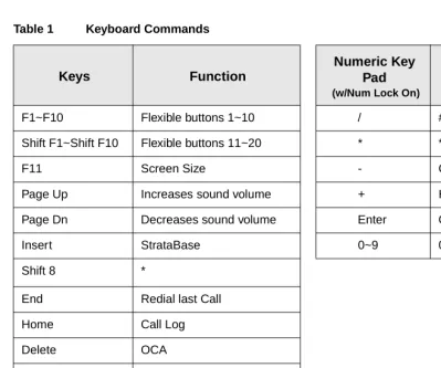
Table 1 Keyboard Commands
Keys Function
Numeric Key Pad
(w/Num Lock On)
Function
F1~F10 Flexible buttons 1~10 / #
Shift F1~Shift F10 Flexible buttons 11~20 * *
F11 Screen Size - Cnf/Trn
Page Up Increases sound volume + Hold
Page Dn Decreases sound volume Enter On/Off Hook
Insert StrataBase 0~9 0~9
Shift 8 *
End Redial last Call
Home Call Log
Delete OCA
Enter On/Off Hook
Installation
9
Installation
2
This chapter shows you how to install the PC-DKT card and software. Installation will be simple if you read this entire chapter first, then carefully follow all of the steps.
Step 1: Before You Start
Make Sure You Have Everything
The PC-DKT pack includes:
♦ PC-DKT card
♦ PC-DKT software
♦ Keyboard template
♦ 6-ft. line cord (RJ-11 connector)
♦ 6-ft. line cord for analog port (RJ-45 to RJ-11)
♦ This user guide
Optional equipment available from Toshiba:
♦ Handset/Cradle with phone cable
Step 1: Before You Start ————————————————————————————————————
Make Sure Your PC Meets PC-DKT’s Minimum Requirements
♦ 486 DX2-66 MHz processor
♦ Windows 95 or Windows 3.1/3.11
♦ 8MB of RAM
♦ 3.5” 1.44MB floppy-disk drive
♦ 5MB of free hard disk space
♦ 1 free ISA slot (8 or 16-bit)
♦ VGA color monitor
♦ Sound card and speakers (optional)
Note The sound card should be Sound Blaster™ equivalent.
Do You Know How to Work on PCs?
You should have a basic understanding of the installation of internal PC hardware devices, interrupts and addresses. If you are unsure, contact a qualified installation specialist.
CAUTION! Toshiba cannot be held liable for any damage that is caused during
the installation of the PC-DKT card.
Read This Important PC-DKT Handling Information
The PC-DKT card is delicate. Handle it with care! Always:
♦ Check that the PC case is correctly grounded.
♦ First, touch metal (e.g., your PC casing) before touching the PC-DKT card. This
ensures that there are no static charges.
♦ When not in use, always keep the PC-DKT card in the anti-static bag. Never place it on a table or other areas where it is susceptible to static charge.
♦ Ensure that the PC-DKT card is removed from the static-free bag in a clean,
dust-free environment.
————————————————————————————————— Step 2: Install the PC-DKT Card
Installation
11
Step 2: Install the PC-DKT Card
Important! You must install the PC-DKT card before installing the PC-DKT
software.
Since this is not a “plug-and-play” device, you must configure the PC-DKT card’s IRQ and Memory Address settings. In order to configure the card’s settings, you must first find out what settings are available on your PC.
➤
To install the PC-DKT card1. Check for available IRQ and memory address settings on your PC. The factory default is IRQ 5 and Address 380h. If these are not available, choose an available IRQ and Address (see valid Interrupts and Addresses in Table 2).
Windows 95: from the Taskbar, click Start, Settings, then Control Panel. Double-click the System icon. Click the Device Manager tab and make sure “Computer” is highlighted. Click Properties button. By clicking on “Interrupt request (IRQ)” and “Input/output (I/O),” you can view the settings for the system.
Windows 3.11: exit the DOS C:\ prompt and run Microsoft Diagnostics (type
MSD.EXE).
2. Exit all open applications.
Windows 95: From the Taskbar, click Start, then Shut Down. You are asked to confirm the shutdown.
Windows 3.1/3.11: From the Program Manager’s windows, click File, then Exit Windows to go to the DOS prompt.
3. Power off the PC and disconnect all cables.
CAUTION! Make sure you are properly grounded with a grounding strap before
opening the computer.
WARNING! Avoid electrical shock! Make sure the power is off before moving
Step 2: Install the PC-DKT Card—————————————————————————————————
4. Unscrew and remove the PC’s cover.
5. Unscrew and remove the metal bracket adjacent to an empty ISA expansion slot (shown at right).
6. Check PC-DKT’s IRQ interrupt and address settings (shown at right). The PC-DKT must not conflict with another device’s interrupt or memory address settings. If a conflict exists, change the jumpers with the aid of Table 2.
2138
2178
Strata Phone System
Power Fail Phone
Fax/ Modem
Multi-Media
Handset/ Headset
Address Select
9 8 7 6 5 4 3 2 3 5 7 9 10111215 IRQ Select
Address Select
9 8 7 6 5 4 3 2 3 5 7 9 10111215
IRQ Select
————————————————————————————————— Step 2: Install the PC-DKT Card
Installation
13
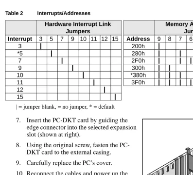
7. Insert the PC-DKT card by guiding the edge connector into the selected expansion slot (shown at right).
8. Using the original screw, fasten the PC-DKT card to the external casing.
9. Carefully replace the PC’s cover.
10. Reconnect the cables and power up the PC.
Important! When powering up the PC, watch for any errors that may come up. If any
errors associated with the PC-DKT card appear, you may have an Interrupt or Address conflict. If this happens, you must pick a different setting.
Table 2 Interrupts/Addresses
Hardware Interrupt Link Jumpers
Memory Address Link Jumpers
Interrupt 3 5 7 9 10 11 12 15 Address 9 8 7 6 5 4 3 2
3 | 200h |
*5 | 280h | |
7 | 2F0h | | | | |
9 | 300h | |
10 | *380h | | |
11 | 3F0h | | | | | |
12 |
15 |
| = jumper blank, = no jumper, * = default
Step 3: Connect the Cables ———————————————————————————————————
Step 3: Connect the Cables
1. Connect a 6-wire phone cable (supplied) between the Strata DK and PC-DKT’s Port 1.
2. (Optional) Connect a 6-wire phone cable between a Digital Key Telephone and the PC-DKT’s Port 2. This backup phone operates normally when the PC-DKT application is closed down or your PC is turned off.
Note If you do not connect a backup telephone, make sure you enter an extension in the Forward on Exit box (see Page 17).
3. Connect a 4-wire/8-wire phone cable (supplied) between your fax/modem and PC-DKT’s Port 3.
4. (Optional) Connect the special 4-wire/mini-plug cable (supplied) between your PC sound card and PC-DKT’s Port 4. Make sure to match the IN mini-plug to the IN jack on the sound card, and the OUT mini-plug to the OUT jack on the sound card.
5. (Optional but highly recommended) Connect a cable between a handset/cradle (option available) and the PC-DKT’s Port 5.
Note A headset may be used but it lacks the functionality of the cradle hookswitch. If you use a 405Flex-MPS II headset, use the following settings: Transmit Wheel = 7 or 8, Slide Switch = E.
CAUTION! Before connecting any cables in this step, make sure that you
are connecting the proper cable to the port. If you connect the wrong cable, damage to the PC-DKT card, the PC and/or the auxiliary equipment (e.g., modem, fax, etc.) can result.
——————————————————————————————————— Step 4: Install the Software
Installation
15
Step 4: Install the Software
Before installing the software, make sure there is a minimum of 5MB of free disk space. This space is required for running the Call Log and StrataBase functions. You should also know the IRQ and Address settings for the PC-DKT.
➤
To install the PC-DKT software1. Insert the installation disk into your floppy-disk drive (A: or B:).
Windows 95: Click Start followed by Run.
Windows 3.1/3.11: From the Program Manager, click File.
2. Type A:\SETUP.EXE and press Enter.
3. When the Interrupt Request Setting Options dialog box displays (shown at right), select the appropriate IRQ. This setting must match the setting on the PC-DKT card. Click Continue.
4. When the Address Settings Options dialog box appears (shown at right), select the appropriate Address. This setting must match the setting on the card. Click Continue.
Once installation is complete, click Restart Windows so that the PC-DKT’s device driver can properly initialize.
21
42
21
Step 5: Set System Parameters —————————————————————————————————
Important! Always use the dialog box provided to restart Windows and never the
“Ctrl-Alt-Del” method.
5. (Optional) If you have Windows 95, make a Shortcut icon for the PC-DKT on the Windows desktop.
6. (Optional) Place the keyboard template (included) on your keyboard.
Step 5: Set System Parameters
1. Windows 95: Double-click the PC-DKT icon or click Start, then Programs, Toshiba PC-DKT, and PC-DKT.
Windows 3.1/3.11: Find the Toshiba PC-DKT group and click the PC-DKT icon.
2. From the menu bar, click Setup, then System Setup.
3. From the System Setup dialog box (shown right), modify:
♦ System – choose the type of Strata
DK system you are using. Features may vary, see your System
Administrator for details.
♦ Sound source – set the PC-DKT’s
ring tone by selecting one of the following:
Sound card – define your own system tones using the Ring Sounds option on the Setup Menu (see ‘Ring sounds’ on Page 48).
On-board buzzer – emits single beep when receiving an incoming call.
PC Speaker – provides the tones and is the default device for the PC-DKT.
Multimedia (Port 4 on the PC-DKT card) – provides voice announcements and true DKT ringing tones.
————————————————————————————————— Step 5: Set System Parameters
Installation
17
If you choose Multimedia, you must connect the multi-media cable (supplied in the pack) to the line-in, line-out connection on the sound card.
♦ Alpha tagged Central Office lines… – these (CO) lines have been given a name
in system programming for identification purposes. You can add, edit, or delete up to 200 CO lines (see your System Administrator for details).
♦ Miscellaneous – Dial 9 (default to access an outside line) - change as required;
make the PC-DKT a 10 or 20-button phone; check the Handset Cradle Present box if using a cradle; pop VM access panel on MSG; and set the number of calls you wish to log (default is 100).
♦ Forward on exit – enables you to forward all your incoming calls to the extension
of your choice (default is No Forward on exit).
Note This feature must be activated if there is no backup telephone.
4. When you are satisfied with your settings, click OK.
Button Setup
Before using the PC-DKT you must program the buttons that emulate the flexible buttons on a 20-button DKT. These buttons may be either line or feature buttons, depending on your system programming. The flexible buttons are programmed within the telephone system, therefore, you must define the buttons to the PC-DKT.
1. Click Setup, then Button Setup. A dialog box displays (shown at right).
2. Under Flexible Key, highlight a line button from the list; change its Key Type to one of the following:
♦ [PDN] Key (up to four [PDNs] can be selected)
♦ External Key (CO line button or
Pooled Line Group button)
♦ Speed Dial Select (SDS) button
♦ None of the Above (non-line buttons; e.g., [SDNs], [PhDNs], DSS, Call
Step 6: Set Up StrataBase ———————————————————————————————————
3. Enter a custom name in the Text on key box.
4. Continue the process until all buttons have been set up.
5. Click OK.
Customize the PC-DKT (optional)
Various features are available from the Setup Menu to customize the PC-DKT. They are:
♦ Pop Up Options – set amount of time the Caller ID box will display or stop it
from displaying at all.
♦ Extension Name – customize the LCD with your name, and/or extension number.
♦ LED Colors – set the LED colors for lines which are busy, idle, in use, etc.
♦ Ring sounds – customize the ringing tones for incoming calls.
♦ Paging Group Names – customize the list of group names (eight internal and
four external) for paging.
♦ Voice Mail Settings – connect the PC-DKT to your voice mail application and
customize the button labels.
Configure these features to suit your needs. See ‘Setup Menu’ on Page 45 for details.
Step 6: Set Up StrataBase
The StrataBase functions as a dialing directory of external telephone and internal extension numbers. From a StrataBase record, you can dial any number displayed on the screen.
➤ Create a database of frequently-called people/companies. You can include an extension number, and outside, mobile, and alternate telephone numbers for each person listed. (See ‘StrataBase’ on Page 25 for instructions on adding and using the StrataBase.)
————————————————————————————————— Step 7: Program the Strata DK
Installation
19
Step 7: Program the Strata DK
For the PC-DKT to perform properly, some Strata DK telephone system settings are necessary. Check with your System Administrator.
Note Refer to the Strata DK Installation and Maintenance and Strata DK
Programming Manuals for additional information on these programs.
Program Settings/Comments
10-1
System Assignments
LED 17 ON
Reduces station-to-station talk path volume (-8 dB).
31
Station Class of Service
LED 01 ON
Disables the internal call Handsfree Answer Back function.
The PC-DKT does not require additional programming to activate TAPI, except if ANI, DNIS, and/or Caller ID are to be sent from the PC-DKT to a TAPI compliant application. To activate this feature, the following program changes are required:
03
Flexible PCB Slot Assignments
PDKU2 (OCA, DIU) 62 PDKU2 (DSS, OCA, DIU) 64
Assigns the appropriate PDKU2 cards as having the DIU interface.
20
Computer and Data Interface Unit Configuration
LED 11 RPCI-DI DNIS to PC Option
DNIS Number or Name tag information that is sent to a telephone can be sent, or blocked. If DNIS information should be sent from the PC-DKT to the TAPI application, turn LED 11 ON; if this information should not be sent, turn LED 11 OFF.
LED 10 RPCI-DI Caller ID and ANI to PC Option
If Caller ID and ANI information should be sent from the PC-DKT to the PC to which it is connected, turn LED 10 ON; if this information should not be sent to the PC, turn LED 10 OFF.
Operation
21
Operation
3
This chapter contains instructions for using the PC-DKT and its menu features. The features are divided into four categories: File, Functions, Setup and Help. Options are described in order of their appearance on the menus.
Basic Operation
Accessing the PC-DKT
Windows 95: Double-click
...or click Start, then Programs, Toshiba DKT and PC-DKT.
Windows 3.1/3.11 From the Toshiba PC-DKT group, click PC-DKT.
The PC-DKT Main screen displays. If you have a backup phone connected, it shuts off until you exit the PC-DKT.
Exiting the PC-DKT
1. Click the Windows Close button
...or click File, then Exit.
Basic Operation—————————————————————————————————————————
Note If you do not have a backup phone, be sure to enter an extension number to which your calls can be forwarded (see Forward on exit on Page 17 for instructions).
Quick Reference
The PC-DKT provides several ways to access its functions — menu buttons, menu options, keyboard command keys and keyboard shortcuts. For example, to access the StrataBase, you can click on the StrataBase button, select StrataBase from the File menu, or press Insert or Alt+F, Alt+S on the keyboard. The following table gives you brief instructions on accessing and using PC-DKT’s basic functions.
Function Action
Dial Numbers Use your keyboard’s numeric key pad or the main
screen’s dial pad keys.
Answer a Call Click On Hook or lift the handset. (See also ‘Caller
ID” on Page 23.)
Make a Call Click a [DN] for an internal call or a line button for an
external call. Dial the number or use StrataBase.
Transfer a Call Click Cnf/Trn, – (minus) on numeric keypad, or access
Transfer on the Functions menu. Dial the directory number where the call will be transferred. (See ‘Trans-fer’ on Page 41 for more details.)
Redial a Call Using the same [DN] or line button that you used to
make the call the first time, press End or click Redial.
Conference a Call While on a call, click Cnf/Trn or press – (minus) on
numeric keypad. Dial a [DN] or access a second CO line and dial the telephone number. When the party answers, click Cnf/Trn again. (See ‘Conference Call’ on Page 24 for details.)
————————————————————————————————————————— Basic Operation
Operation
23
Caller ID
The PC-DKT receives and displays the Caller ID Received dialog box during an incoming call (sample shown at right).
The PC-DKT searches the
StrataBase for a telephone number and displays the corresponding name of the caller. If the number is not found, the unlisted number appears with the statement “Not in Directory.”
Using the Pop up options feature on the Setup Menu, you can set the length of time the Caller ID box is displayed or disable the function (see ‘Pop up options’ on Page 45).
Message Waiting Click Msg and enter your security code. (See
‘Mes-sage Waiting’ on Page 39 for more details.)
Access Voice Mail Click File, then Voice Mail Access Panel. (See ‘Voice
Mail Access Panel’ on Page 31 for more details.)
Change Main Screen Size
Press F11 or click <<, >>.
Change Sound Volume
Press Page Up/Page Down or use Volume Control on the Main screen.
Access StrataBase Press Insert, click on StrataBase or access
File/Strata-Base. (See ‘StrataBase’ on Page 25 for more details.)
View Call Log Press Home, click Call Log or access File/View Call
Log. (See ‘View Call Log’ on Page 28 for more details.)
Function Action
2181 Main
Screen
Copy Add/Show
Basic Operation—————————————————————————————————————————
On Hook/Off Hook Button
Functions the same way as the On Hook/Off Hook button on the Main screen. When you click this button, the Caller ID dialog box is closed and no longer displayed.
Main Screen Button
If the PC-DKT Main screen is buried under other application windows, click the Main screen button to view it.
Add/Show Button
The Add/Show button is context sensitive. It displays as Add if the incoming caller does not appear in the StrataBase or Show if the caller is already in the StrataBase.
Click the Show button and the StrataBase record for the incoming caller displays. Click the Add button and the Add/Edit Telephone Details dialog box displays. You can now add the caller to your StrataBase.
Copy Button
The Caller ID information is placed on the Clipboard and exports into compliant Windows applications. You can select the copied fields through the Clipboard options panel of the Pop up options dialog box.
Conference Call
The PC-DKT enables you to add other parties to an existing party line. The following conferencing configurations are possible:
♦ up to two stations and two CO lines
♦ up to three stations and one CO line
♦ up to four stations
➤
To make a conference call———————————————————————————————————————————— File Menu
Operation
25
Notes
● If you receive a busy tone or no answer, click Cnf/Trn to return to the original
connection.
● The new station is not conferenced unless its user lifts the handset or selects a
[DN] to answer.
File Menu
This section shows you how to use the features in the File drop-down menu.
➤ From the menu bar, click File.
StrataBase
StrataBase functions as a dialing directory and provides names, addresses and telephone numbers that can be used by the PC-DKT in the Caller ID and Call Logging functions. Each entry in the StrataBase is a separate record with clearly defined fields.
2. Dial a [DN] or access a second CO line and dial the telephone number.
3. When the party answers, click Cnf/Trn.
Wait for the called station to answer. The [DN] or CO line LED from which the confer-ence originated flashes at the in-use rate and all parties are connected.
4. Repeat the procedure to add other CO lines or [DNs], remembering not to exceed the allowed number.
File Menu————————————————————————————————————————————
Accessing StrataBase
➤ Click File, then StrataBase
...or click the StrataBase button
...or press Insert
...or access it from a Called ID pop-up box.
Note When you first install the PC-DKT there are no names in the directory.
Using StrataBase as a Dialing Directory
➤ With the person/company’s record displayed, click on the extension/telephone number you want to dial. The call is initiated and the Main screen is displayed with the number you dialed shown in the LCD.
———————————————————————————————————————————— File Menu
Operation
27
Adding a StrataBase Record
1. From the StrataBase dialog box, click Add
...or when you receive a call, click Add from the Caller ID Receive dialog box.
The Add/Edit Telephone Details screen displays (sample shown at right).
2. Mouse or tab through the fields (field lengths noted in parenthesis on sample screen); type in the entries. The only required entry is the person’s last name.
Telephone numbers can include dashes. If you use ( ) around area codes, they must be preceded by a 1 (e.g., 1(800)...).
If your application requires an Account Code (called Forced) precede the telephone number, click Auto dial first: field. The Account Code automatically dials first, when you call the individual/company’s external number. Voluntary Account Codes are optional and can be added after accessing a CO line or during a call. They cannot be added after the call is disconnected.
3. When you are finished, click OK to save the entries, or Cancel to escape the screen without saving. You can also dial a displayed telephone number from this screen.
Editing a StrataBase Record
1. With the person/company record displayed on the StrataBase screen, click Edit.
2. Make the changes required (see ‘Adding a StrataBase Record’ on Page 27).
3. Click OK when finished.
File Menu————————————————————————————————————————————
Deleting a StrataBase Record
1. With the person/company record displayed on the StrataBase screen, click Delete.
2. Click Yes to confirm the deletion and the record is erased from the database. Deleted records cannot be recovered.
Searching StrataBase
With entries in your directory, you can begin to search through them.
1. From the StrataBase screen, select a search field from the Search for... drop-down menu. Choose: Last Name, First Name, Company, Address, Internal Nos or External Nos.
2. Type the first few letters/numbers of the entry for which you are searching. If your selection is in the list of entries, it appears in the Found... list. If you enter only one letter, StrataBase searches for all names containing that letter (see sample at right).
View Call Log
The PC-DKT logs all your incoming and outgoing calls. You can view calls by Details (names, telephone numbers), Call Direction, Call Type and Incoming Call type.
The dialog box contains a list of all specified calls with the last call at the top of the list. Any number in the list can be dialed, so that the log also acts as a dial-out directory. You can scroll up and down the list by using the arrow buttons or select an entry by the mouse.
The Call Log also includes:
♦ Mouse or keyboard access to ring any number.
♦ Search field enables listing of particular numbers/names.
♦ Option to delete one entry, a block of entries or the whole Call Log.
Remember: The Call Log accumulates data on every call you receive and
continuously adds entries. Therefore you need to check that your default setting for
———————————————————————————————————————————— File Menu
Operation
29
deleted entries is set at a reasonable number (e.g., 100). To check or change the setting, use System Setup in the Setup menu.
➤
To access View Call Log➤ Click File, then View Call Log
...or click the Call Log button from the Main screen
...or press Home.
Details
Click on Show Names to show the names associated with the numbers found in the StrataBase. Numbers that cannot be found will show Unlisted. Click on Show Numbers to show manually dialed calls not in StrataBase.
Call Direction
➤ Click on Incoming, Outgoing, or Show Both to display the needed data.
Call Type
➤ Click on Internal, External, or Show Both to display the needed call types.
Incoming Calls
The Incoming Call Log dialog box is activated only when you select the Incoming Calls or Show Both options under Call Direction.
File Menu————————————————————————————————————————————
Wipe Log
If you select this button all your entries (i.e., incoming, outgoing) in the Call Log are deleted, regardless of what is displayed on the screen. For safety reasons, a
Confirmation dialog displays, asking you for confirmation of the deletion.
Delete
Single entries can be deleted from the log by highlighting them with the mouse or arrow keys and then pressing Delete or clicking Delete.
➤
To delete multiple entries➤ Click the left mouse button but do not release and run the mouse cursor down the list. This highlights a block of entries.
...or click on one entry. Then hold Shift and click another entry. This highlights all entries in between.
...or hold down Ctrl and click on each individual entry with the mouse cursor. Each entry will be highlighted.
Pressing Delete in each case deletes all of the highlighted entries.
StrataBase
This function enables you to go directly to StrataBase to add/edit/delete information.
➤ Select any entry in the list by clicking on it with the mouse or using Tab. Click StrataBase. If the selected entry pertains to an individual already in the
StrataBase, the StrataBase screen is displayed with the applicable information. If not, the Add/Edit Telephone Details screen is displayed.
CALL
This function enables the Call Log to be used both as a redial and dial-out directory.
———————————————————————————————————————————— File Menu
Operation
31
Voice Mail Access Panel
To access your Voice Mail System, you must ensure that it is connected correctly (see ‘Voice Mail Settings’ on Page 49). Using the Voice Mail Settings feature, you can change the six features you can access, the button labels, and add keyboard shortcuts. The following procedure uses PC-DKT system defaults but can be varied for your own feature settings.
You must select the “Pop VM Access Panel on MSG press” option on the System Setup screen for the Msg button to work in this feature (see ‘Step 5: Set System Parameters’ on Page 16 for instructions).
➤
To display the Voice Mail Access panel1. Click File, then Voice Mail Access Panel
...or click Msg.
The Log-In String dials. Once you have logged in to the VM system, the Voice Mail Access Panel dialog box displays.
2. Click the Play, Next, Last, Rewind or Stop buttons to listen to your messages.
The access buttons use the options set in the Voice Mail Setup dialog box. Note that each button can be operated in the standard Win-dows Alt-(underlined) Key manner, as long as the keys were configured earlier.
3. (Optional) Click Delete to delete a message.
Functions Menu—————————————————————————————————————————
Functions Menu
This section shows you how to use the features in the Functions drop-down menu (shown right).
➤ From the menu bar, click Functions.
Page All
Enables you to make page announcements to all stations and external speakers.
➤
To make an All Call Page1. Click Functions, then Page All. The LCD displays “All Call Paging”.
2. Make your announcement in a normal voice and hang up.
Automatic Callback (ACB)
If you reach a busy, DND station or line group, you can set ACB to have the system call you back when the called station/line group becomes available.
➤
To set ACB1. After reaching a busy station/line group, click Functions, then Automatic Callback.
2. Hang up the telephone. Your station rings quickly when the called station or line group becomes idle.
3. Answer within three rings to prevent the callback from being canceled. 4. When you are finished, click
Hang Up.
The Voice Mail Terminated dialog box dis-plays asking you to confirm termination of the session.
5. Click OK. The Main screen is displayed.
————————————————————————————————————————— Functions Menu
Operation
33
➤
To cancel ACB➤ Click Functions, then Automatic Callback.
Call Forward
You can set your telephone [DN] with a variety of Call Forward modes. If you set Call Forward:
♦ CO lines that ring your station only will forward. CO lines that ring more than one
station will not forward.
♦ CO line calls transferred to your station will forward.
♦ Internal calls will forward (Handsfree and Off-hook Call Announce (OCA) calls optionally may or may not). CF-External will not forward on internal calls.
♦ Call Forward has priority over the Station Hunt feature.
♦ Call Forward must be set before the call is received.
Stations can have many [DNs]. However, a station must be the designated owner of a [DN] to Call Forward the [DN]. Each station is designated as the owner of at least one [DN] which is called the station's [PDN].
Call Forward buttons are used to Call Forward the [PDNs] only. Use the Call Forward access codes to Call Forward [PhDNs].
➤
To set/cancel Call Forwarding to an internal number1. Click Functions, then Call Forward.
2. Select one of the following:
All Calls Forwards all calls regardless of the condition of your line.
Functions Menu—————————————————————————————————————————
➤
To set/cancel Call Forward to an external number➤ Click Functions, then Call Forward, External (On/Off). The LCD shows CF-EXT and the calls are forwarded to an external location (determined by system
programming). To cancel the forward, re-select External (On/Off) to toggle the feature off.
No Answer Forwards all calls to your station if you do not answer within a designated time. Your station can be programmed not to Call Forward-No Answer when receiving Voice First (hands-free) or OCA calls.
Callers can activate Call Forward-No Answer by dialing 1 during their voice announcement.
Busy/No Answer Forwards all calls to your station when your line is busy, in Do Not Disturb mode or if you do not answer within a designated time.
Your system can be programmed to bypass Call Forward-No Answer by dialing 1 during their voice announcement.
Cancel Cancels all call forwarding. No further action is required.
3. Enter the extension number where your calls will be forwarded. Click OK.
4. If you selected No Answer or Busy/No Answer, enter the time delay (08~60 seconds). Click OK.
————————————————————————————————————————— Functions Menu
Operation
35
Display
➤ Click one of two selections: Port Number Display (the port number that your extension is connected to), Station Number Display (your extension number). The number displays in the LCD for approximately two seconds.
Call Pickup
You can pick up a call that is ringing at another station, a call placed on hold at another station and other types of calls.
Directed Call Pickup (i.e., Specific Extension, CO Line On Hold) provides you with several ways to pick up incoming calls, calls on hold at other stations, telephone group page and an external page.
➤
To pick up a call1. Lift your handset.
2. Click Functions, then Call Pickup.
3. Select one of the following:
Specific Extension – You are prompted to enter the ringing or held extension number.
CO Line On Hold – You are prompted to enter the held CO line number.
Any Ringing Line – You are connected to any ringing CO line (usually used with a night bell). No further action is required.
Functions Menu—————————————————————————————————————————
Door Phone Access
Door phones can be used to call digital and electronic telephones selected in system programming. You can call a door phone and monitor the area surrounding the door phone.
➤
To call/monitor a door phone1. Click Functions, then Door Phone Access. A dialog box appears.
2. Enter the door phone number (1~12). You can now call/monitor the door phone.
➤
To answer a door phone➤ When you hear the distinctive ringing tone, lift the handset.
Use CO Line
When you receive a call on a CO Line or [DN], the associated LED flashes.
➤
To use a specific/group CO Line to make a call1. Click Functions, then Use CO Line.
2. Select one of the following:
Specific – A dialog box displays. Enter CO line number (1~200) and click OK.
Group – A dialog box displays. Enter a Group line number (1~16) and click OK.
3. The PC-DKT goes off-hook. The LCD of the Main screen shows “Using Line X, Dial Tel Number”.
Notes
● If your station is programmed with Ringing Line Preference, you can answer the
longest ringing line by lifting the handset.
● The optional handset/cradle is supplied with a built-in hookswitch. Lifting the
————————————————————————————————————————— Functions Menu
Operation
37
Page Group
To customize the group names used in this option, see ‘Paging Group Names’ on Page 49 for instructions.
➤
To make a page announcement1. Click Functions, then Page Group.
2. Select one of the following:
Internal Zone – A list of up to eight internal paging groups displays.
External Zone – A list of up to four external paging groups displays.
3. Select a paging group from the list.
4. Using a normal voice, make your announcement and hang up.
Pick Up Group
You can pickup calls ringing stations within your own group, in another group or from the page zones.
➤
To pickup a call1. Click Functions, then Pickup Group.
2. Select one of the following:
Own – You are connected to the caller.
Selected – You are prompted for a group number.
External Page – You are connected to the caller.
Functions Menu—————————————————————————————————————————
Call Parking
The Call Park feature enables you to hold a call temporarily in an orbit. Anyone can then retrieve the call from orbit using the same or a different station. There are 20 General Park Orbits for the system and one Personal Park Orbit for each station.
Once you have parked a call in orbit, you can:
♦ Hang up and retrieve the parked call at a later time
♦ Originate another call
♦ Access a voice paging device to announce the parked call for pickup from another
station
If you park a call and your station is idle when the system Call Park Recall timer expires, the parked call automatically recalls to your station. If your station is busy, the parked call camps-on to your station.
➤
To park a call1. Click Functions, then Call Parking.
2. Select Park Call.
3. Enter Orbit number 999 and click OK. The Strata DK system automatically selects the lowest available orbit number and displays it on your LCD. If you are using a Personal Park Orbit, instead of the Orbit number, enter the extension number where you want to park the call.
4. The LCD on the Main screen displays “LNXXX ORBIT YYYY”.
➤
To retrieve a call1. Click Functions, then Call Parking.
2. Select Park Call.
3. Enter the Orbit number (900~919) or the extension number (if Personal Park Orbit) where the call is parked.
————————————————————————————————————————— Functions Menu
Operation
39
Message Waiting
If you call a busy station [DN] or if no one answers, you can leave a message waiting indication. The user can call you back by pushing the Msg button. (Voice mail devices can also leave message waiting indications).
Note You can set the Msg button to activate the Voice Mail Access dialog box, by using the “Pop VM Access Panel on MSG press” on the System Setup screen (see ‘Step 5: Set System Parameters’ on Page 16 for instructions).
➤
To set/cancel Message Waiting Light at another station1. Click your [DN] and dial a [PDN] or [PhDN]. You hear ringback or busy tone.
2. Click Functions, then Message Waiting.
3. Click Set at Remote Station. The Message Waiting light is set at the distant station.
Answer Message Waiting
Your station rings the caller or voice mail device that left the message. If there is no answer, hang up and try later.
➤
To answer Message Waiting1. Click Functions, then Message Waiting.
2. Click Answer. This calls the station which set the message. The Message Waiting light turns off when the caller answers the phone.
...or when the Msg LED is flashing, lift the handset and click Msg.
Note If the Msg LED continues to flash, you have more than one message.
3. After receiving the message(s), place the handset on hook.
Cancel Message Waiting Light
Functions Menu—————————————————————————————————————————
➤
To cancel Message Waiting Light at your station1. Click Functions, then Message Waiting.
2. Click Indication Cancel. The Message Waiting light turns off.
Override
There are three override options:
♦ Busy Override enables you to send a muted ring tone to a busy station to indicate
that a call is waiting.
♦ Do Not Disturb Override lets you send a tone to an idle or busy station in the Do Not Disturb mode to indicate that a call is coming in.
♦ Executive Override lets you enter an established conversation.
Note Your station must be enabled in system programming to use the Do Not Disturb and Executive Overrides. Also, a telephone can be enabled in system programming to block Executive Override from all other telephones.
➤
To send an override signal/enter into a conversation1. Click Functions, then Override.
2. Select one of the following:
Busy Override – the call is now provided with Busy Override.
DND Override – the call is now provided with Do Not Disturb Override.
Executive Override – you can now enter into the conversation.
————————————————————————————————————————— Functions Menu
Operation
41
Transfer
This function enables you to transfer your calls to an idle or busy station. You can answer a call that is transferred to your station, whether your phone is idle or busy by first putting the active call on hold.
Note You cannot transfer (or camp-on) to stations that are in the DND mode.
➤
To transfer a call1. Click Cnf/Trn
...or click Functions, then Transfer
...or press - (minus) on the numeric keypad
2. Dial the directory number to where the call will be transferred.
3. Announce the call if the called station is idle, then hang up. The call transfers.
Note The directory number could be the [DN] of a telephone, a Hunt Group Number or an ACD Group.
➤
To answer a transferred callWhen receiving a transferred call, you hear an internal ring tone and the [DN] or Line LED flashes.
Functions Menu—————————————————————————————————————————
LCD Messaging
Displays an LCD message to callers while you are away from your station. You can also send a message to another station.
➤
To set/clear an LCD message1. Click Functions, then LCD Messaging.
2. Select one of the following options:
Out to Lunch In a Meeting
No further actions are needed.
Call... Back at... Return on...
A data request box displays with the first word(s) displayed (e.g., Call). Complete the message and click OK.
System Message A dialog box displays prompting you to enter a system message number (65~99). Enter the number and click OK.
Note The Strata DK system installer must enter these messages for the system.
————————————————————————————————————————— Functions Menu
Operation
43
➤
To send an LCD messagePersonal Message
Note Depending upon the Strata system you are using, this option may not be available to you. Check with your System Administrator.
A dialog box displays. You can create up to 10 personal messages (default titles are Unknown Message #10~#19). Use the drop-down menu to select a message and type or edit a personal message. Click OK.
Clear Msg Clears current message.
1. Click Functions, then LCD Messaging.
The LCD Messaging box displays.
2. Click Send Message. A dialog box displays asking you to enter the extension of the phone to which you are send-ing the message.
3. Enter the extension number. Click OK.
A second dialog box displays.
4. Select the type of message to be sent (i.e., personal, system).
If you chose personal, a list of personal mes-sages is displayed. Select a message.
If you chose system, enter a system message number (65~99).
5. Click OK. The message is sent and the Message Waiting Light on the receiving phone is lit.
Your LCD displays “Sent xxxM” (xxx = desti-nation extension number) until the message is picked up. The receiving phone displays “Call xxx-xxxM.”
Functions Menu—————————————————————————————————————————
Timed Reminder
You can set five separate reminders at your station. Your station will sound a distinct beeping at the exact minute and hour you set for any of these reminders, either once or daily.
➤
To enter a Timed Reminder1. Click Functions, then Timed Reminder.
2. From the Select reminder drop-down menu, select a reminder number (1~5).
3. Set the time by entering two digits for the hour of the day (HH), then two digits for the minutes (MM).
4. If you require the message to
appear on a daily basis, click Daily reminder.
5. From the Message drop-down menu, click a personal or system message to display on the Timed Reminder. Also available is a <No Message> display.
6. Click Set.
➤
To cancel a Timed Reminder1. Click Functions, then Timed Reminder.
2. From the Select reminder drop-down menu, select a number (1~5).
3. Click Clear.
Record
➤
To activate the recording feature1. Click Functions, then Record.
2. Activate your sound recorder software.
3. Follow the required steps in your sound recorder software application.
—————————————————————————————————————————— Setup Menu
Operation
45
Setup Menu
Always on top
➤ Click Setup, then Always on top to display the PC-DKT on top of all active applications (enabling you to see it at all times). Click Always on top again to disable the feature. The Main screen displays as a normal window behind the active application.
Button Setup
The Button Setup enables you to set the Flexible buttons to the following key types:
♦ [PDN] Key
♦ External Key
♦ Speed Dial Key
♦ None of the above
♦ [SDN]/[PhDN]
See ‘Button Setup’ on Page 17 for instructions on using this function.
Pop up options
The Pop up options dialog box contains two panels: Pop up box and Copy button.
Pop up box Panel
The four options within this panel determine the way that the PC-DKT reacts when you receive an incoming call.
2148
Setup Menu ——————————————————————————————————————————
The first three define the length of time the Caller ID box is displayed while the fourth option lets you enable or disable the Caller ID function.
If you want the Main screen to display whenever the PC-DKT goes off-hook, click “Going off hook pops main window” in the lower left hand corner of the dialog box.
Copy button Panel
Determines the type of information that is passed to the clipboard when you receive an incoming call and provides a means of passing a Caller's ID to TAPI.
Note The Name/Number option must be ordered from your telephone company at an additional cost.
Extension Name
1. Click Setup, then Extension Name.
2. Click Set and enter a name and extension number. The name/number can be displayed in the LCD of the Main screen when PC-DKT is in idle state. It is also seen on the called party’s display.
—————————————————————————————————————————— Setup Menu
Operation
47
LED Colors
This feature enables you to define line button colors in each of their states.
➤
To configure the LED Colors option1. Click Setup, then LED Colors.
2. Select an LED Status by clicking on the corresponding radio button.
The LED Colors dialog box is displayed.
3. Select a box from the Color States panel, then a color from the grid on the left.
4. Select the second box from the Color States panel, then a color from the grid on the left.
If you choose the same color for this box that you did in Step 3, the LED does not flash and is a steady color. If you choose a different color, the LED flashes. For example, if the first box is red and the second is blue and the line state is On Hold, then, whenever a call is put on hold the line button flashes red and blue.
5. Click OK. The PC-DKT automatically updates LEDs to the selected colors.
Setup Menu ——————————————————————————————————————————
Ring sounds
If you have a sound card, you can select the way ringing tone is applied when receiving a call on a [DN] or CO line.
➤
To set ringing tone1. Click Setup, then Ring Sounds.
2. From the dialog box, select Intercom/ Line and the default ringint.wav for the intercom line or ringext.wav for the CO lines displays in the Associated Sound... box. This is the sound file that is played whenever you receive an incoming call on that Intercom/Line.
3. To change the sound file, click Browse and find the WAV file you want to use. Select the file and click OK. The file name displays in the Associated Sound... box.
4. (Optional) Once the file is listed in the box, you can hear the ringing tones by clicking Play.
5. Repeat the procedure for each line for which you want to set/change a ringing tone.
6. To change the Recall WAV file, highlight the default selection of recall.wav and click Browse. Repeat the selection process in Step 3.
7. (Optional) Click “Emergency WAV file” to activate the option. If you want a shorter/longer ringing time, change the five second default. To change the default WAV file, highlight the default selection of emg.wav and click Browse. Repeat the selection process in Step 3.
8. When you are finished, click OK.