Development of Methodology for Evaluation Thermal Performance of Earth
Berming System for Building Envelope
Mr.Prafull P.Tayshete, Prof..N.N.Shinde* ,
1
Department of Energy Technology, Shivaji University Kolhapur
Abstract- Earth berming is a storage device and helps space conditioning inside building envelope, if used carefully and tactfully. The thermal analysis of wall plus earth filling outside become composite structure and can be used for maintaining IEQ.
The thermal analysis of earth berming composite wall become complex if it is added with passive land scapes. This work is associated with development of methodology for evaluation of thermal performance of composite earth berming systems.
The composite materials, considered are, 1.Lawn plus lateritic soil, brick wall with plaster on either side
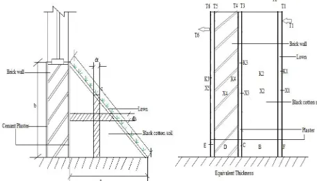
2.Lawn plus black cotton soil, brick wall with plaster on either side
3. Lawn plus porous soil, brick wall with plaster on either side
These composite materials are further analysed for techno-economical feasibility.
It is review that, the composite system of l lawn plus lateral soil, external plastering, brick wall, is better suited for low cost and durable passive solution for hot and dry climate .Design guidelines are provide for its applications to other climate zones
Keywords- earth berming, thermal balance, passive wall, wall cooling effect, wall thermal analysis, wall and comfort analysis.
1.Introduction:-The physical manifestation of some of the concepts of energy conservative land scapes designs and building configuration can reduce heat gain or act as thermal storage in solar passive architecture .It is observed that in an average building envelope total heat inside is maximum from two side depending up on the climate zones and the geographical position.. The analytical studies and application of thermal concepts can be applied for
performance evaluation of heat loads, either gain or loss from the space to be considered for passive designs with the target w.r.t comforts in side. This work therefore is concentrated on composite structure that incorporates wall and earth filling by land scapeing concept with different natural means and materials so as to minimise the heat loads.
2. The earth bearming composite materials, Composite materials (also called composition materials or shortened to composites) are materials made from two or more constituent materials with significantly different physical or chemical properties, that when combined, produce a material with characteristics different from the individual components. The individual components remain separate and distinct within the finished structure. The new material may be preferred for many reasons: common examples include materials which are stronger, lighter or less expensive when compared to traditional materials. For case study the three composite structures considered are as under;
A Lawn plus lateritic soil, brick wall with plaster on either side.
Fig no: 1 Lawn Plus lateritic soil, brick wall with plasterer on both side and equivalent wall thickness.
IJISET - International Journal of Innovative Science, Engineering & Technology, Vol. 1 Issue 7, September 2014.
www.ijiset.com ISSN 2348 – 7968
B Lawn plus black cotton soil, brick wall with plaster on either side.
Fig no: 2 Lawn plus black cotton soil, brick wall with plaster on both side and equivalent wall thickness.
C Lawn plus porous soil, brick wall with plaster on either side
Fig no: 3 Lawn plus porous soil, brick wall with plaster on both side and equivalent wall thickness. 3. Thermal analysis
Abbreviations A= Surface Area (m2)
Ai = Area of the ith Transparent Element (m2) B = Soil (m3)
C = Extarnal Plastering (m2) C = Specific Heat of Air (J/ kg-K) D = Brick Mashnari (m3)
E = Internal Plasterig (m2) F = Lawn (m2)
K1 = Thermal Conductivity of lawn (w/m2-K) K2 = Thermal Conductivity of soil (w/m2-K)
K3 = Thermal Conductivity of Extarnal Plastering (w/m2-K)
K4 = Thermal Conductivity of Brike wall (w/m2-K) K5 = Thermal Conductivity of Internal Plasterig (w/m2-K)
kj = Thermal Conductivity of its Material(W/m2-K) L= Latent Heat of Evaporation (j/kg-k)
Lj= Thickness Layer (m)
M = Number of Transparent Elements Nc = Number of Components
Q conduction = Rate of Heat Conduction (w) Q evaporation = Rate of Evaporation (w) Qventilation = Heat flow Rate Ventilation (W) Sgi = Daily Average Value of Solar Radiation (including the effect of shading) on the ith transparent element (W/m2)
T1 = Temperctur of Out side of Earth Berming (K) T2 = Temperctur of Lawn (K)
T3 = Temperctur of Soil (K)
T4 = Temperctur of External Plaster (K) T5 = Temperctur of Brick wall (K) T6 = Temperctur of Internal plaster (K) Tf = Temperature of the fluid (K) Ti = Indoor Temperature (K)
To = Daily Average Value of Hourly Ambient Temperature (K)
Ts = Temperature of the surface (K) Tso = Solar-air Temperature RT = Total Thermal Resistance
Ts = Daily Average Value of Hourly Solar Radiation Incident on the Surface (W/m2)
X1 = Tikanes of Lawn (m) X2 = Tikanes of Soil (m)
X3 = Tikanes of Extarnal Plastering (m) X4 = Tikanes of Brick wall (m)
X5 = Tikanes of Internal Plasterig (m) U = Thermal Transmittance (W/ m2- K) Vr = Ventilation Rate (m3/ s)
a = Base of Earth Berming. (m) b = Hight of Earth Berming (m) c = Digonal lenth of Eath Berming (m) h = Heat Transfer Coefficient (W/m2-K) hi = Inside Heat Transfer Coefficients(w/m2-K) ho= Outside Heat Transfer Coefficients (W/m2-K) i = Building Element.
m = Rate of Evaporation (kg/s)
R = Difference between the long wavelength radiation incident on the surface from the sky and the surroundings, and the radiation emitted by a black body at ambient temperatureΔT = Temperature difference between inside and outside air (K).
∆
T = Temperature difference (T
o– T
i) (K)
s = Mean Absorptive of the Spaceɛ
=Emissivity of the Surface (m2).
Density of air (kg/ m3)
i=
transitivity of the ith transparent elementIJISET - International Journal of Innovative Science, Engineering & Technology, Vol. 1 Issue 7, September 2014.
www.ijiset.com ISSN 2348 – 7968
The thermal analysis is worked out based on heat and mass transfer equations from ref (1). The thermal loads are calculated considering heat transfer by conduction, convection, radiation, evaporation etc. and further helps optimize the sizes .areas ,type of constructions ,structures, building forms in building passive design practices.
The Methodology developed for thermal analysis is as under
1) Define heat load. From sides
2) Selection of various materials and compositions. 3) Equivalent thickness of earth berming
4) Analysis of varies soil thickness.
It is necessary to define exactly from which side the thermal loads are maximum so that energy conservation means can be applied .Table 1. Gives Solar Radiation and Heat Load in month of December for a given location in hot and dry zone.(Latitude 18º32' Longitude 73º51' in India –ref [ 1 ] )
Sr No Solar Radiation
w/m2
Directi on
Area m2
Load watt
1 205 Roof 1 138.99
2 213 South 1 240
3 110.6 East 1 200.38
4 44.5 North 1 162.8
5 111.66 West 1 238.32
Total 980.49
Pie Chart as shown in fig 1 can be futher be used for understanding % loads in terms of intensity per unit of area .
1 Fig 4 –Representative pie diagram for load analysis
3.1 Heat transfer and heat balance at Earth
Berming by conduction, convection, and
evaporation etc.
3.1.1. Heat Transfer by Thermal transmittance Q conduction = AU ΔT --- (1) It may be noted that the steady state method does not account for the effect of heat capacity of building materials.
U is given by
U=1/R
T--- (2)--- (3)
hi and ho respectively, are the inside and outside heat transfer coefficients of the and
U indicates the total amount of heat transmitted from outdoor to indoor space through a given wall or brick wall per unit area per unit time. The lower the value of U, the higher is the insulating value of the element. Thus, the U-value can be used for comparing the insulating values of various building elements.
Equation is solved for every external constituent element of the building i.e., each composite materials as described in above. The over al heat flow rate through the building envelope is expressed as:
--- (4)
If the surface is also exposed to solar radiation then
,
∆T = Tso – Ti --- (5)--- (6) 3.1.2 Ventilation The heat flow rate due to ventilation of air between the interior of a building and the outside depends on the rate of air exchange. It is given by
:
Qv = ρ Vr C ∆T --- (7)
3.1.3 Solar Heat Gain The solar gain through transparent elements can be written as
:
--- (8) 3.1.4 Internal Gain Thus the heat flow rate due to internal heat gain is given by the equation:
Qroof 14%
Qsouth 25%
Qeast 20% Qnorth
17% Qwest
24%
IJISET - International Journal of Innovative Science, Engineering & Technology, Vol. 1 Issue 7, September 2014.
www.ijiset.com ISSN 2348 – 7968
Qi = (No. of people × heat output rate) + Rated wattage of lamps + Appliance load --- (9) 3.1.5 Evaporation generally refers to the removal of water by vaporisation from aqueous solutions of non-volatile substances. It takes place continuously at all temperatures and increases as the temperature is raised. Increase in the wind speed also causes increased rates of evaporation. The latent heat required for vaporization is taken up partly from the surroundings and partly from the liquid itself. Evaporation thus causes cooling.
Q evaporation = m x L --- (10) 3.1.6 Equipment Gain If any mechanical heating or cooling equipment is used, thΣe heat flow rate of the equipment is added to the heat gain of the building.
3.1.7 Heat balance equation
Q total = Q c + Q v +Q s +Q i + Q ev + Q equ --- (11)
Q v , Q i , Q equ , this value are negligible in earth
berming system.
Q total = Q c+ Q ev --- (12)
--- (13)
Put value of Ai Ui ∆T in equ 13
4. Analysis .The equations are solved for triangular shaped earth berming system with main composite
materials using , Lawn, Lateritic soil Black cotton soil and porous soil. The graphs are plottes as under for comparison of different composites.
Graph No1 Lateritic Soil, Black cotton Soil, Porous Soil, Thickness Change (m) Vs In Said Soil Temperature(K).
Graph No 2 Lateritic Soil, Black cotton Soil, Porous Soil, Thickness Change (m) Vs Transmittance Value (U) W/m2-K
22 23 24 25 26 27 28 29
0.
7
0
.7
5
0.
8
0
.8
5
0.
9
0
.9
8
11
.0
5
1.
1
1
.1
5
In
sa
id
S
o
il
T
em
pr
a
tur
e
(K
)
Soil Thickanes (m)
T3 Vs X2
Lateritic Black cottonporous
22 23 24 25 26 27 28 29
In
sa
ids
o
il
T
em
pe
ra
tur
e
(K
)
U Value
U value Vs Temperature
lateriticBlack Cotton porous
IJISET - International Journal of Innovative Science, Engineering & Technology, Vol. 1 Issue 7, September 2014.
www.ijiset.com ISSN 2348 – 7968
Graph No 3 Lateritic Soil, Black cotton Soil, Porous Soil, Thickness Change (m) Total Thermal Resistance (R Value) Vs Insaide soil Temperature (K)
Graph No 4 Lateritic Soil, Black cotton Soil, Porous Soil, Thickness 1.15 (m) Out Said Soil Temperature (K) Vs In Saide Soil Temperature (K)
Graph No 5 Lateritic Soil, Black cotton Soil, Porous Soil, Thickness 0.98 (m) Out Said Soil Temperature (K) Vs In Saide Soil Temperature (K)
Graph No 6 Lateritic Soil, Black cotton Soil, Porous Soil, Thickness 0.90 (m) Out Said Soil Temperature (K) Vs In Saide Soil Temperature (K)
22 23 24 25 26 27 28 29
In
sa
ide
so
il
T
em
pe
ra
tur
e
(K
)
Total Thermal Resistance (RValue)
R value Vs Temperature
Lateriticblack cotton
Porous
21 22 23 24 25 26 27 28
35 36 37 38 39 40 41 42 43 44
In
sa
ide
so
il
T
em
pe
ra
tur
e(K
)
Out said Temperature (K)T1 Vs T3
LateriticBlack Cotton Porous
21 22 23 24 25 26 27 28 29
35 36 37 38 39 40 41 42 43 44
T3
T1T1 Vs T3
LateriticBlack Cotton Porous
21 22 23 24 25 26 27 28 29
35 36 37 38 39 40 41 42 43 44
T3
T1T1 Vs T3
LateriticBlack Cotton Porous
IJISET - International Journal of Innovative Science, Engineering & Technology, Vol. 1 Issue 7, September 2014.
www.ijiset.com ISSN 2348 – 7968
5. Recommendations and conclusion
The use of earth berming techniques is theoretically evaluated for its performance by doing the thermal balance using thermal transmittance method. The three case studies taken are use of porous soil, black cotton soil and lateritic soil,embedded between the inside wall and the lawn at outer surface.The new method adopted for performance is useful for designing earth berming system by thermal balance. The triangular shape is further optimized by varying width and height the earth berming triangle. Further it is noted that earth berming with lateritic soil is most suitable to achieving the comfort inside building.
6. References
1) J.K. Nayak And J.A. Prajapati ; “Handbook On Energy Conscious Buildings” Prepared Under The Interactive R & D Project No. 3/4(03)/99-Sec Between Indian Institute Of Technology, Bombay And Solar Energy Centre, Ministry Of Non-Conventional Energy Sources; May 2006.
2) M. Staniec, H. Nowak; “Analysis Of The Earth-Sheltered Buildings”; Heating And Cooling Energy Demand Depending On Type Of Soil Vol. Xi 2011, P.P.1-15.
3) R.K.Rajput “Heat and Mass Transfer” S.Chand And Company Pvt Ltd. (An Iso 9001:2008 Company)
4) E.A. Rodriguez S. Alvarez, Ph.D. “Heat Transfer Analysis of Ground-Coupled Structures”
5)Pawłowski Aleksander, Heim Dariusz Hensen Jan “Ground Source Heat Pumps Designed For Low-Energy, Earth-Sheltered Atrium Building”
6)
Staniec M.: “Analysis of the influence of earth sheltering on the building’s energy balance” (in Polish), PhD Thesis, Series PRE No. 01/09, WrocławUniversity of Technology, 2009.
7
) Maja Staniec1, Henryk nowak1 “Analysis of The Energy Performance of Earth-ShelteredHouses with Southern Elevation Exposed” 2009 Eleventh International IBPSA Conference8)
G. P. Mitalas Basement “Heat Loss Studies at DBR/NRC” Division of Building Research 1982Research Fellow
Prafull Prakash Tayshete.
Department of Energy Technology;
Department of Technology;
Shivaji University Kolhapur
IJISET - International Journal of Innovative Science, Engineering & Technology, Vol. 1 Issue 7, September 2014.
www.ijiset.com ISSN 2348 – 7968