Application of the erosion algorithm in modeling of
struc-tures behavior under impulse loads
PavelRadchenko1,StanislavBatuev1,∗, andAndreyRadchenko1
1Tomsk State University of Architecture and Building
Abstract.The paper presents results of applying approach to simulation of con-tact surfaces fracture under high velocity interaction of solid bodies. The algo-rithm of erosion - the algoalgo-rithm of elements removing, of new surface building and of mass distribution after elements fracture at contact boundaries is con-sider. The results of coordinated experimental and numerical studies of fracture of materials under impact are given. Authors own finite element computer soft-ware program EFES, allowing to simulate a three-dimensional setting behavior of complex structures under dynamic loads, has been used for the calculations.
1 Introduction
Description of materials fracture in the area of contact interaction is a challenging issue in numerical simulation of high-velocity interaction of solid bodies. High-velocity loading in-duces occurrence of the areas with intensive fracture of interacting bodies. Local distortion of computational mesh can lead to both fall of step size over time as well as to the struc-tural failure of computational mesh. Generally it is suggested to remove the fractured finite elements out of numerical calculation.
Current research related to this issue offer various computational mesh adaptive algo-rithms [1–3]. Contact problems are solved using different numerical approaches [4–6]: La-grange multiplier method, penalty and regularization method, quadratic programming, mod-ifications of Newton method, Schwarz decomposition method, pseudo-medium, and others. Multiple algorithms modify the mesh only in two-dimensional case [7]. Parallel computations have recently become of great concern while developing and modification of finite-element meshes [8].
When solving the objective of solid bodies’ penetration an extensive area of fractured material is being formed inside the barrier crater; this area influences significantly the step size over time for the evident calculation models. In such case removing of elements and nodes with mass influences negatively the validity of solution; previously authors suggested the recalculation algorithm for local mass in the nodes of computational mesh providing high-quality description of objectives of solid bodies’ dynamic loading [9].
Currently there are several commercial program software based on parallel computations and used for calculation of stress-strain state and materials and structures fracture under dy-namic loading, among them are ANSYS, ABAQUS, LS-DYNA. Software developers try to endow them with multiple-purpose functions and adjust software for solving a wide range
of objectives. Against this background it leads to “complication” of the algorithm and loss of efficiency. Loss of efficiency in this case is conditioned by impossibility to make all the processes parallel. In particular this refers to modeling of dynamic fracture of geometrically complex structures with a large number of contacting boundaries [10] .
Compared with other programs, EFES software developed by the authors has a number of significant advantages:
• it uses original algorithm which is optimized to the maximum extent to calculate the con-tacting boundaries; this is especially relevant while analyzing the structures of complex geometry;
• it implements the mechanism of “erosion” of contacting elements, thus enabling to keep the regularity of finite element grid at the acceptable integration step;
• there are no limitations on the number of processors (cores) and the number of finite ele-ments; as a rule there are such limitations in other programs.
2 Mathematical model
Program software is based on three-dimensional approach to behavior of materials and struc-tures. The set of equations describing non-stationary adiabatic motions of compressible medium in general coordinates (i=1,2,3), includes the following equations [11]:
1) continuity equation
∂ρ ∂t +ρ∇iυ
i=0, (1)
2) motion equation
ρak=∇iσik+Fk, (2)
where
ak=∂υ k
∂t +υ i∇
iυk,
∇iσik=σik,i + Γ k imσ
im+ Γm imσ
ik,
3) energy equation
dE dt =
1
ρσi jei j. (3)
WhereFkis components of mass force vector;Γki j– Christoffel symbols;σi j– contravariant components of symmetric stress tensor; E – specific internal energy; ei j – components of symmetric strain velocity tensor:ρ– density of medium; ¯υ– velocity vector;ak– components of acceleration vector;
ei j= 1 2
∇iυj+∇jυi. (4)
The behavior of the metals are described by an elastoplastic model. Stress tensor is presented as a sum of deviatoricSkiand spherical partP:
σi j =−Pgi j+Si j, (5)
where gi j – metric tensor. Pressure inside the materials has been calculated using Mie-Gruneisen equation as a function of specific internal energyEand densityρ:
P= 3
X
n=1 Kn
V V0
−1
!n"
1−K0 V V0 −1 ! /2 #
whereK0,K1,K2,K3 – material constants,V0 – initial specific volume,V – current specific volume.
Suppose that the principle of minimum work of true stresses on the increments of plastic deformations is true for the medium, than the connection of component of strain velocity tensor and stress deviator is as follows:
2G gimgjkemk− 1 3g
mke mkgi j
!
= DSi j Dt +λS
i j, (λ≥0), (7)
In this case time derivatives of stress tensor are accepted by Jaumann definition:
DSi j Dt =
dSi j dt −g
imω
mkSk j−gjmωmkSik,
whereωi j=12
∇iυj− ∇jυi,G– shear modulus.
Consider that material behaves in elastic manner (λ=0), in case when von Mises criterion is followed:
Si jSi j≤ 2 3σ
2
d, (8)
and it behaves in plastic manner (λ > 0), when the criterion is not followed. Hereσd – dynamic tensile yield stress that can in the general case be the function of deformations ve-locity, pressure and temperature. In case the condition (8) is violated, we apply the procedure of correction of stresses considering the material plasticity for calculation of the component of stress deviator. Components ofSi j are multiplied by normalizing factor, that equals to description of medium behavior in plastic zone as proved by equations of Prandtl-Reuss.
Limiting value of plastic strain intensity is accepted as a local criterion of shear fracture in metals:
eu= √
2 3
q
3T2−T12, (9)
whereT1,T2- first and second invariants of strain tensors.
It is suggested that fracture in conditions of intensive dynamic loads occurs the following way: - in case strength criterion (9) is violated under conditions of compression (ekk ≤ 0), than further material behavior is described by hydrodynamic model; - in case criterion (9) is violated under conditions of tension (ekk >0), than material is considered to be completely destructed and components of stress tensor are supposed to be equal to zero.
Important aspect while numerical modeling of impact interaction is selecting the algo-rithm of contact boundaries calculation. Generally, the existing program software use al-gorithms “element-node” and “node-node” to define the possible penetration of one body into another. The given work suggests the algorithm of “element-element” type [12], proved oneself to be appropriate while solving the three dimensional objectives and enabling to use possibilities of parallel computing to a maximum extent.
3 Erosion algorithm
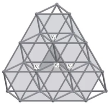
element being on the contact surface. Let us consider the elementE1, which is formed by the nodesN1N2N3N4 (Fig. 1). When following the criterion of fracture in finite element on the surface of a solid body, this element is removed from the computational grid (Fig. 1). The elementE1had mutual planes with the elementsE5,E9,E13, after removal of the elementE1 from the grid, the new surface triangles are being built:N1N2N4,N1N4N3,N2N3N4(Fig. 2).
Figure 1.Three dimensional finite element mesh.
Figure 2.Three dimensional finite element mesh after removal of the elementE1.
Even using parallel computations this algorithm still requires rather long time. For in-stance, on 64-core workstation with the loading of all computing threads solution of objective with the mesh of 30 mln elements is completed within 15 days.
4 Calculation results and their comparison with experimental data
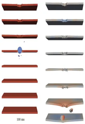
Figure 3 shows computational configuration of projectile in section, which is sphere-shaped made from steel ShKh15, of diameter 12.7 mm and barrier made from alloy D16T, 4.9 mm thick at sequential points in time. Initial velocity of projectile is 1001 m/s, velocity vector makes angle of 60 degrees with normal to the barrier. Calculations demonstrate the dynamics of barrier fracture and formation of fragment field at the back surface of the barrier.
Figure 4 demonstrates experimental and calculated hole in the barrier after interaction with projectile. Experimental and numerical results find good qualitative and quantitative correspondence. The largest diameter of the hole during the experiment comprises 26.6 mm, the calculated value comprises 26.9 mm (relative discrepancyδ=1.1%). The value of pro-jectile velocity after barrier penetration makes 843 m/s, the calculated value makes 846 m/s (δ=0.4%).
Figure 3.Calculated configurations of projectile and barrier
Figure 5 shows calculated configurations of sphere-shaped projectile under normal inter-action with spaced barrier from eight plates. Projectile is made from steel ShKh15; material of spaced barrier is alloy D16T. Plates in the barrier are 2.8 mm thick, projectile diameter is 9.5 mm. Initial velocity of projectile is 1010 m/s. In this case the projectile penetrates seven barriers and stops at the eight’s one, forming crater inside it. Crater diameter comprises 8 mm in the experiment and 7.2 mm in the calculation (δ=10%). Experimental and computational results of projectile velocity after penetration of the first barrier have been also compared: the experimental value is 925 m/s, the calculated one is 912 m/s (δ=10%). Diameter of the hole in the first barrier in the experiment makes 9.4 mm, in calculation – 9.5 mm (δ=1%).
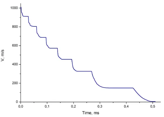
Figure 6 shows calculated dependency of center-of-mass velocity of projectile in time. It is characterized by row echelon form; areas of heavy breaking correspond to the period of projectile interaction with plates of spaced barrier.
Figure 6.Time variation of center-of-mass velocity of projectile.
5 Conclusions
Resulting from the conducted studies it can be concluded that:
• The suggested algorithm for calculation of contact boundaries enables solving multiple contact objectives of deformable solid bodies’ interaction considering their fracture and fragmentation.
• The implemented algorithm and calculation methodology enables to study behavior of sep-arate elements and whole structures in three dimensional dynamic setting.
• Based on the developed methodology it is possible to conduct multiple-parameters numer-ical experiments to select optimal structural solutions.
• Application of erosion fracture algorithm is necessary for the proper description of fracture propagation processes during high-velocity interaction of solid bodies.
• Application of parallel computations enables to reduce the calculation time substantially.
The work has been conducted with the financial support of the Russian Foundation for Basic Re-search (projects No. 18-48-700035 and 18-41-703003) and the grant of the Ministry of Education and Science of the Russian Federation (project # 9.6814.2017/BP).
References
[1] S. Renev, S. V.V., Marine Intellectual Technologies3, 72 (2017)
[3] V. Yadrov, Omsk Scientific Bulletin3, 152 (2014)
[4] N. Bourago, V. Kukudzhanov, Mechanics of Solids40, 35 (2005)
[5] T. Laursen, Computational contact and impact mechanics: fundamentals of model-ing interfacial phenomena in nonlinear finite element analysis, Vol. 40 (New York: Springer, 2003)
[6] A. Karavaev, S. Kopytov, The Bulletin of Udmurt University. Mechanics.27, 396 (2017) [7] A. Lukashevich, The Bulletin of Pacific National University4, 69 (2007)
[8] K. Andre, O. Gluschenko, E. Ivanov, A. Kudryavtsev, Computational Mathematics and Mathematical Physics48, 1448 (2008)
[9] P. Radchenko, S. Batuev, A. Radchenko, AIP Conference Proceedings (2018)
[10] P. Radchenko, S. Batuev, A. Radchenko, Advanced Materials Research 1085, 486 (2015)
[11] P. Radchenko, S. Batuev, A. Radchenko, Key Engineering Materials 592-593, 287 (2014)