CFD and Experimental Analysis of
Catalytic Converter to Optimize the Effect of
Back Pressure
Likesh A. Dahake 1, S.P.Komble 2, Dr. D.B. Hulwan 3
P.G. Student, Department of Mechanical Engineering VIT, Pune, Maharashtra, India1. Assistant Professor, Department of Mechanical Engineering VIT, Pune, Maharashtra, India2. AssociateProfessor, Department of Mechanical Engineering VIT, Pune, Maharashtra, India3.
ABSTRACT: Now a days ,diesel emission control rule are more strict across whole world that's why there is need of diesel after treatment devices which are more reliable and efficient with optimum performance. To meet these requirement there must be effective use of simulation tool like computational fluid dynamics(CFD) in designing and performance evaluation . The objective of the present project is to design and test a Diesel Oxidation Catalyst which will minimize the back pressure and pressure drop of DOC and maintained it within range. The design of the DOC was made by the calculations based on the continuity equation which is the law of conservation of mass. The calculated dimensions were used to make the DOC thus proposed was used for experimentation and its results were noted. The experimentation was done on Kirloskar, Model TV1, Type Single cylinder, and 4-stroke diesel engine. Simulation results were then compared with the experimental results for validation.
KEYWORDS: Engine emissions, Catalytic converter, CFD, Backpressure, and Fuel Consumption.
I. INTRODUCTION
After treatment of exhaust gases is the simple and the most effective source to reduce NOx and PM of diesel engine emission.Diesel oxidation catalyst (DOC) is the most effective after treatment device in automobile and other engines. The catalyst (alloys of high thermal stability materials) is placed inside the DOC due to this there is increase in back pressure. This increase in back pressure causes more fuel consumption, one can say that the presence of DOC increase back pressure in engine. The power required to impel the exhaust gases through exhaust port is called the exhaust stroke loss. It is observed that increase in speed increases the exhaust stroke loss. During the exhaust stroke when the piston moves from bottom dead centre( BDC) to top dead centre(TDC), pressure rises and gases are pushed into exhaust pipe through exhaust valve. Net work required to pushed out exhaust gases called pumping work. The net work output per cycle from the engine is dependent on the pumping work consumed, which is directly proportional to the backpressure hence to reduce the pumping work, the backpressure must be low as possible for obtaining the maximum output from the engine. The backpressure depends on design and size of DOC. Therefore after treatment devices and exhaust system components must be designed for minimum backpressure so that it should be more reliable and efficient with optimum performance. [1] Also, design of catalytic converter has direct impact on the backpressure. The backpressure has direct relation with catalytic substrate and shape of the inlet cone. It observed that an engine will lose about 300W to 350W of power per 1000 Pa of backpressure. [2]
necessary to find the best substitution between oxidizing carbon monoxide and hydrocarbons without increasing nitrogen dioxide. [7]
II. DETAILS OF DIESEL OXIDATION CATALYST
Different types of catalyst(filter) material used in internal combustion engine. Mostly categorized in metallic and non-metallic. Non- metallic are Ceramic monolith, ceramic foam, ceramic silicon fiber, porous ceramic honey comb and metallic includes steel wire meshes.[4] Metallic catalyst substrates are made of thin metal foils, flat and corrugated formed into a honeycomb structure which is placed inside a metal shell. Generally these are made of thin metal foils of ferritic iron-chromium-aluminum alloys of high thermal durability. metal substrates have advantage of high geometric surface area and low pressure drop compared to non-metallic substrates.re. The foils in metallic substrates can be easily brazed or welded together to provide good mechanical durability and resistance to thermal shock.
Figure 1. Metallic Substrate [5]
Cylindrical shaped substrates can be assembled to improve exhaust gas flow distribution through the converter Metallic substrates have been more commonly utilized for diesel aftermarket/retrofit converters. Another common application of metallic substrates is catalytic converters for stationary engines. high cost is the only major issue with metallic substrate. [6]
Details of the substrate are as follows Material – Metallic
Diameter – 60 mm Length – 150 mm Cell Density – 300 cpsi
III. CFD ANALYSIS
A) CFD METHODOLOGY
CAD model of DOC is made in Creo Parametric 2.0. This model was simulated in CFD software. For the CFD analysis software used is STAR-CCM+.
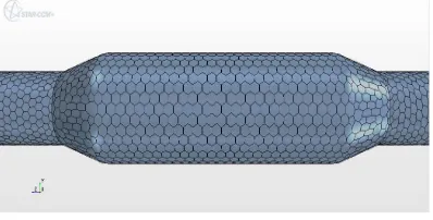
1) Modeling and Meshing
substrate etc. Surface Remesher, Automatic Surface Repair, Polyhedral Mesher, Prism Layer Mesher are used for meshing.
Figure 2: Mesh Scene in STAR-CCM+ 2) Physics model
CFD solver Star CCM+ is used for this study. It is a finite volume approach based solver which is widely used. In the Physics continuum, the initial conditions have to be given. The conditions include Pressure, Static temperature and Velocity. High Reynolds number k-ɛ turbulence model is used in the CFD model. [3]. After the Physics conditions, the Initial Boundary conditions at region level are defined as given below
Inlet Face = Velocity inlet Outlet face = Pressure Outlet Substrate = Porous Region Rest all surfaces = Wall.
Figure 3: Model of with inlet, outlet and substrate in STAR-CCM+.
In above figure shows CFD software view of model with inlet, outlet and substrate location. Following Inlet boundary conditions are used for the DOC analysis
Working Fluid: Exhaust Gas (Density=0.507kg/m3, Viscosity = 3.58e-5 kg/m-s) Inlet Conditions: Mass flow rate 25.29 kg/hr @ 375° C, Velocity=6 m/s
Outlet Condition: Open to atmosphere (approx 0 Pa). Porosity : 0.8
B) CFD results
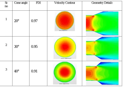
1) Effect of inlet cone angle
Flow gets channelize gradually as per cone angle and this avoids flow separation from wall which could happen with large cone angle. Inlet and outlet cone angle of DOC has direct effect on flow distribution index
.
Figure 4: Flow distribution index for different cone angle
From above figure shows flow distribution index of velocity profile inside substrate for different inlet and outlet cone angle of DOC.
Table 1: Geometry with different cone angle and its corresponding FDI 0.9
0.95 1
0 20 40 60
FD
I
CONE ANGLE
FDI
FDI
Sr no
Cone angle FDI Velocity Contour Geometry Details
1
20°
0.97
2
30°
0.95
3
From the above CFD analysis of different cone angle, it shows that maximum Flow distribution index with 20° cone angle than 30° and 40° cone angle, therefore 20° inlet and outlet cone angle is used for the fabrication of catalytic converter.
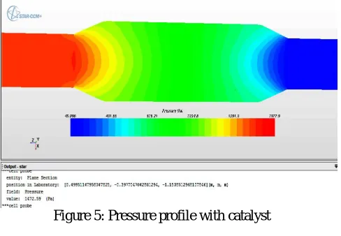
2) Back pressure
It is the diesel engine that pumps the gas by compressing it to a sufficiently high pressure to overcome the flow obstructions in the exhaust system. We know to minimize the pumping work, backpressure must be low as possible. The net work output per cycle from the engine is dependent on the pumping work consumed. pumping work is directly proportional to the backpressure. An engine will lose about 300 W of power per 1000 Pa of pressure loss.
While observing back pressure from CFD simulation we need to check reading of pressure before inlet of DOC with catalyst and also need to take reading of pressure at same location without catalyst. This difference in pressure gives us simulated back pressure.
Figure 5: Pressure profile with catalyst
Figure 6: Pressure profile without catalyst
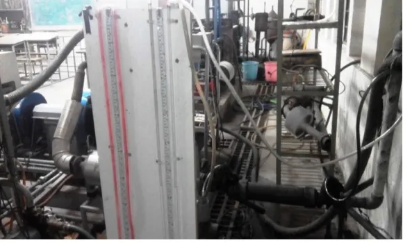
IV. EXPERIMENTAL ANALYSIS
The experimentation was done on Kirloskar, Model TV1, Type Single cylinder, 4-stroke diesel engine. The setup consists of engine connected to eddy current type dynamometer for engine loading. The setup has stand-alone type independent panel box consisting of air box, fuel tank, and manometer, fuel measuring unit, digital speed indicator and digital temperature indicator. Engine jacket cooling water inlet, outlet and calorimeter temperature is displayed on temperature indicator, U-tube manometer is used to measure pressure. Rotameters are provided for cooling water and calorimeter flow measurement. The setup enables study of engine for brake power, BMEP, brake thermal efficiency, volumetric efficiency, specific fuel consumption, air fuel ratio and heat balance.
Figure 7: Experimental set-up of Engine exhaust system
A) Procedure of experimentation
Ensure cooling water circulation for eddy current dynamometer, engine and calorimeter. Start the set up and run the engine at no load for 4-5 minutes.
Gradually increase the load on the engine by rotating dynamometer loading unit.
Wait for steady state (for 3 minutes) and collect the reading as per Observations provided in “Cal225” worksheet in “Engine.xls”.
Note down pressure readings from u-tube manometer. Note down Gas analyser readings.
Repeat the process for different load with constant compression ratio. Gradually decrease the load.
Change Compression ratio.
Repeat the procedure, Note down readings for different Compression ratio
Fill up the observations in “Cal225” worksheet to get the results and performance plots.
B) Experimentation Result
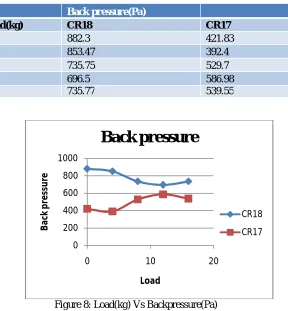
Table 2: Back Pressure for different CR
Back pressure(Pa)
Load(kg) CR18 CR17
0 882.3 421.83
4 853.47 392.4
8 735.75 529.7
12 696.5 586.98
16 735.77 539.55
Figure 8: Load(kg) Vs Backpressure(Pa)
From above figure we can observed that actual backpressure is in the range of 400 to 900 Pa. which is
acceptable.
V. CONCLUSION
From CFD analysis we get 559.507 Pa back pressure by knowing the difference between pressure with catalyst and without catalyst at inlet. It is observed that value of back pressure got by CFD is nearly same as experimental back pressure value. The amount of backpressure we get by both CFD analysis as well as experimentally is less, and thus the net work output per cycle from the engine which is dependent on the pumping work consumed, (which is directly proportional to the backpressure) is less when we used DOC.
In this paper, one can observed that with use of CFD analysis, effective utilization of DOC by reducing power loss(pumping power) because of backpressure and also designing of DOC with proper inlet cone angle (catalyst) for the optimization of flow of exhaust gases to increase flow distribution index.
While using CFD, it can observed that with proper simulated parameters, such as inlet boundary condition, appropriate dimension of catalyst and suitable location of DOC, the effectiveness of engine will be improved without hampering emission standard. We can implement this type of analysis to different kinds of engine.
0 200 400 600 800 1000
0 10 20
REFERENCES
[1] Nagalli Raghu, G.V.Devra, Jai Sagar, "Experimental Analysis on Catalytic Converter Using CFD", International Journal of Innovative Research in Science,Engineering and Technology,Vol. 4, Issue 7, July 2015,5251-5261
[2] P.Karuppusamy1, Dr. R.Senthil, "Design, Analysis Of Flow characteristics Of Catalytic Converter and effects Of Backpressure On Engine Performance", International Journal of Research in Engineering & Advanced Technology, Volume 1, Issue 1, March, 2013.
[3] Muthaiah, P. L. S., Dr. Senthil Kumar M., Dr. Sendilvelan S., “CFD Analysis of catalytic converter to reduce particulate matter and achieve limited back pressure in diesel engine”, Global journal of researches in engineering – A: Classification(FOR), Vol.10, Issue 5 (Ver1.0), pp. 091304 - 091399, October 2010.
[4] H.Maheshappa,V.K.Pravin, K.S.Umesh, P.H.Veena, "Design Analysis of Catalytic Converter to reduce Particulate Matter and Achieve Limited Back Pressure in Diesel Engine By CFD‖, International Journal of Engineering Research and Applications, Vol.3, Issue 1, January -February 2013, pp.998-1004.
[5] http://www.emitec.com/en/technology/catalyst-substrates/ [6] https://www.dieselnet.com/
[7] http://www.blackthorn.net/substrates/