Performance of SI Engine at Various of Oil
Catch Tank Filter Materials
Budi Waluyo1, Saifudin2
Lecturer, Department of Automotive Engineering, Muhammadiyah University of Magelang, Magelang, Indonesia1,2
ABSTRACT: The main problem SI engine with a positive crankcase ventilation system (PCV) is the formation of carbon crust due to the evaporation of the lubricating oil. This condition will cause engine knocking as well as performance decreases.This problem can be reduced by adding oil catch tank between the PCV valve and the induction chamber. This research aims to select the type of filter OCT to generate the optimal engine performance.Engine performance is indicated by decreasing of hydrocarbons and carbon monoxide emissions. While decreasing engine knocking is indicated by the coolant temperature. Water, natural zeolite and the urethane foam were used as a filter to determine which type of filter OCT generate the optimum engine performance. The coolanttemperature and the exhaust emissions were measured at the engine speed of 750, 1500, 2500 and 3000 rpm.The results of this study show that zeolite filter has the most optimum performance in all engine speed conditions.
KEYWORDS: filter, oil catch tank, engine performance
I. INTRODUCTION
Nowadays, the air quality issues has been major problems, especially in large urban areasdue to the high car population particularly in urban region[1]. Emissions are the terms of the release of gases and particles into the environment that's undesirable. Crankcase gasses are harmful emissions because it contains un-burning hydrocarbon gas. Positive crankcase ventilation system mitigates environment impact by mixing the crankcase gas and clean air in the induction chamber. However, the use of positive crankcase ventilation system at the old car with a high degree of wear actually caused new problems. In the old car, high oil vapour is due to the blow-by gas. Carbon crust formation in the combustion chamber will occur more quickly. It’s due to the engine oil vapour into the combustion chamber. The crust of carbon in the combustion chamber will cause engine knocking. Meanwhile, engine knocking in an internal combustion engine tends to decrease of engine performance.
The combustion process in the internal combustion engine (IC Engine) produce carbon dioxide (CO2) and water vapour (H2O)[2]. In addition, in case of incomplete combustion of IC Engine produce carbon monoxide (CO) and hydro carbon (HC) emissions. One of the efforts to reduce air pollution from IC Engine is known by applying the positive crankcase ventilations(PCV) systems.This system serves to protect the environment effect from emissions of crankcase consisting such asengine oil vapour, water vapour, and other gas that enter back into the intake manifold and burned in the combustion chamber[3].However, vapour oil has long chain carbon which will cause incomplete combustion, so it increases emissions in IC engine.
II. RELATED WORK
In the last decade,synthetic oil is produced to meet the needs of the oil with high performance. Synthetic oil has better performance compared with natural oil. It's designed to produce a more effective performance than the mineral oil.however, synthetic base oil include poly alpha olefin (PAO), poly alkaline glycols (PAG) and Alkylated naphthalene’s (AN) which they have low molecular weight. The low molecular weight will cause a problem that is more blow-by gas entering the crankcase.This condition affects the high temperature of the lubricating oil in the crankcase, thereby increasing the rate of evaporation of the engine lubricating oil.In the car with the PCV system, oil vapour will enter into the combustion chamber. Burning oil vapour will accelerate the build-up of carbon crust on the walls of the combustion chamber. This will cause engine knocking as well as reduce engine performance and lifetime of engine components.
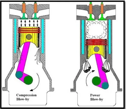
On the spark ignition (SI) engine, piston rings consist of the upper compression ring (UCR), Scrapper compression ring (SCR) and the oil control ring (OCR)[10]. Oil control ring has a three piece design that consists of the top, bottom rail and the ring expands as the support. Blow-by gas occurs during the compression and power stroke.Power blow-by gas is the hot gas combustion products into the crankcase through the gap between piston rings, piston and cylinder liner wall.While compression blow-by is a cold gas that is a mixture of fuel and air into the crankcase during the compression stroke.The phenomenon of blow-by gas in the spark ignition engine are presented in Figure I.1 as follows,
Figure Error! No text of specified style in document..1The phenomenon of blow-by gas
The hot gas combustion products into the crankcase will cause a warming lubricant, so the lubricant will be volatile. While the cool gas entering the crankcase during the compression stroke of the engine decrease the lubricant viscosity. The lower crankcase lubricant viscosity tends to evaporate at lower temperatures. On the cars with positive crankcase ventilation system, this lubricant vapour will enter the combustion chamber then will interfere with complete combustion process. The amount of blow-by gas in an engine depends on engine wear especially pistons, piston rings and cylinder liners[11].
III. MATERIAL AND METHOD
This study uses four-stroke engine four cylinder inline type. Engine under test described at the table II.1 below,
Table Error! No text of specified style in document..1Engine specification
Engine manufacturer : Toyota
Engine type : 5A-FE
Cylinders : Inline 4
Capacity : 1.498 Litres
Bore × Stroke : 78.7 × 77 mm
Valve mechanism : DOHC, 4 valves per cylinder
Maximum power output : 77 kw @ 6000 rpm
Maximum torque : 135 Nm @ 4800 rpm
Compression ratio : 9.8:1
Fuel system : EFI
This study uses natural zeolites, water and urethane foam as a filter in the oil catch tank.Test without oil catch tank is also performed as a comparison using oil catch tank with different types of filters. OCT design and filter used in this study are presented in the following Figure,
Figure Error! No text of specified style in document..2OCT design and filter used in this study
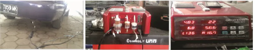
Measuring of hydrocarbon and carbon monoxide emissions using the exhaust gas analyser by Qrotech QRO-401 was chosen to determine theengine performance. Installation of exhaust emission measurements are presented in the following figure,
Engine speed and coolant temperature are measured using the Car Doctor Engine Scanner. Engine scanner as a measuring tool is able to monitor almost all the important parameters on the engine testing in real-time. An engine coolant temperature will be correlated to the trend of engine knocking. Measurement of various engine speeds is to show real working engine. The engine knocking will reduce the engine performance. The following Figure presents the scanner engine that is used in this study,
Figure Error! No text of specified style in document..4. Engine scanner used in the study
Measuring procedures and data capture on engine testing are each version machine performed five data capture.Air to fuel ratio (AFR) of the test engine is conditioned on stoichiometry (λ = 1 + 0.05).Controlling the air to fuel ratio (AFR) is aimed to avoid the effect of AFR to change the test variable.Measurements carried out at temperature and relative humidity of 28o + 2o Cand 64+ 2%, respectively.
IV.RESULT AND DISCUSSION
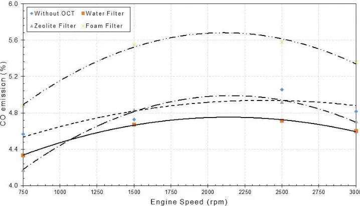
The results of emission testing carbon monoxide (CO) in various types of filters OCT is presented in FigureIII.1,
The horizontal axis is the engine speed (rpm) and the vertical axis is the emission value of CO (%). From Figure III.1 presented that at the engine speed of 750 rpm (idle speed), the lowest emissions obtained at zeolite filter of 4.2%, while the highest CO emissions are obtained from the foam filter of 4.9%. However, in the medium and high-speed, water filter at least produce CO emissions. Use foam filter for OCT showing the impact of high CO emissions in all engine conditions.
On the engine testing above 1250 rpm, the use of OCT with zeolite filter showed no significant difference in CO emissions. However, the use of OCT with water filter produces a decrease in CO emissions is more stable at high-speed. The decline in the performance of OCT with zeolite filter at high-speed is due to the active material has been saturated in the zeolite adsorbs CO emissions. At the higher engine speed, mass flow rate of CO emissions is also higher so the zeolite filter with the dimensions of the test is not able to absorb CO emissions at high-speed.
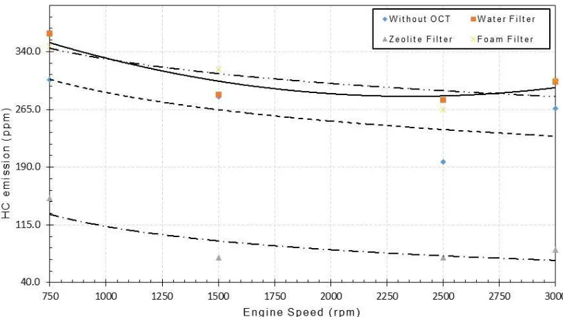
The results of hydrocarbon emissions (HC) use oil catch tank with various of filters are presented in Figure III.2 below,
Figure Error! No text of specified style in document..6HC emissions with various OCT filter
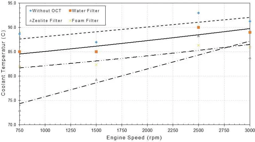
The coolant temperature results in the use of oil catch tank with a various of filters presented in the Figure below III.3,
Figure Error! No text of specified style in document..7 Coolant temperatureat various OCT filter
From Figure III.3 shows that the lowest coolant temperature is obtained from zeolite filters for almost all of engine conditions. This condition is correlated with the ability of zeolite filter in reducing emissions of HC in the figure III.2. The addition of hydrocarbons gas from the crankcase tends to enrich the AFR in the combustion chamber. AFR richer will increase the flux of heat in the engine coolant so that its temperature will be higher.
The use of oil catch tank on an engine also serves as a coolant blow-by gas flowing into the induction room. On vehicles without oil catch tank, blow-by gas flowing into the induction chamber still has a high temperature. High temperatures in the induction room will affect the volumetric efficiency is low. While the blow-by gas temperature of this cooler will improve volumetric efficiency and energy absorbing more heat of combustion in the combustion chamber.
V. CONCLUSION
In this study, carbon monoxide emissions, hydrocarbon, and coolant temperature is used as a parameter to identify the type of filter that is optimum for application in oil catch tank. The engine speed of 750, 1500, 2500, and 3000 rpm are used to represent the engine operating conditions. These results indicate that the use of zeolite filter produces the best performance for all parameters.
VI.ACKNOWLEDGEMENT
REFERENCES
[1] M. V Twigg, “Progress and future challenges in controlling automotive exhaust gas emissions,” Appl. Catal. B, vol. Enviroment, no. 70, pp. 2– 15, 2006.
[2] J. Sharaf, “Exhaust Emissions and Its Control Technology for an Internal Combustion Engine,” Int. J. Eng. Res. Appl. www.ijera.com, vol. 3, no. 4, pp. 947–960, 2013.
[3] G. Ding, “Positive Crankcase Ventilation System,” I. J. Eng. Manuf., vol. 1, no. 3, pp. 13–19, 2011.
[4] W. M. Budzianowski and R. Miller, “Towards Improvements in Thermal Efficiency and Reduced Harmful Emissions of Combustion Processes by Using Recirculation of Heat and Mass: A Review,” Recent Patents Mech. Eng., vol. 2, no. 3, pp. 228–239, 2009.
[5] P. Piyush and A. Pandey, “Fuel from Domestic Waste Used in Petrol Engine,” Int. J. Innov. Res. Sci. Eng. Technol., vol. 5, no. 4, pp. 6038–6042, 2016.
[6] A. R. Babu, G. Amba, P. Rao, and T. H. Prasad, “Direct injection of water mist in an intake manifold spark ignition engine,” Int. J. Automot.
Mech. Eng., vol. 12, pp. 2229–8649.
[7] F. Zhang, R. Yu, and X. S. Bai, “Effect of split fuel injection on heat release and pollutant emissions in partially premixed combustion of PRF70/air/EGR mixtures,” Appl. Energy, vol. 149, pp. 283–296, 2015.
[8] W. Yan-Cai, L. Xin, N. Ping, Q.-L. Zhang, J.-H. Zhang, X. Li-Si, X.-S. Tang, and W. Ming-Zhi, “Effect of preparation methods on selective catalytic reduction of NO x with NH 3 over manganese oxide octahedral molecular sieves,” J. Fuel Chem. Technol., vol. 42, no. 4211, pp. 1357– 1364, 2014.
[9] H. Venu and V. Madhavan, “Effect of Al 2 O 3 nanoparticles in biodiesel-diesel-ethanol blends at various injection strategies: Performance, combustion and emission characteristics,” 2016.
[10] M. Puthiya Veettil and F. Shi, “CFD Analysis of Oil/Gas Flow in Piston Ring-Pack,” SAE Tech. Pap., vol. April, no. 1, 2011.
[11] S. Gargate, R. Aher, R. Jacob, and S. Dambhare, “Estimation of Blow-by in Diesel Engine: Case Study of a Heavy Duty Diesel Engine,” Int. J.
Emerg. Eng. Res. Technol., vol. 2, no. 2, pp. 165–170, 2014.